Your Cart is Empty


Design Software History: From Wireframe to PBR: How Gouraud, Phong, and the Microfacet Turn Changed CAD Shading


From Wireframe to Smooth: Gouraud, Phong, and the CAD Default
Milestones and the people who made smooth shading usable
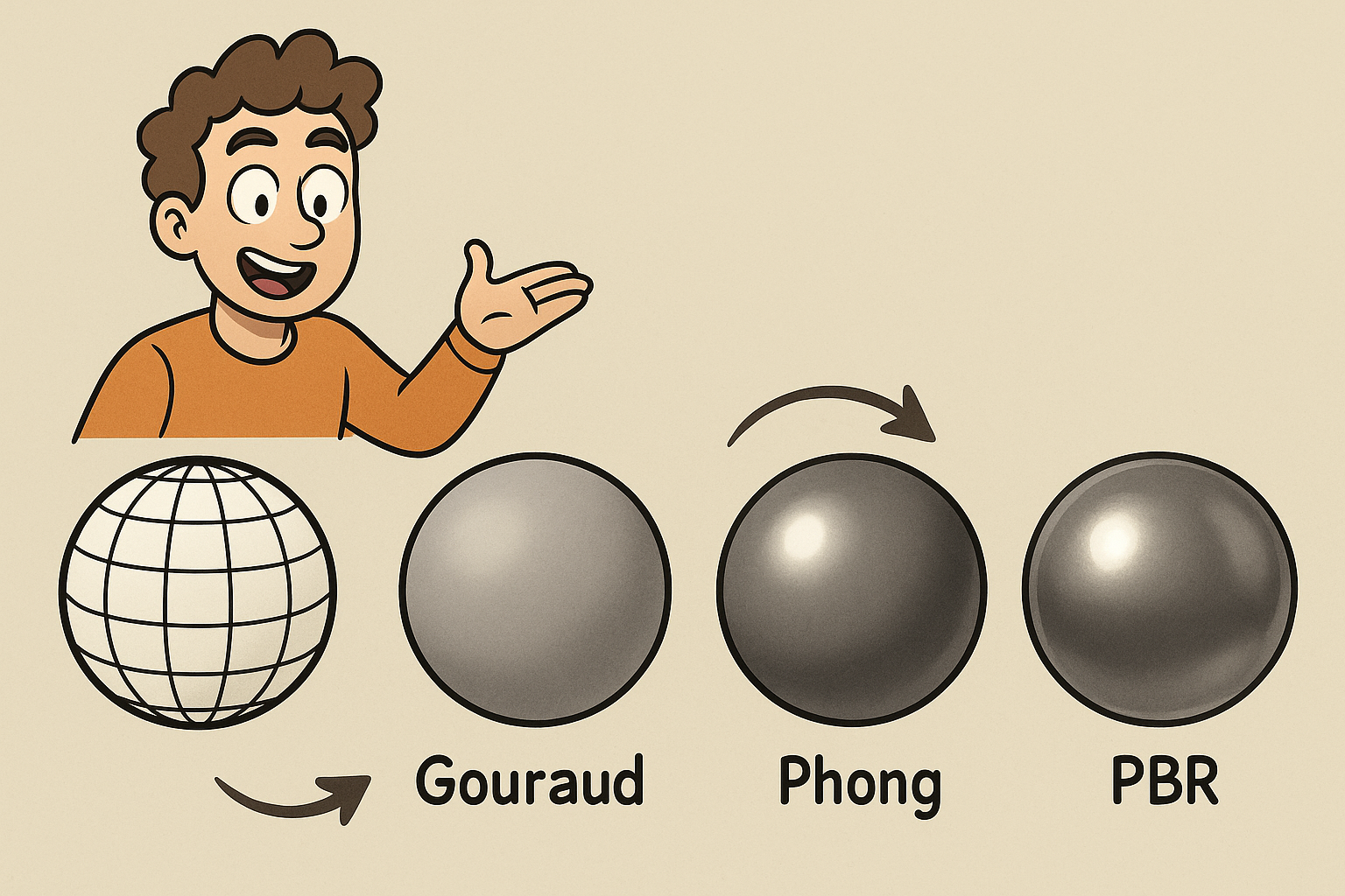
By the early 1970s, CAD workstations were still dominated by wireframe, a representation that was computationally cheap but visually ambiguous. The inflection point began with Henri Gouraud’s 1971 vertex-normal interpolation, a technique that averaged surface normals at vertices and linearly interpolated the resulting lighting across triangles. This simple trick performed lighting once per vertex and produced convincing gradients across facets, causing edges to visually dissolve into a continuous surface. Four years later, Bui Tuong Phong refined the vocabulary of “smooth” by proposing per-pixel specular highlights and normal interpolation (commonly called “Phong shading”), which steered the pipeline toward evaluating the lighting model at each pixel instead of merely interpolating vertex-lit colors. Phong’s formulation improved highlight placement and curvature cues—critical when designers read subtle Class-A surfacing—by keeping the normal field smooth and calculating lobe falloff using a shininess exponent.
Between 1977 and 1978, Jim Blinn added the now-classic halfway-vector for specular, creating what is broadly known as Blinn-Phong. He also introduced bump mapping and environment mapping, two lightweight illusions that made flat geometry look detailed and reflective without incurring geometric cost. Importantly, much of this work came through the University of Utah lineage, where Ivan Sutherland’s program shaped researchers who would later seed the graphics industry. The early ecosystem—Evans & Sutherland on the hardware and simulation side, and later Silicon Graphics (SGI)—turned these academic ideas into interactive tools. The bridge from equations to the designer’s screen crystallized when these shading approaches were embedded in the graphics APIs and workstation GPUs that would become the backbone of industrial design and engineering visualization.
- 1971: Gouraud shading enables continuous tonal gradients from vertex lighting.
- 1975: Phong shading moves to per-pixel lighting and normal interpolation for better highlights.
- 1977–1978: Blinn introduces the halfway-vector specular, plus bump and environment mapping for plausible detail.
Platforms and early adoption: from Evans & Sutherland to OpenGL defaults
On the shop floor of visualization in the 1980s, Evans & Sutherland systems, SGI IRIS workstations, and Sun Microsystems machines brought shaded viewports into engineering offices. SGI’s IRIS GL—and later OpenGL—encoded Gouraud/Phong-era thinking directly into the fixed-function pipeline: glLight, glMaterial, and the specular exponent quietly became the lingua franca for how designers “tuned” metal, plastic, and paint. CAD vendors followed suit. Dassault Systèmes’ CATIA, PTC Pro/ENGINEER (which later became Creo), Unigraphics (which evolved into NX at Siemens), and early Autodesk tools adopted shaded viewports that relied on these conventions. As workstations improved raster performance, engineers finally saw curvature and silhouette without waiting for offline renderings.
These defaults mattered for user experience. Designers could rotate a model and see speculars glide, immediately revealing edge blends, fillets, and transitional patches. Alias|Wavefront’s surfacing culture (later within Autodesk Alias) complemented this “shaded” reading with zebra, reflection lines, and curvature plots, creating a visual toolbox for shape decisions. Even when underlying math was NURBS or analytic surfaces, the raster pipeline—via Gouraud or per-pixel Phong variants—was what the eye saw. Critically, the defaults normalized across platforms: from SGI to PC-era OpenGL implementations, the look was similar enough that teams could discuss surfaces in a common visual language. That ubiquity locked Gouraud/Phong into the DNA of CAD interfaces for nearly two decades.
- IRIS GL/OpenGL baked specular exponent, diffuse color, and ambient terms into standard practice.
- CATIA, Pro/ENGINEER, Unigraphics/NX, and Autodesk products inherited these shading conventions.
- Shaded viewports became the baseline for design review, replacing wireframe ambiguity.
Why smooth shading transformed CAD decision-making
Wireframe hid as much as it revealed. With the arrival of smooth shading, designers could read form at a glance—an enormous leap in instant shape legibility. Highlights traced curvature, and silhouette transitions telegraphed continuity, allowing Class-A surfacing reviews to happen interactively rather than by plotting static reflection lines. Zebras and curvature plots still played a role, but a shaded viewport gave a continuous, holistic percept of form. The impact was felt in consumer electronics, appliances, and especially automotive studios, where the difference between pleasing and awkward highlights could hinge on a tenth of a millimeter in a patch transition.
Because Gouraud/Phong was computationally inexpensive, it unlocked interactivity on the hardware of the day. Alias, CATIA, and Unigraphics users could push and pull control points while watching highlight flow in real time. That turned what had been a two-step process—edit, then render—into a single continuous loop. The psychological effect was profound: creative risk-taking accelerated when feedback became instantaneous. Moreover, consistency across teams improved; when everyone looked at similar shaded views, debates could focus on design intent instead of display quirks. Smooth shading, in short, made industrial design practical on the workstation, enabling a modern studio cadence where shapes are negotiated through moving light rather than static drawings.
- Shaded highlights read continuity and curvature far better than wireframe intersections.
- Class-A reviews blended shaded modes with zebra and curvature diagnostics for confidence.
- Interactive performance collapsed the edit–review loop into a continuous creative process.
Limitations the community felt—and why they pushed for better physics
Even as Gouraud/Phong became the default, practitioners understood its shortcuts. The specular model was non-physical: energy wasn’t conserved, lobes were ad hoc, and highlights often looked like plastic regardless of the intended material. Light rigs were brittle—three-point setups with arbitrary intensities, colors, and falloffs that didn’t travel well between studios, departments, or suppliers. A model that looked “right” in one office could look wrong in another, stalling decisions. Aliasing also haunted the pipeline: highlights shimmered with camera motion, and without gamma-aware composition, midtones crushed or washed out unpredictably.
These issues mattered in manufacturing-centric reviews. Automotive clearcoats failed to sparkle; brushed anisotropy collapsed into radial blobs; semi-gloss plastics looked chalky or oily depending on the display’s gamma. Engineers responded with an arsenal of hacks: tuned shininess exponents, fake reflection maps, and carefully staged light rigs. But the brittleness was systemic. Without Fresnel energy accounting or a microstructure model, there was no way to guarantee that a plastic knob, a metal bezel, and a painted body panel would look stable under different lighting. Teams needed principled reflectance—a way to anchor appearance in measurable parameters rather than art direction—if they were to make reliable CMF decisions across locations and platforms.
- Non-physical highlights and energy gain/loss produced “plastic” looks across materials.
- View-dependent hacks and ad hoc light rigs broke portability of appearance.
- Gamma and aliasing issues eroded trust in shaded previews during critical reviews.
Beyond Blinn-Phong: The Microfacet Turn and Physically Based Reflectance
From Torrance–Sparrow to Kajiya: theory that finally met practice
Long before CAD viewports caught up, the theoretical foundations were in place. In 1967, Torrance–Sparrow articulated a microfacet view of surfaces: real materials are composed of tiny facets, each reflecting light according to Fresnel, with geometry-dependent masking and shadowing. In 1981, Robert L. Cook and Kenneth E. Torrance distilled this into a practical Cook–Torrance BRDF, explicitly combining a microfacet normal distribution, Fresnel reflectance, and a geometric term. This framework restored energy accounting and made shininess a proxy for surface roughness—moving away from arbitrary exponents toward physical parameters. Then, in 1986, James Kajiya unified the field with the rendering equation, which describes light transport as a balance of emitted and reflected radiance integrated over all directions. The equation didn’t immediately make CAD faster, but it gave developers a North Star for building physically correct pipelines.
The 1990s added necessary nuance. Greg Ward introduced an anisotropic BRDF (1992) that better handled brushed metals and fabrics by modeling directional roughness. Michael Oren and Shree K. Nayar (1994) improved the diffuse side with a model for rough surfaces that scatter light beyond Lambertian simplicity. These models—plus evolving approximations for Fresnel (notably Schlick’s 1994 approximation)—provided a set of tools capable of representing real-world materials with a few measurable parameters. The gap between theory and interactive product design narrowed as GPUs and APIs matured. What had been an academic ideal started to look implementable in the real-time and near-real-time contexts that CAD demanded.
- Cook–Torrance grounded specular in microfacets, Fresnel, and masking–shadowing.
- Ward anisotropy and Oren–Nayar rough diffuse expanded coverage to brushed and matte materials.
- Kajiya’s rendering equation provided a unifying goal for physically correct pipelines.
Evangelists and enablers: from Blinn’s ingenuity to Debevec’s IBL
Jim Blinn’s graphics ingenuity had already acclimated practitioners to the idea that better math improved pictures. But the push toward physically based rendering (PBR) took new champions. Robert Cook and Kenneth Torrance continued to advocate microfacet realism within production settings, proving that principled reflectance could be practical. In 1997, Paul Debevec introduced image-based lighting (IBL) and HDR environment capture via light probes and panoramic HDR photography. That breakthrough changed CAD-viz expectations: rather than relying on arbitrary key lights, designers could light models with real-world environments—factory floors, design studios, showrooms—and get plausible reflections and shading in a single step. IBL brought context into the viewport and made appearance discussions less about staging and more about truth.
Parallel to these influences, the research community and industry codified fair comparisons and reproducible implementations. The pbrt project (Matt Pharr, Greg Humphreys, and later Wenzel Jakob) taught a generation of developers how to implement microfacet BRDFs, sampling strategies, and energy conservation. Conferences like SIGGRAPH became conduits where CAD and VFX software teams traded methods and reference images. The upshot for CMF and engineering teams was cultural as much as technical: once you see the stability and realism of microfacet-based shading under HDR environments, it’s hard to go back to ad hoc specular hacks. Within just a few release cycles, expectations shifted from “looks good in this rig” to “looks correct under any rig we throw at it.”
- Debevec’s HDR lighting made the environment a first-class input to CAD appearance.
- The pbrt lineage diffused correct microfacet implementations and testing culture.
- Industry dialogue converged on measurable parameters rather than subjective tuning.
Hardware and software pivot: programmable shading and PBR renderers
The hardware turning point arrived with programmable shaders. DirectX 8 and early Cg/HLSL (circa 2002) and later GLSL (mid-2000s) let developers implement custom BRDFs directly on the GPU. Suddenly, the fixed-function limitations of Gouraud/Phong were optional. CAD and visualization teams could code Cook–Torrance variants with Smith masking, GGX/Trowbridge–Reitz normal distributions, and Schlick Fresnel in the viewport. Meanwhile, a new generation of renderers embraced energy-conserving BRDFs and global illumination: mental ray (Mental Images, later NVIDIA), Iray (NVIDIA), Arnold (Solid Angle, later Autodesk), KeyShot (Luxion, with Henrik and Claus Wann Jensen), V-Ray (Chaos, driven by Vladimir Koylazov and Peter Mitev), and Maxwell Render (Next Limit, Victor Gonzalez). Each emphasized physically based materials and robust sampling, making it feasible to preview manufactured finishes credibly without elaborate lighting setups.
For CAD pipelines, these engines provided two benefits. First, they standardized material vocabulary: F0/IOR, roughness, and metalness replaced arbitrary specular levels and glossiness scales. Second, they collapsed the gap between viewport and final imagery—especially with hybrid raster/trace approaches and later GPU path tracing. Designers could trust that a brushed aluminum dial or multi-layer automotive paint seen in the tool would behave similarly in marketing renders. In practice, this meant fewer surprises at handoff and fewer hours retuning materials. Programmable shading demystified the math, and PBR engines made it fast enough that engineering and CMF could rely on it daily.
- Shader languages enabled Cook–Torrance, GGX, and Schlick Fresnel directly in real time.
- PBR engines normalized material semantics across design, viz, and marketing.
- GPU acceleration brought near-photoreal feedback to the designer’s desk.
What changed for engineers and CMF teams: parameters that travel
Microfacet PBR reoriented appearance around consistent, lighting-robust parameters. Rather than sculpting a highlight with shininess hacks, teams now specify roughness (or gloss), base color or albedo, F0/IOR, and optional metalness. These terms are measurable and portable. A brushed aluminum fascia can be dialed via anisotropic roughness, and an ABS plastic knob can be defined by a dielectric F0 near 0.04 and a roughness that matches the mold finish. Automotive finishes benefit from layered BRDFs: a pigmented base, flake/flake normal perturbation, and a clearcoat layer with its own Fresnel and micro-roughness. Because the math respects energy conservation and Fresnel behavior, materials stay plausible across environments without re-lighting.
For CMF practitioners, this stability translates into reduced ambiguity between departments. A supplier can deliver a measured BSDF or a well-parameterized material, and it will look correct in an OEM’s HDR-lit design review. Anisotropy for brushed textures, sheen for fabrics, and clearcoat for coatings are no longer special effects; they are first-class parameters. The effect on workflow is profound: once materials are defined in this space, they can travel from early CAD review to DCC renders and even to AR/VR viewers with minimal translation. In a world of globalized supply chains and distributed teams, that portability is a quality-of-life improvement—and a risk reducer—of the first order.
- Roughness, F0/IOR, and metalness anchor materials in measurable, portable terms.
- Layered BRDFs accurately capture clearcoat, flakes, and anisotropy for manufactured finishes.
- Lighting-robust definitions reduce relighting and retuning across the product pipeline.
PBR Lands in CAD Workflows: Standards, Vendors, and Real-Time Viewports
Standards and interchange: from Disney “Principled” to glTF, USD, MaterialX, MDL, and AxF
The final barrier to mainstream PBR inside CAD was standardization. In the 2010s, Brent Burley’s Disney “Principled” BSDF synthesized industry experience into a compact, art-directable but physically grounded model. That template informed the popular metallic–roughness and specular–glossiness workflows and allowed different engines to converge on similar controls. In 2017, glTF 2.0 standardized a lightweight PBR core for web and AR, making it easy to hand off assemblies and parts with appearance intact. For higher fidelity pipelines, MaterialX (originating at Industrial Light & Magic and now under the ASWF) and USD/USDShade (open-sourced by Pixar) established portable representations of shading graphs, parameters, and texture bindings. On the manufacturer side, NVIDIA MDL provided a portable material definition language that compiles into multiple renderers, and X-Rite’s AxF encapsulated measured appearance—including anisotropy, sparkle, and clearcoats—in a vendor-neutral format.
Equally important were practices that surrounded these standards. Image-based lighting (IBL) with HDRIs became the default, supplanting the old three-point rigs. Linear color workflows and tone mapping (often ACES-inspired) addressed legacy gamma problems, ensuring that midtones and highlights compress predictably across displays. As these norms settled, CAD vendors could adopt common terms without forcing users into proprietary corners. The combination of principled material models, portable encodings, and HDR lighting made it possible for a part to look consistent in a CAD viewport, a marketing render, and a browser-based configurator—without a change of parameters. That continuity is exactly what engineering and CMF teams had been asking for since the days of brittle Blinn-Phong rigs.
- Disney “Principled” BSDF normalized user-facing parameters across engines.
- glTF 2.0 carried lightweight PBR to web/AR, while USD/MaterialX enabled high-fidelity graphs.
- MDL and AxF brought portable, often measured, appearance to enterprise pipelines.
- HDRIs, linear workflows, and tone mapping stabilized the visual baseline across devices.
Where CAD vendors landed: viewport PBR and integrated ray tracing
With standards maturing, vendors moved quickly. Dassault Systèmes integrated Iray into CATIA Live Rendering and across 3DEXPERIENCE apps, pairing PBR materials with GPU-accelerated photoreal feedback. SolidWorks Visualize (born from Bunkspeed and powered by Iray) gave mechanical designers a direct line from CAD to marketing-grade imagery without arcane setup. Siemens NX evolved toward NX Render and Ray Traced Studio, embracing GPU path tracing on RTX-class hardware and a robust PBR viewport so that in-canvas reviews match final output closely. PTC Creo deepened its KeyShot-based Render Studio, letting teams carry the same PBR definitions from design review through to presentation.
Autodesk pushed PBR across its product families: Fusion 360 ships with real-time PBR and cloud/local ray tracing; Arnold spans DCC tools and supports principled shading; Inventor and Alias workflows settled on HDRI-driven previews with principled materials, aligning what modelers see with what renderers produce. In the cloud, Onshape and other browser CAD systems leveraged WebGL and early WebGPU to provide collaborative PBR viewports and frictionless glTF export. Taken together, these moves brought consistent, believable materials into the core modeling environment rather than relegating them to a downstream rendering silo. And because HDRIs and tone mapping are part of the default setup, the old calibration fights have been replaced by predictable, portable looks.
- CATIA, NX, Creo, Fusion 360, Inventor, Alias, and Onshape established PBR as a first-class viewport feature.
- GPU path tracing with RTX bridged the gap between interactive and photoreal review.
- Browser-based PBR and glTF export democratized appearance across stakeholders.
Measured reality and CMF: scanners, SVBRDF, and shared libraries
To close the loop between spec sheets and visuals, teams increasingly rely on measurement. X-Rite provides multi-angle spectrophotometers (e.g., MA-T series) for effect paints and the AxF format for distributing measured appearance. Vizoo offers xTex scanners that capture SVBRDF maps for leathers, plastics, and textiles, preserving anisotropy and microstructure variations that matter in handfeel-driven products. Material definitions travel via MDL, MaterialX, and USDShade graphs, ensuring that properties like clearcoat thickness, flake sparkle, or woven anisotropy survive toolchain boundaries. On the content creation side, Substance 3D (originally Allegorithmic, acquired by Adobe) entered industrial design departments with libraries and authoring tools tuned for manufacturing-relevant textures, enabling CMF teams to prototype finishes that match both metrology and marketing needs.
These pipelines aren’t just about pretty pictures. When a textile’s warp–weft anisotropy or a polycarbonate’s molded micro-roughness is encoded, designers can evaluate risk early: Will a seam telegraph under showroom lighting? Will a brushed panel’s directionality clash across assembled parts? By anchoring appearance in measured or procedurally parameterized data, organizations build shared libraries that reduce duplicated effort and prevent regressions when assets move from CAD to DCC to real-time engines. The payoff is predictability: a paint chip scanned once can set expectations for the studio, the supplier, and the studio-lighted reveal—no relighting sessions required.
- X-Rite AxF and Vizoo SVBRDF capture preserve anisotropy, clearcoat, and flake structure.
- MDL, MaterialX, and USDShade carry appearance through heterogeneous tools.
- Substance 3D bridges CAD and marketing via shareable, parameterized PBR materials.
Persistent challenges: units, spectra, calibration, and scale
Even with PBR’s gains, several challenges remain. First is the interface between engineering data and appearance parameters. CAD operates in millimeters and microns, but roughness lives in an abstract [0–1] space unless tied to measured microgeometry. Without unit-aware pipelines, scale changes can inadvertently alter gloss perception. Second, most production systems still run in RGB; differences between dyes, pigments, and interference effects are better explained spectrally, which matters for automotive reds, pearlescents, or complex textiles. Third, display calibration remains uneven. While tone mapping and HDR workflows (PQ/HLG) are improving fidelity, review rooms and laptops rarely match, leading to color and contrast surprises in sign-off.
Interchange fidelity is another friction point. Mapping between MDL, MaterialX, USD, and glTF can still drop features—clearcoat normal maps, multi-lobe sheen, or measured BRDF lobes—if exporters target the lowest common denominator. Normal map conventions and tangent spaces vary, causing shading seams across tools. At the performance end, large assemblies force tradeoffs between real-time speed and full-accuracy shading; even with RTX-class GPU ray tracing, teams often rely on hybrid pipelines. Addressing these gaps means investing in unit-aware roughness/normal conventions, expanding spectral support where it matters, instituting per-site display calibration, and tightening schema mappings so that layered materials survive round-trips intact. The industry has the pieces; the remaining work is orchestration and discipline.
- Unit-aware roughness and normal conventions are needed to stabilize gloss across scales.
- Spectral pipelines will better handle pigments, pearlescents, and interference effects.
- Consistent calibration and HDR adoption reduce cross-site review discrepancies.
- Robust mappings across MDL, MaterialX, USD, and glTF preserve layered, measured detail.
Conclusion: From Comprehension to Decision-Making—and What Comes Next
How shading models reshaped CAD reviews
The journey from Gouraud and Phong to microfacet PBR transformed CAD from a tool of geometrical comprehension into a platform for confident decision-making. Gouraud and Phong unlocked the first great leap—interactive smoothness—turning wireframe puzzles into readable forms with flowing highlights. That made Class-A surfacing and ergonomic evaluations practical in real time. The microfacet turn completed the picture: by respecting Fresnel and energy conservation and by grounding gloss in roughness rather than arbitrary shininess, PBR delivered believable, portable appearance under any lighting. Where teams once argued about light rigs, they now reason about measurable parameters. Where material definitions used to collapse when moved between studios, they now persist via principled encodings and HDR context. The upshot is less waste: fewer retunes, fewer miscommunications, fewer review loops spent fixing visuals rather than talking about design intent.
- Gouraud/Phong made interactive curvature reading possible and universal in CAD UIs.
- Microfacet PBR made materials consistent across environments, tools, and teams.
- Design reviews shifted from display staging to product-relevant judgments.
The workflow winners: IBL, principled parameters, and shared libraries
What ultimately won was not a single model, but a workflow. Consistent IBL created a stable reference for reviews. Principled parameter sets—roughness, F0/IOR, metalness, layered lobes—gave teams a shared vocabulary that survives tool changes. Shared libraries in MaterialX, MDL, USDShade, and glTF provided the glue so that a part looks the same in a CAD viewport, a GPU path-traced render, and a web configurator. GPU ray tracing on RTX-class hardware then anchored this fidelity inside the modeling canvas, making “what you see while editing” close to “what stakeholders will approve.” Combined, these shifts reduced the cognitive tax of visual validation; designers can move from concept to confidence faster because the viewport is no longer a separate world with its own rules.
- IBL standardizes context; principled parameters standardize material behavior.
- Portable encodings (glTF, USD, MaterialX, MDL, AxF) reduce translation loss.
- GPU path tracing brings review-ready fidelity directly into CAD.
What’s next: measured and spectral materials, OpenPBR/MaterialX convergence, and tighter manufacturing links
The next frontier is convergence and measurement depth. Expect broader adoption of measured/spectral materials where they matter—automotive paints, cosmetics packaging, advanced textiles—and standardized ways to move those spectra through pipelines. Efforts like OpenPBR within the MaterialX ecosystem aim to harmonize principled models across engines so that “principled” truly means interchangeable, not just similarly named. As HDR displays proliferate in studios and showrooms, review loops will increasingly place HDR in the loop by default, further reducing discrepancies between on-screen and in-situ impressions.
The most consequential advance may be the link between manufacturing metadata and appearance. If CAD already houses surface finish callouts (Ra/Rz), coating stacks, and texture specifications, those parameters should drive the material model—ideally via measured correlations—so that what engineers specify is exactly what stakeholders see. Tighter links between PLM systems and appearance libraries will allow suppliers to deliver AxF or MDL assets alongside spec sheets, and for CAD to validate them under standardized HDR contexts automatically. In the long arc from Gouraud to PBR, the pattern is clear: every time the industry replaced heuristics with principled, portable definitions, design cycles got shorter and decisions got better. The next chapter simply extends that logic, bringing measurement, spectra, and manufacturing semantics into the heart of visual decision-making—so that the virtual product and the physical one are two truthful views of the same thing.
- MaterialX/OpenPBR aims to align principled shading across engines for true portability.
- Spectral support and measured datasets will raise fidelity for effect finishes and fabrics.
- PLM-to-appearance links will bind finish callouts and coatings to renderable, reviewable materials.
Also in Design News