Your Cart is Empty


Design Software History: From Drafting Boards to Intelligent Plant CAD Systems
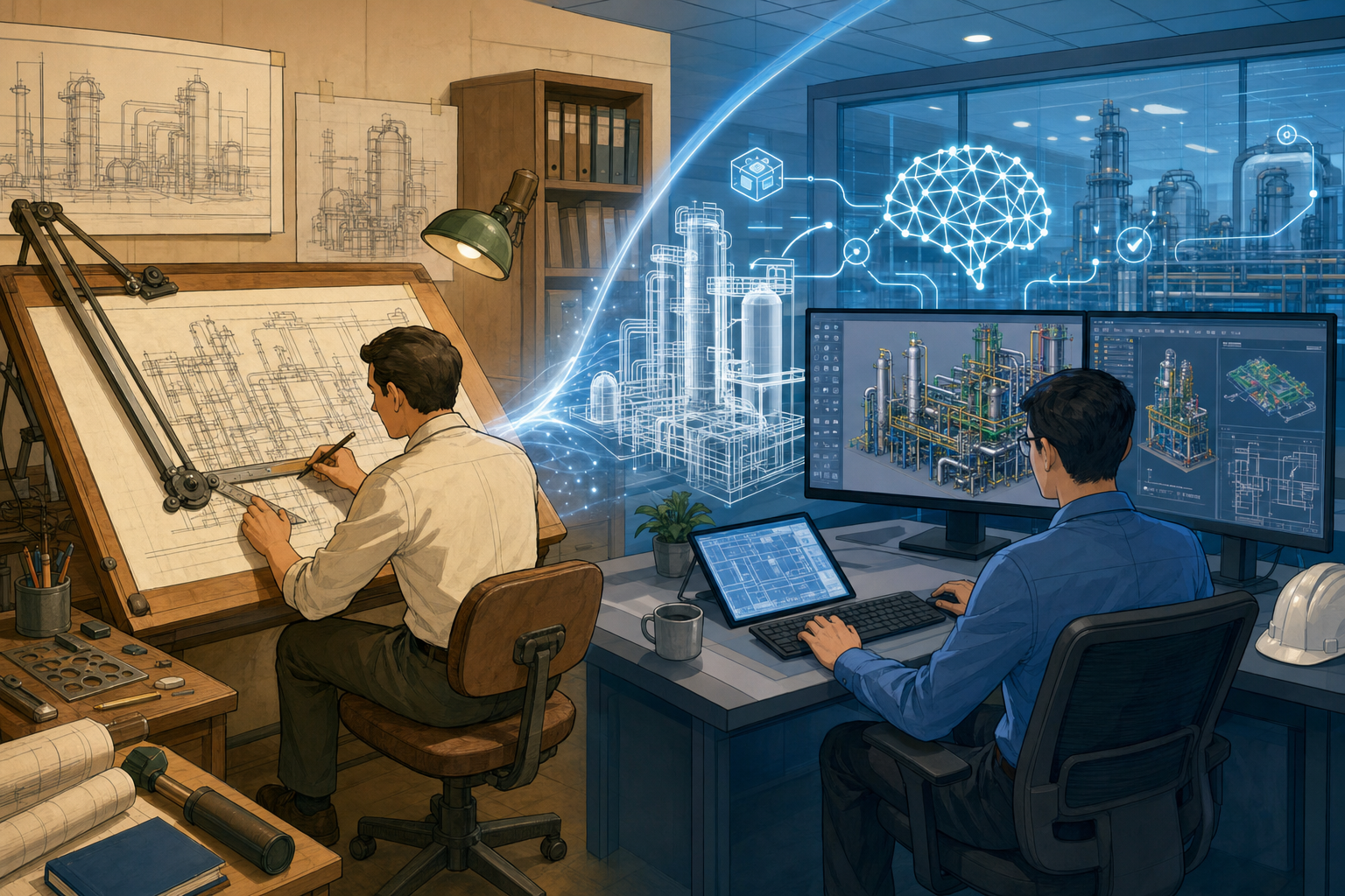


From Drafting Boards to Early Plant CAD
The Industrial Drawing Burden
Process facilities forced design software into a different historical path because a refinery, chemical plant, power station, offshore platform, or pharmaceutical facility is not a single object in the way a gearbox, aircraft bracket, or consumer product can be treated as a discrete artifact. It is a vast interconnected system of pipes, vessels, pumps, compressors, valves, supports, instruments, cable trays, steel structures, access platforms, insulation zones, drainage paths, safety systems, and maintenance spaces. Before computers became central to plant design, this complexity was managed through immense drawing sets: plot plans, equipment layouts, piping plans, sections, elevations, piping and instrumentation diagrams, instrument hook-ups, structural drawings, electrical layouts, and thousands of piping isometrics. The industrial problem was not merely drawing speed; it was coordination. A small revision to a vessel nozzle could affect connected pipe routes, pipe supports, access clearances, valve orientations, stress calculations, fabrication spools, material takeoffs, and construction sequencing. Traditional 2D drafting could describe the plant, but it struggled to keep the plant coherent as a changing spatial and engineering system.
Digital Drafting Before Intelligence
Early CAD entered plant engineering as a drafting accelerator rather than as an intelligent process modeling environment. The first systems reproduced familiar manual deliverables in digital form: piping plans, sections, elevations, isometrics, schematic P&IDs, equipment outlines, and title-block-controlled construction drawings. The value was immediate but limited: cleaner linework, reusable symbols, easier revisions, more consistent lettering, faster plotting, and reduced dependence on repetitive manual board work. A drafter could copy a pump symbol, adjust a piping run, revise a valve tag, or regenerate a plotted drawing with far less physical effort than erasing ink or redrawing mylar sheets. This phase mattered historically because it established CAD as acceptable infrastructure inside engineering, procurement, and construction firms. However, the computer still largely behaved as an electronic drafting board. A pipe represented by lines did not truly know its nominal diameter, pressure class, material specification, insulation thickness, service, or fabrication implications. Plant CAD began as digital documentation for an industry drowning in drawings, not as a fully intelligent industrial data system.
Companies That Shaped the Early Graphics Era
Several companies helped define this workstation and mainframe-era transition. Intergraph, founded in 1969 by Jim Meadlock and colleagues after work connected to NASA and engineering graphics, became especially influential in plant and process design because its hardware and software were adopted by large engineering organizations that needed serious graphics, database links, and project-scale drawing control. Computervision, founded by Marty Allen and Philippe Villers, also played a major role in establishing computer-aided engineering graphics for manufacturing and industrial design before the personal-computer CAD era matured. Prime Computer supplied minicomputer platforms that supported engineering applications in large organizations, while other vendors in the same period supplied expensive but powerful terminals, plotters, digitizers, and graphics workstations. Later, Bentley Systems, founded by Keith Bentley and Barry Bentley, became central through MicroStation-based workflows that found deep adoption in infrastructure and plant environments. Autodesk, founded in 1982 by John Walker and colleagues, made AutoCAD a widespread 2D platform, allowing plant drafting departments to standardize on lower-cost desktop CAD and later adopt vertical plant applications built around AutoCAD conventions.
- Early CAD improved drawing cleanliness, repeatability, revision speed, and plotted output quality.
- Large plant projects still depended on human interpretation to coordinate spatial relationships and engineering meaning.
- The earliest digital plant drawings were valuable, but most geometry remained semantically weak.
- The next software leap required pipes, valves, instruments, and equipment to become data-bearing engineering objects.
The Rise of Intelligent Piping Models
When a Pipe Became an Engineering Object
The decisive change in plant design software occurred when a pipe stopped being an arrangement of graphical strokes and became a structured engineering object. In manual drafting or simple 2D CAD, a pipe might be shown as two parallel lines, a centerline, a symbol, or an isometric segment. In intelligent plant systems, that same pipe acquired identity and behavior. It carried attributes such as nominal diameter, schedule, material, pressure class, insulation, heat tracing, line number, service, specification break, flow direction, connection rules, and relationships to valves, flanges, elbows, tees, reducers, gaskets, bolts, supports, drains, vents, and instruments. This shift seems technical, but it was historically profound. Once the pipe became an object, software could check whether a stainless steel line was being connected to the correct class of flange, whether a reducer followed allowed catalog rules, whether a valve matched the proper rating, and whether a line list agreed with the 3D model. The plant model became a carrier of engineering intent, not merely a more attractive drawing.
Why Piping Pushed CAD Beyond Geometry
Piping design pushed CAD beyond ordinary geometric modeling because process facilities are governed by rules, catalogs, specifications, safety constraints, and construction practices. A mechanical CAD system can model a precise solid part, but a plant system must model connectivity across thousands of components acquired from manufacturers and constrained by project standards. Software had to understand pipe specifications, allowable fittings, routing constraints, slope and drainage, minimum clearances, maintenance access, stress concerns, support spacing, hydrotest boundaries, spool fabrication limits, welding requirements, and material procurement codes. Designers were not merely creating shapes in space; they were selecting from controlled catalogs and enforcing project rules. An elbow was not simply a curved solid. It represented a manufacturer type, nominal bore, radius, wall thickness, material grade, end preparation, pressure rating, commodity code, and purchasing description. This is why plant CAD systems developed differently from mainstream drafting and mechanical modeling tools. Geometry alone was insufficient; process design needed geometry connected to engineering standards, procurement logic, and fabrication information.
- Typical intelligent pipe attributes include nominal diameter, line number, service, pressure class, material, insulation, and specification.
- Typical piping components include valves, flanges, elbows, tees, reducers, gaskets, bolts, vents, drains, and supports.
- Typical rule checks involve catalog validity, connection compatibility, slope, clearance, access, and specification compliance.
The Database as the Hidden Model
The rise of intelligent piping made databases as important as graphics. A plant model could no longer be managed as a loose collection of drawing files because the real object of value was the relationship between equipment tags, line numbers, component catalogs, material quantities, drawings, revisions, and construction deliverables. Process plant software therefore evolved into a hybrid of CAD geometry and engineering data management. The model became a source for bills of materials, valve lists, line lists, isometric drawings, fabrication reports, procurement records, weld counts, bolt summaries, and construction packages. This database-centered architecture also changed project organization. Piping designers, process engineers, stress analysts, material engineers, procurement teams, and construction planners could use different views of the same underlying information. The drawing remained important, but it increasingly became an output rather than the only master record. This was one of the most important transformations in CAD history: in plant design, the authoritative model was not just a geometric scene; it was a controlled industrial database whose geometry, attributes, catalogs, and documents had to remain synchronized.
Landmark Platforms and Vendor Histories
Intergraph PDS, or Plant Design System, became a landmark in intelligent 3D plant design because it combined 3D plant modeling, piping specifications, component placement, drawing extraction, and project database concepts at the scale required by major EPC firms. Intergraph later developed broader SmartPlant technologies, and after Hexagon acquired Intergraph in 2010, Hexagon became one of the strongest global forces in plant design, engineering information management, and digital asset technology. AVEVA PDMS emerged from the British CADCentre tradition around Cambridge, a historically significant environment linked to early computer-aided design research and industrial software development. PDMS became a dominant global plant design platform because it was built around data-rich 3D modeling for complex facilities. Bentley AutoPLANT and later OpenPlant advanced database-driven plant workflows in the MicroStation and broader Bentley environment. Autodesk Plant 3D brought intelligent piping behavior to a wider AutoCAD-based user base, especially among organizations that wanted familiar drafting interaction combined with catalogs, specs, P&ID links, and 3D piping. These platforms show that process design software grew into its own technical ecosystem, shaped by plant engineering needs rather than generic CAD ideals.
From 3D Plant Models to Integrated Process Design Platforms
Coordination Across Disciplines
As 3D plant modeling matured, the historical problem shifted from making one discipline more productive to coordinating many disciplines inside a shared industrial facility. Piping had to coexist with process engineering, equipment layout, structural steel, HVAC, electrical systems, instrumentation, civil works, safety systems, access planning, modularization, and construction scheduling. This coordination requirement was far more demanding than placing objects in a visual scene. A compressor needed foundations, clearance zones, pipe connections, electrical feeds, instrumentation, maintenance access, lifting space, and safety separation. A pipe rack carried process lines, utility lines, cable trays, supports, and sometimes walkways, all of which had to obey both geometric and engineering constraints. A valve placed at the wrong elevation could be technically connected but operationally inaccessible. A line routed through a steel member might be detected as a clash, but a line routed too close to a hot surface or without withdrawal space for maintenance represented another kind of design failure. Integrated plant platforms evolved because the facility itself was the product, and no single drawing discipline could fully define it.
Clash Detection and Digital Review
Clash detection became one of the strongest justifications for 3D plant design because it addressed a painful and expensive industrial reality: errors discovered in the field cost far more than errors discovered in the model. In a 2D workflow, plan drawings and sections depended on designers mentally reconstructing three-dimensional relationships. Even highly skilled designers could miss an interference between a pipe, a platform brace, an instrument stand, and a cable tray if each item was documented separately. With 3D plant models, large facilities could be reviewed digitally before fabrication and construction. Review meetings changed from comparing stacks of drawings to navigating coordinated models, checking access envelopes, verifying elevations, examining congested pipe racks, and inspecting equipment areas from multiple viewpoints. EPC firms used model reviews to coordinate distributed teams, reduce field rework, and produce more reliable construction documentation. The economic argument was powerful: a clash avoided before steel fabrication or spool shipment could prevent schedule delays, site modifications, safety risks, and contractual disputes. In plant design history, 3D modeling became valuable less because it looked realistic and more because it made coordination failures visible.
- Digital model reviews exposed hard clashes between pipes, steel, equipment, HVAC, cable trays, and civil works.
- Soft clashes revealed inadequate maintenance access, valve reach problems, removal envelopes, and safety clearances.
- Distributed project teams could review common models instead of relying only on 2D drawing interpretation.
- Construction planning benefited when model geometry was linked to work packages, modules, and fabrication sequences.
The Central Role of P&IDs
Piping and Instrumentation Diagrams became central to integrated plant platforms because they express process intent rather than physical layout. A P&ID shows equipment, process lines, instruments, control loops, valves, drains, vents, and connectivity in schematic form. It is not geographically accurate, but it is legally, operationally, and technically important. Connecting intelligent P&IDs to 3D models became one of the hardest and most valuable software challenges in plant design. The system had to reconcile a schematic process line with its physical routed counterpart, making sure that line numbers, equipment tags, instrument loops, valve tags, and connection relationships remained consistent. Intelligent P&IDs allowed users to validate whether a valve shown in the diagram appeared in the 3D model, whether an instrument connection existed where required, whether a pump suction and discharge line had correct tags, and whether process connectivity matched the physical design. This linkage changed the meaning of plant documentation. The P&ID was no longer only a drawing to be checked manually against layout drawings; it became part of a broader data network connecting process design, physical design, procurement, commissioning, and operations.
Scanning, Twins, Simulation, and Standards
Adjacent technologies expanded plant platforms beyond initial design into retrofit, operation, inspection, and lifecycle asset management. Laser scanning and point clouds became especially important for brownfield plant projects, where existing facilities often differed from old drawings because of decades of modifications. Companies such as Leica Geosystems, FARO, Trimble, and later software providers in the Hexagon, Bentley, Autodesk, and AVEVA ecosystems helped normalize the use of reality capture for plant work. Point clouds allowed designers to route new piping through existing congested environments with greater confidence and to compare planned modifications against actual site conditions. Digital twins extended the idea further by linking 3D models, engineering data, inspection records, sensor data, maintenance history, and operational context. Simulation tools for flow, pipe stress, process performance, safety analysis, and transient behavior became increasingly connected to design data, even if perfect integration remained difficult. Standards such as ISO 15926 attempted to structure lifecycle plant data so that information could survive handovers between software systems, contractors, owners, and operating teams. The pattern is clear: plant design software became less like conventional mechanical CAD and more like an industrial information system wrapped around a 3D model.
Why Piping and Process Design Became Its Own Software World
A Historical Arc from Drafting to Information Systems
The history of piping and process design software follows a clear arc. It began with computer-aided drafting, when the main goal was to reduce the burden of manual drawing production in industries that generated enormous documentation sets. It then moved into intelligent piping objects, where a pipe, valve, flange, or vessel nozzle carried attributes and rules rather than appearing only as lines and symbols. It expanded into database-driven 3D plant models, where geometry, catalogs, project specifications, material takeoffs, isometric extraction, and drawing deliverables were connected. It is now evolving toward digital twins, cloud collaboration, lifecycle asset information, reality capture, and analytics-supported operations. This progression reflects a deeper truth about design software history: industries do not simply adopt generic CAD tools and use them unchanged. They bend software around their own knowledge systems, commercial pressures, regulatory duties, construction methods, and risk profiles. In process plant design, the model became not just a representation of geometry but a living database of industrial intent, containing decisions that matter from early layout through decades of operation.
What Made Plant Design Different from Ordinary CAD
Piping and process design became specialized because the field combined scale, connectivity, revision control, engineering rules, construction sequencing, safety requirements, and long-term maintenance obligations in unusually demanding ways. A building has systems, and a machine has assemblies, but a process plant has thousands of connected components whose purpose is to move, transform, heat, cool, compress, react, separate, measure, and control fluids under pressure and often under hazardous conditions. Catalog-driven design was essential because components needed to match project specifications and industry codes. Revision control was essential because a change to one line could affect process safety, stress analysis, pipe supports, insulation quantities, procurement, and commissioning. Construction sequencing mattered because a plant is fabricated and assembled through modules, spools, steel packages, field welds, lifts, and access constraints. Operations and maintenance data mattered because the facility would run for decades, and future engineers needed to understand what had been built, modified, inspected, isolated, repaired, or replaced. No ordinary drawing-centered CAD workflow could carry that burden alone, which is why plant software developed its own vocabulary, architecture, and ecosystem.
- Scale: major facilities contain thousands or millions of modeled items and related records.
- Connectivity: process lines, instruments, equipment, and controls must remain logically consistent.
- Catalog-driven design: components are selected from approved specifications rather than invented freely.
- Safety and regulation: pressure, temperature, hazardous service, and operational risk affect design decisions.
- Lifecycle value: plant information remains useful long after initial construction is complete.
The Larger Lesson in Design Software History
The larger lesson is that the most consequential design software often emerges when geometry is forced to merge with domain knowledge. Piping software did not become important because it drew cylinders and elbows better than other CAD tools. It became important because it encoded the way process industries think: in line numbers, service classes, specifications, equipment tags, instrument loops, pressure boundaries, material classes, procurement packages, fabrication spools, and operational assets. The history of Intergraph PDS, AVEVA PDMS, Bentley AutoPLANT and OpenPlant, Autodesk Plant 3D, and Hexagon’s wider plant technology portfolio demonstrates that plant design tools succeeded when they respected the industrial information structure behind the drawings. Modern platforms owe as much to database architecture, engineering standards, catalog management, and construction logistics as they do to geometric modeling. That is why piping and process design became one of the most specialized and consequential branches of the CAD family tree. In this branch, the “model” is not merely what something looks like; it is what the plant is, how it is connected, how it will be built, and how it must be understood over its operating life.
Also in Design News