
Your Cart is Empty


Design Software History: Object-Oriented Architecture in CAD: From Procedural Drafting Code to Parametric Modeling Platforms
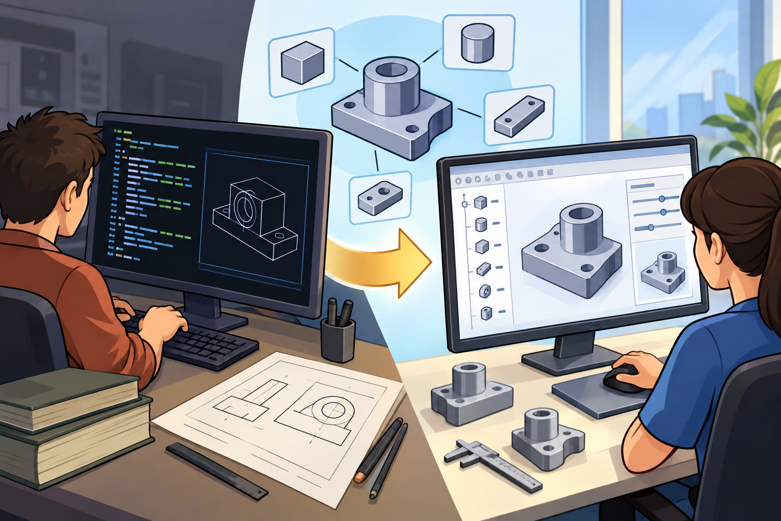


From Procedural CAD Code to Object-Oriented Thinking
The architectural strain behind early CAD growth
Early CAD systems were built in an environment where graphics hardware was expensive, memory was scarce, processors were slow, and software engineers often worked close to the machine. Systems such as Ivan Sutherland’s Sketchpad at MIT, General Motors’ DAC-1 work with IBM, early Computervision products, Applicon systems, and McDonnell Douglas CAD/CAM tools proved that interactive computer-aided design could change engineering practice. Yet the internal architecture of many early systems reflected the practical constraints of the time: large monolithic codebases, procedural geometry routines, device-specific drawing logic, and tightly coupled application functions. A command to draw a line, trim an arc, update a drafting view, or display a hidden-line image might depend on separate procedural routines that knew too much about the data layout, the display terminal, and the calling sequence of other routines. As features expanded from 2D drafting to wireframe modeling, then surface modeling, and eventually solid modeling, maintenance became increasingly difficult because every new capability could disturb older code paths that were never designed for modular evolution.
Why operation-centered software became limiting
Many early CAD programs separated software by operation rather than by the design entities engineers manipulated. The code for creating a line, editing a line, displaying a line, snapping to a line, dimensioning a line, and exporting a line could live in different procedural modules, each with its own assumptions. Arcs, splines, surfaces, solids, dimensions, constraints, drawing views, blocks, symbols, and annotations were frequently handled through specialized routines rather than through a unified representation of design objects. This worked when systems were relatively narrow, but it became brittle as CAD expanded into associative drawings, parametric modeling, assemblies, numerical control, manufacturing planning, and simulation. If a new display mode, selection rule, regeneration algorithm, or file format was introduced, many modules had to be modified. The design intent of the engineer was not reflected in the structure of the software. Instead of a “curve” knowing how to evaluate itself, transform itself, or serialize itself, the system relied on external procedures that operated on passive data structures. That separation created duplicated logic, inconsistent behavior, and high engineering cost.
The broader computing ideas that changed the conversation
Object-oriented programming offered a different mental model. Instead of treating data as inert records manipulated by distant procedures, an object combined data with behavior. A geometric entity could own its coordinates, topology references, display methods, transformation behavior, and persistence rules. The intellectual lineage mattered. Simula, developed in the 1960s by Ole-Johan Dahl and Kristen Nygaard at the Norwegian Computing Center, introduced classes, objects, and inheritance in the context of simulation. Smalltalk, developed at Xerox PARC by Alan Kay, Dan Ingalls, Adele Goldberg, and their colleagues, pushed the idea of objects communicating through messages and helped establish a more expressive style of interactive software. C++, created and popularized by Bjarne Stroustrup at Bell Labs, brought object-oriented techniques into the performance-sensitive world of systems programming, where commercial CAD developers could not afford to ignore speed, memory control, and compatibility with existing C code. The central question became unavoidable: could object-oriented design help CAD systems become more modular, extensible, and suitable for increasingly complex product modeling?
CAD Entities Become Software Objects
Why CAD concepts mapped naturally to objects
CAD was one of the software domains where object-oriented ideas felt unusually natural because engineering models already contain distinguishable entities with identity, state, and behavior. A line has endpoints and knows how it should be displayed, selected, offset, transformed, intersected, or dimensioned. A surface has parameterization, trimming boundaries, normal evaluation, curvature behavior, and display tessellation. A solid body has topology, faces, edges, vertices, mass properties, Boolean behavior, and manufacturing meaning. A sketch constraint has references, mathematical conditions, degrees of freedom, and solver participation. An assembly component has placement, dependencies, configurations, suppression state, and links to part definitions. Feature-based CAD made the mapping even clearer: an extrude, revolve, fillet, chamfer, shell, draft, loft, sweep, or pattern is not merely a command result; it is a persistent object in the model history. This alignment between engineering semantics and software architecture explains why CAD entities as software objects became such a powerful design principle in commercial systems.
Behavior moves closer to the data it affects
When geometry objects contain their own methods for display, transformation, selection, regeneration, and serialization, software becomes easier to reason about. A curve object can provide a common interface for evaluating a point at a parameter, calculating a bounding box, testing selection proximity, or writing itself to a file. A surface object can provide normal evaluation, tessellation hints, trimming-loop access, and intersection participation. A feature object can know which sketch, reference plane, parameters, and parent features it depends on. This architecture reduces the need for scattered procedural code that repeatedly asks what kind of entity it is dealing with. Instead, the system can ask the object to perform the appropriate operation. In commercial CAD development, this was not only a matter of elegance; it affected reliability. A single shared method for transformation or persistence reduced inconsistencies between drafting, modeling, visualization, and data exchange. As modeling systems grew from thousands to millions of lines of code, this locality of responsibility became indispensable.
Inheritance organizes families of geometry and features
Inheritance gave CAD developers a way to express shared behavior without erasing important differences. A general curve class could define essential capabilities such as parameter evaluation, endpoint access, trimming behavior, bounding-box calculation, and transformation. Subclasses could then represent a line, arc, ellipse, spline, or NURBS curve, each with specialized mathematical logic. A line can be evaluated with a simple linear expression; a NURBS curve may require basis functions, knot vectors, control points, weights, and careful numerical handling. The same pattern appeared in feature-based modeling. A general feature class might define naming, suppression state, parent-child dependencies, regeneration status, user parameters, and error reporting. Subclasses such as extrude, revolve, fillet, chamfer, draft, shell, hole, rib, loft, sweep, and pattern could then implement their own creation and regeneration behavior. This did not eliminate complexity, but it gave developers a structure for placing complexity where it belonged. In systems influenced by parametric modeling, this hierarchy helped connect user-visible modeling operations with deeper geometric and topological machinery.
- A general curve object could define shared behavior for lines, arcs, splines, and NURBS entities.
- A general feature object could define regeneration, dependency tracking, naming, and suppression behavior.
- Specialized subclasses could preserve the mathematical and engineering differences between entity types.
- Common interfaces allowed commands to interact with many entity types without duplicating logic.
Polymorphism improves user interaction and system consistency
Polymorphism was especially valuable in user interaction because CAD users expect a single command to work across many entity types. A selection command should recognize a model edge, sketch curve, drawing annotation, datum plane, assembly component, or surface trim boundary without requiring the user to enter a different software universe for each entity. A move, rotate, copy, hide, suppress, measure, delete, or inspect operation should behave consistently while still respecting the entity’s special rules. In a procedural system, this often leads to long conditional statements that ask whether the object is a line, arc, face, body, dimension, symbol, feature, or component. In an object-oriented design, the command can call a shared interface and allow the selected entity to provide its own response. This is not merely a programming convenience; it shapes the user experience. Consistent selection highlighting, grips, manipulators, property panels, context menus, and undo behavior became easier to implement when entities followed coherent object protocols across drafting, modeling, assembly, and drawing environments.
Parametric CAD and the Need for Structured Software Models
Feature history demanded stronger internal organization
The rise of parametric, feature-based mechanical CAD made object-oriented methods even more important. PTC’s Pro/ENGINEER, introduced in the late 1980s under the leadership of Samuel Geisberg and his colleagues, changed expectations by making design intent, dimensions, constraints, relations, and feature history central to part modeling. A hole was no longer just a set of cylindrical faces and circular edges; it was a meaningful feature with parameters, references, placement rules, and regeneration behavior. An extrude was not merely a finished volume; it was a relationship between a sketch, direction, depth, Boolean operation, and target body. The model tree itself became an object network in which features depended on earlier features, sketches depended on planes or faces, dimensions controlled geometry, and assemblies referenced part definitions. Object-oriented thinking gave developers a language for organizing this dependency graph. The software could treat features as persistent behavioral entities rather than disposable command results, allowing edits to ripple through the model in a controlled, traceable way.
Commercial systems expanded the object-oriented pattern
SolidWorks, launched in the 1990s by Jon Hirschtick and his team before its acquisition by Dassault Systèmes, made feature-based parametric modeling more accessible on Windows workstations and relied heavily on structured application objects exposed through an automation-friendly architecture. Autodesk Inventor, CATIA, Siemens NX, and later versions of many major CAD platforms adopted or deepened similar object-oriented patterns because their environments had to manage parts, assemblies, drawings, configurations, constraints, materials, mates, derived components, and model states. CATIA, originally developed by Dassault Systèmes after roots in Dassault Aviation’s internal software, evolved into a vast product development platform spanning mechanical design, aerospace, automotive engineering, surfacing, manufacturing, and systems engineering. NX, shaped by the heritage of Unigraphics, SDRC I-DEAS, EDS, UGS, and Siemens, likewise required object models that could support both interactive modeling and automation. These systems did not all use identical languages or architectures, but they shared a central lesson: large CAD platforms require structured internal models that match the conceptual structure of engineering work.
Associativity made object identity essential
Associativity depends on stable object identity. A drawing view must know which model geometry it represents. A dimension must remain attached to the intended edge or face when the model changes. An assembly mate must preserve references to component geometry even as parts are edited. A simulation boundary condition may depend on named faces, surfaces, coordinate systems, or regions. A CAM operation may reference pockets, holes, planar faces, or stock boundaries. If CAD geometry is treated only as anonymous low-level data, these relationships are fragile. Object-oriented architecture helped developers assign identity, type, behavior, and relationships to design elements, making associativity more manageable. This was still difficult because topological naming, geometry regeneration, and reference stability are among the hardest problems in CAD. However, the object-oriented model gave systems a framework for tracking entities across edits, exposing properties to users and developers, and managing the relationship between high-level design intent and low-level geometric representation. Without such a framework, modern parametric workflows would be far less practical.
Object-Oriented Architecture and the Rise of Extensible CAD Platforms
CAD became more than an application
As CAD systems matured, they stopped being single-purpose drawing or modeling programs and became platforms. This shift was both technical and commercial. Manufacturers wanted to embed company standards, automate repetitive modeling tasks, generate product variants, connect CAD data to bills of materials, and integrate design with analysis, manufacturing, documentation, and product data management. CAD vendors responded by exposing application structures through APIs, plug-in frameworks, feature libraries, scripting interfaces, and integration layers. Object-oriented architecture made this transformation easier because the internal abstractions of the CAD system could be presented to external developers as documents, parts, assemblies, sketches, features, dimensions, constraints, drawings, layers, views, materials, configurations, and commands. Instead of forcing developers to manipulate opaque files or undocumented memory layouts, CAD vendors could publish object models with methods, properties, events, and interfaces. This platform evolution created a broad ecosystem in which CAD was no longer merely something engineers used manually; it became programmable infrastructure for engineering organizations.
Plug-ins and APIs extended the life of CAD systems
Plug-ins, APIs, and third-party extensions changed the economics of CAD development. A vendor could not possibly build every specialized workflow for every industry, yet customers in mold design, sheet metal, aerospace structures, architecture, tooling, CAM, simulation, rendering, piping, electrical routing, and product data management needed deep customization. Object-oriented frameworks allowed vendors and partners to add commands, custom dialogs, model objects, translators, design checks, automation routines, and domain-specific features without rewriting the host application. A plug-in could interact with the model tree, inspect selected geometry, create features, update drawings, export manufacturing data, or run validation rules. In better-designed systems, these extensions could use the same object abstractions as the built-in tools, which reduced the conceptual distance between vendor code and partner code. This did not remove the challenges of version compatibility, binary interfaces, documentation quality, or performance, but it made extension a normal part of the CAD business rather than an exceptional engineering effort.
- APIs allowed engineers to automate repetitive modeling, drawing, and documentation tasks.
- Plug-ins allowed partners to build specialized workflows for manufacturing, simulation, rendering, and data management.
- Feature libraries helped organizations capture design standards and reusable engineering knowledge.
- Application frameworks transformed CAD products into programmable platforms with long commercial lifetimes.
AutoCAD and the Move Toward an Object Model
From drawing database to programmable environment
AutoCAD, introduced by Autodesk in 1982 with John Walker and the early Autodesk team, began as a relatively affordable drafting system for personal computers and became one of the most influential CAD platforms in history. Its success was not only a matter of drafting commands; it was also a result of openness. AutoLISP gave users and developers a practical way to automate drafting procedures, create custom commands, and encode office standards. Over time, AutoCAD’s internal representation matured into a richer object model. Entities such as lines, polylines, arcs, text, blocks, layers, dimensions, and layouts could be treated as structured elements in a drawing database rather than as simple marks on a screen. This transition mattered because AutoCAD’s market included architects, mechanical drafters, civil engineers, plant designers, surveyors, and many specialized industries. The more diverse the user base became, the more important it was for AutoCAD to expose programmable objects and extension points that could support vertical applications and custom workflows.
ObjectARX and the professional extension ecosystem
ObjectARX became a major step in Autodesk’s extensibility strategy because it allowed professional developers to build high-performance C++ applications that interacted deeply with AutoCAD. Its name reflected the object-oriented direction: developers could create custom objects, define behaviors, interact with the drawing database, and build commands that felt native to the platform. This helped support vertical products and specialized applications in architecture, civil engineering, mechanical design, mapping, facilities management, and manufacturing. Autodesk’s own vertical products, along with third-party tools, benefited from the ability to operate on structured drawing and application data. The object-oriented model also helped with persistent custom entities, meaning a drawing could contain objects that carried domain-specific intelligence beyond primitive geometry. A door in an architectural application, for example, could be more than a collection of lines; it could contain placement rules, style information, width, height, swing behavior, schedules, and display representations. This move from geometry marks to intelligent objects anticipated broader industry movement toward model-based design.
High-End CAD Platforms and Layered Object Architectures
CATIA, NX, and the scale of enterprise modeling
High-end CAD systems required especially disciplined architecture because they served industries where models were large, products were complex, and design processes involved many teams. Dassault Systèmes’ CATIA became central in aerospace and automotive engineering, where surface quality, assemblies, manufacturing planning, and long product lifecycles demanded consistent internal models. Siemens NX, inheriting technologies and user communities associated with Unigraphics and SDRC I-DEAS, had to support industrial design, mechanical design, simulation, manufacturing, and data management integration. These systems needed object models not only for geometry but also for product structure, configuration, parameters, drawings, analysis connections, manufacturing features, and enterprise data. A part could not be understood in isolation; it existed inside assemblies, revisions, configurations, material definitions, supplier relationships, manufacturing plans, and validation processes. Object-oriented architecture helped represent these many relationships in software layers, where application objects could call into geometric kernels, database services, visualization systems, constraint solvers, and workflow engines without collapsing into one unmanageable procedural mass.
Application objects above geometric kernels
Modern CAD systems often rely on geometric kernels such as Parasolid, ACIS, CGM, or proprietary modeling engines, but the kernel is not the whole CAD system. Parasolid, originally associated with Shape Data and later Siemens, provides robust solid modeling operations used by systems including NX and SolidWorks. ACIS, developed by Spatial Technology and later owned by Dassault Systèmes’ Spatial business, became an important kernel for many CAD/CAM/CAE applications. CGM, used by Dassault Systèmes, plays a central role in CATIA and related products. These kernels handle demanding geometric and topological operations such as Boolean operations, blending, face-edge-vertex topology, surface evaluation, and model healing. Object-oriented CAD architecture typically wraps these kernel capabilities in higher-level application objects. A user does not simply create a Boolean result; the system may create an extrude feature, cut feature, shell feature, or pattern feature with parameters, references, names, dependencies, and regeneration rules. The kernel supplies mathematical capability, while the application object model supplies engineering meaning and workflow context.
Why abstraction layers mattered to developers
Layering allowed CAD vendors to isolate different kinds of complexity. The geometric kernel could specialize in exact geometry, topology, tolerance management, and solid operations. The constraint solver could handle algebraic and geometric relationships in sketches and assemblies. The visualization layer could manage tessellation, hidden-line display, shaded rendering, selection buffers, and graphics acceleration. The application layer could manage commands, features, documents, undo, user preferences, metadata, and API exposure. Object-oriented techniques helped define interfaces between these layers, reducing the chance that every part of the program needed intimate knowledge of every other part. This was critical as CAD vendors moved through hardware transitions from minicomputers to UNIX workstations, then Windows PCs, and later cloud-connected systems. Hardware-specific graphics logic had once been tightly embedded in some early programs; layered object models made it easier to evolve display systems while preserving modeling semantics. The result was not perfect independence, but it was a practical architecture for long-lived engineering software.
APIs Exposed the Internal Structure of Design Work
Documents, parts, assemblies, and drawings became programmable
One of the most important consequences of object-oriented CAD was that the same entities engineers saw on screen became available to automation. A SolidWorks macro or add-in could traverse documents, parts, assemblies, features, sketches, dimensions, mates, configurations, drawings, and custom properties. Autodesk Inventor’s API exposed application, document, component definition, sketch, feature, constraint, drawing, and occurrence objects in ways that allowed Visual Basic, VBA, .NET, and other tools to automate engineering work. Siemens NX/Open gave developers access to modeling, drafting, manufacturing, routing, simulation, and user interface automation in an enterprise-grade system. CATIA automation and CAA frameworks provided structured access to objects across the Dassault environment. This was important because companies wanted CAD systems to reflect internal processes: naming rules, design checks, model templates, drawing standards, material libraries, product configurators, release procedures, and downstream manufacturing requirements. Programmable CAD object models allowed organizations to preserve design knowledge in software rather than leaving it only in training manuals or individual memory.
Automation changed the everyday practice of engineering
API access changed CAD from a manual drafting and modeling tool into a programmable engineering environment. A company could generate standard parts from spreadsheets, create drawings automatically, validate hole sizes against manufacturing rules, populate title blocks from product data management systems, export neutral files for suppliers, or build product configurators for sales engineering. Developers could write tools that inspected assemblies for missing metadata, checked minimum bend radii, measured clearances, created reports, or prepared models for simulation. These workflows required object models that were stable enough to support automation over many software releases. The best APIs did not merely expose commands as recorded user actions; they exposed semantic objects with properties and methods. That distinction mattered. A command macro repeats steps, but a real object model lets software reason about a part, feature, sketch, or assembly component. This is why object-oriented CAD architecture had organizational consequences: it allowed engineering companies to turn tacit procedures into repeatable digital processes.
- A document object could represent the open part, assembly, or drawing being edited.
- A feature object could expose names, parameters, suppression state, sketches, and parent references.
- An assembly component object could expose placement, mates, configuration, visibility, and referenced files.
- A drawing view object could expose scale, orientation, referenced model, annotations, and update state.
- A constraint object could expose its referenced geometry, mathematical condition, and solver status.
Business Ecosystems Built on Object-Oriented CAD
Extension created markets around the core system
The business effect of object-oriented CAD architecture was profound because it allowed vendors to build ecosystems instead of isolated tools. A CAD company could focus on the core modeling system while independent software vendors built specialized modules for CAM, mold design, progressive die design, sheet metal automation, composite design, rendering, finite element analysis, computational fluid dynamics preprocessing, inspection planning, plant layout, electrical harness routing, and product data management. This ecosystem strategy encouraged customers to standardize on a platform because the platform could adapt to more workflows over time. It also created commercial incentives for documentation, developer conferences, certification programs, partner programs, and marketplace distribution. Autodesk, Dassault Systèmes, Siemens, PTC, and other vendors all recognized that extensibility increased the value of their platforms. The platform became a center of gravity: user skills, custom extensions, model libraries, templates, macros, partner applications, and internal process automation accumulated around it. Once that accumulation occurred, the CAD system became difficult to replace.
Customer knowledge became embedded in software
For customers, object-oriented extensibility offered a way to preserve company-specific design knowledge. An aerospace manufacturer could enforce naming conventions, material rules, drawing requirements, and release checks. An automotive supplier could integrate tooling design rules, part numbering, fixture libraries, and manufacturing constraints. An architectural practice could encode wall types, annotation standards, schedules, and plotting rules. A machinery builder could automate repeated product variations through configuration logic. The common thread was that CAD objects were accessible as meaningful elements rather than unreachable internals. Companies could build automation that understood assemblies, features, sketches, drawings, and metadata. This helped reduce routine labor, improve consistency, and protect institutional knowledge from personnel turnover. It also changed the role of CAD administrators and engineering automation specialists, who became essential translators between design practice and software behavior. The object model became a negotiated boundary between vendor capability and customer process, allowing standardized software to support differentiated engineering work.
Independent developers filled specialized gaps
Independent software vendors benefited because object-oriented APIs lowered the barrier to building credible industry-specific tools. A CAM developer could read geometry, recognize features, define toolpaths, and update machining operations. A rendering developer could access materials, assemblies, cameras, lights, and tessellated geometry. A simulation developer could extract bodies, surfaces, materials, constraints, and loads. A PDM developer could track documents, references, revisions, dependencies, and metadata. These applications still required substantial domain expertise, but they did not need to recreate entire CAD systems from scratch. Instead, they extended host platforms through published interfaces. This division of labor became central to the CAD industry: the platform vendor maintained modeling infrastructure, while partners built specialized capabilities. Object-oriented architecture reinforced that division because it defined the host environment as a collection of accessible objects and services. In practice, that meant engineering markets could develop faster than any single vendor’s internal development schedule would allow.
The Limits of Object-Oriented CAD Architecture
Architecture did not eliminate geometric difficulty
Object-oriented design helped CAD developers manage software complexity, but it did not solve every modeling problem. Geometric robustness remained difficult because CAD works at the boundary between exact mathematical intent and finite numerical computation. Boolean operations can fail because of tiny faces, near-tangent intersections, tolerance conflicts, self-intersections, sliver surfaces, or ambiguous topology. Fillets can fail when rolling-ball geometry collides with neighboring faces or when variable radii create unstable transitions. Shelling can fail when offset surfaces intersect or collapse. Sketch solvers can become overconstrained, underconstrained, or numerically ill-conditioned. Assembly constraints can form circular dependencies or produce multiple valid solutions. Object-oriented wrapping can make these operations easier to organize and report, but the underlying mathematics remains challenging. A fillet object may have clean methods, parameters, and error states, yet still fail because the geometric condition is genuinely difficult. In this sense, software architecture and geometric modeling mathematics are deeply connected but not interchangeable.
Regeneration and file compatibility remained hard
Parametric regeneration failures show another limitation. A model history is an object graph of features, references, dimensions, constraints, and dependencies, but that graph can become fragile when earlier geometry changes. A face selected by a later feature may disappear after an edit. An edge used for a fillet may split into multiple edges. A sketch plane may lose its reference. A drawing dimension may detach from the intended geometry. These problems are partly architectural and partly mathematical, especially in the famous topological naming problem. File compatibility also remained difficult. When object models evolve, older files must be opened, translated, upgraded, or preserved with legacy behavior. Vendor releases introduce new feature types, modified algorithms, revised kernel behavior, and changed data structures. Object-oriented versioning, serialization, and class hierarchies can help manage this evolution, but they can also introduce complexity when persistent objects outlive the assumptions of their original software version. Long-lived CAD platforms must therefore combine object-oriented design with disciplined data governance.
Performance forced compromises
Performance also placed limits on pure object-oriented ideals. CAD systems operate on large assemblies, dense tessellations, complex feature trees, and exact geometric kernels where memory layout, caching, multi-threading, graphics pipelines, and numerical efficiency matter. Excessive abstraction can produce overhead, poor cache locality, complicated ownership models, and difficult debugging. Some CAD developers therefore combined object-oriented interfaces with lower-level procedural or data-oriented implementations in performance-critical areas. Graphics display lists, tessellation buffers, interference checking, mass property calculations, and simulation preprocessing may require tightly optimized data structures. Modern CAD architecture often uses a pragmatic mixture: object-oriented application models for user-level semantics and extensibility, specialized mathematical libraries for geometry, database-like services for persistence, and data-oriented methods for visualization or large-scale processing. This hybrid reality does not diminish the importance of objects; it simply shows that successful CAD architecture has always been practical rather than doctrinaire. The best systems used object-oriented concepts where they clarified design semantics and used other techniques where performance or numerical control demanded them.
The Lasting Architectural Legacy
Object-oriented design aligned software with engineering thought
Object-oriented design mattered in CAD because it gave developers a better way to manage growing complexity while aligning software structure with engineering concepts. A CAD model is not just a drawing database or a collection of mathematical surfaces; it is a structured representation of design intent, geometry, topology, constraints, features, assemblies, drawings, metadata, and downstream manufacturing or analysis relationships. Objects provided an architectural vocabulary for representing these elements as entities with identity, state, behavior, and relationships. Encapsulation helped keep behavior near the data it affected. Inheritance helped organize families of geometry and modeling operations. Polymorphism made commands and interfaces more consistent across entity types. Message passing and interfaces supported modular interaction between software layers. The result was not an academic abstraction imposed on CAD; it was a practical response to the reality that engineering software had become too large, too interconnected, and too semantically rich for purely procedural organization to remain sufficient.
The influence extended beyond programming technique
The influence of object-oriented CAD was not merely technical. It helped turn CAD systems into long-lived software platforms with APIs, plug-ins, partner ecosystems, automation frameworks, and industry-specific extensions. AutoCAD’s programmability, ObjectARX, CATIA’s layered architecture, NX/Open, the SolidWorks API, Autodesk Inventor’s object model, and many other examples reflect a broad historical movement from isolated application commands toward programmable design environments. CAD vendors could expose documents, parts, assemblies, sketches, features, constraints, drawings, materials, and configurations to developers. Customers could automate workflows, preserve company-specific knowledge, and integrate design with manufacturing, simulation, visualization, and data management. Independent software vendors could create specialized modules that expanded the reach of the core platform. This platform effect became one of the defining business structures of the CAD industry. The object model was not just an internal programming convenience; it became the public contract through which organizations built engineering processes around CAD software.
Why the idea still survives in modern CAD
Even as cloud CAD, browser-based modeling, functional programming influences, data-oriented design, real-time collaboration, knowledge graphs, and AI-assisted modeling reshape engineering software, the object-oriented idea remains deeply embedded. Modern CAD still treats design elements as structured entities with behavior: a sketch constraint solves, a feature regenerates, an assembly component resolves, a drawing view updates, a material carries properties, and a model object participates in downstream workflows. Cloud platforms may store objects in distributed databases rather than local files. AI tools may propose geometry, infer constraints, or automate feature creation. Visualization systems may use highly optimized scene graphs and GPU data structures. Yet users and developers still need meaningful software representations of design elements. The lasting lesson is that representing design elements as structured, behavioral software entities remains one of the most durable ideas in CAD architecture. Object-oriented design did not end CAD’s hard problems, but it gave the industry a language for building systems capable of surviving decades of technical and commercial change.
Also in Design News