Your Cart is Empty
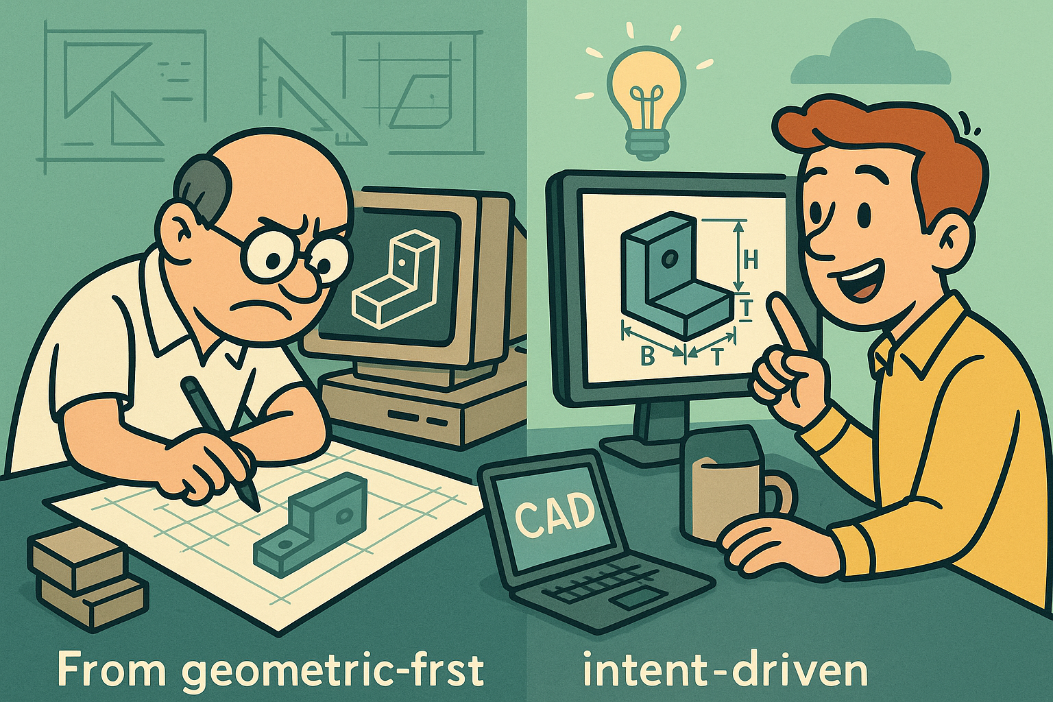
Design Software History: From Geometry-First to Intent-Driven CAD: Pro/ENGINEER and the Rise of Parametrics


Before Parametrics — The Late-1980s CAD Landscape and the Problem to Solve
Dominant paradigms in late-1980s CAD
The closing years of the 1980s presented a split-screen view of computer-aided design. On one side were drafting-centric 2D tools like CADAM—originating at Lockheed and later commercialized through IBM—that formalized layers, annotation, and geometric construction lines but treated geometry as drawing entities rather than a coherent, editable model. On the other side were increasingly capable 3D systems such as Computervision CADDS, Unigraphics from the McDonnell Douglas lineage (later UGS), and SDRC I‑DEAS that implemented solids using a mix of boundary representation (B‑rep) and constructive solid geometry (CSG). Each came with substantial mathematical heft: B‑rep entailed topological graphs of faces, edges, and vertices defined by NURBS and analytic surfaces; CSG composed primitives through boolean operations. Yet even with these foundations, what designers lacked was a way to encode and preserve the intent behind geometry. Features existed as a research idea—pockets, slots, ribs described semantically—but in practice they were often compiled down to raw faces and edges that lost their editability once “baked.” The period’s UNIX workstations (Sun SPARCstations, HP 9000, SGI IRIS) finally offered floating-point throughput and graphics pipelines to visualize shaded models, but software still reflected a geometry-first mindset. Without a dimension-driven, history-aware model, every change was an operation on results rather than on design reasoning. The promise of 3D was there; the plumbing of kernels and display lists worked; yet the typical workflow saw users backtracking through menus and re-creating parts of models because the system could not interpret how a change to a dimension should propagate.- Drafting-era strengths: layers, drawing standards, annotation control, and plotting pipelines.
- 3D-era strengths: B‑rep accuracy, boolean CSG composition, visualization on dedicated graphics hardware.
- Missing link: semantic, feature-based editing where dimensions and relations specify and regenerate geometry.
Pain points designers could not ignore
By the late 1980s, a familiar frustration dominated shop floors and engineering offices: geometry was brittle. Changing a hole pattern spacing in a solid could require deleting and rebuilding faces because downstream fillets collapsed or boolean histories got invalidated. Dimensions annotated on drawings were merely measurements; they did not “drive” the model. Large assemblies suffered from fragile mating references, and top-down design was improvised with ad hoc layer schemes and naming conventions rather than a systematic control of interfaces. Teams struggled with variability: product families were tracked in spreadsheets and job travelers, not in models that could instantiate options via parameters and rules. In assemblies, edits were weakly coupled: a sketch’s underlying entities did not consistently survive reordering, and planar references disappeared when parents changed topology, amplifying rework costs. This brittleness was not just a usability complaint; it was an economic drag that elongated ECO cycles and forced conservative decisions late in programs. The absence of true design intent meant that designers encoded outcomes rather than constraints, losing the opportunity to formalize how a part should adapt across sizes, materials, and manufacturing routes. Engineers knew what they wanted—holes that stay concentric when diameters change, ribs that maintain draft and thickness when bosses move—but lacked a system that could regenerate those relationships. Many organizations doubled down on drawing discipline and peer review, but the underlying limitation remained: without dimension-driven models, edits were ripple effects managed by people, not reliably computed by software.- Non-driving dimensions: numeric annotations disconnected from model regeneration.
- Fragile references: faces and edges renumbered or deleted through edits, breaking features and mates.
- Assembly challenges: limited top-down control and error-prone change propagation across subassemblies.
- Configuration chaos: options managed outside CAD instead of within a parametric, rule-based framework.
Seeds of change in research and hardware
While production CAD systems wrestled with brittleness, academia and advanced development labs were cultivating the ideas that would soon redefine the discipline. At MIT, David T. Gossard and colleagues were exploring variational geometry: treating sketches as systems of constraints—distances, perpendicularity, tangency—solved to find consistent configurations. In Europe, work around feature semantics and volumetric interactions (e.g., at INRIA and IBM Research) sketched how manufacturing features could be promoted to first-class modeling constructs. In Cambridge, John Owen’s D‑Cubed would emerge in 1989 as a dedicated constraint solver house, eventually providing the 2D DCM constraint manager licensed by multiple vendors. This algorithmic shift—graphs of constraints solved by geometric and numeric methods (including Gauss‑Newton variants and combinatorial decomposition)—aimed to turn drawings into computable specifications. Meanwhile, UNIX workstations standardized on higher-performance floating point and raster operations, making real-time shaded interaction and regeneration plausible for mainstream use. SGI’s IRIS GL and later OpenGL pipelines, Sun’s SPARC acceleration, and HP’s PA‑RISC machines provided the horsepower to repeatedly rebuild models as a user edited. This convergence of solver research and workstation performance framed a clear opportunity: bind feature semantics and constraints to 3D operations, maintain an ordered history of edits, and create regeneration algorithms that give dimensions authority over geometry. The pieces were aligned; what remained was an ambitious commercial implementation that treated intent—not just shape—as the nucleus of the CAD system.- Variational/constraint-based sketching research established the mathematical framework for driven geometry.
- Feature semantics matured from papers into prototypes, pointing toward manufacturable building blocks.
- UNIX workstations unlocked interactive 3D and iterative regeneration at usable latencies.
Pro/ENGINEER’s Breakthrough — Feature-Based, Dimension‑Driven Modeling as a System
Founding vision and team that operationalized intent
Parametric Technology Corporation (PTC) was founded in 1985 by Dr. Samuel P. Geisberg, a veteran of Computervision who had seen firsthand the limitations of geometry-first workflows. Geisberg’s central premise was deceptively simple: turn dimensions and relations into the primary description of the model and treat geometry as the result of continuous regeneration. The early business leadership of CEO Steven C. Walske gave PTC the commercial discipline to target high-value mechanical design accounts, while engineering leaders—later including Mike Payne—drove the technical ambition of the product. Around 1988, the first releases of Pro/ENGINEER crystallized the philosophy of design intent into a cohesive system. Unlike incremental features in competitors, PTC made features and their order a central, unavoidable concept, exposed through the now-ubiquitous model tree. The workflow taught users to select datum planes and axes as stable references, define sketch constraints, add dimension-driven features (extrudes, cuts, holes), and then leverage relations to encode how these dimensions relate. Crucially, this was not a toolkit bolted on to existing geometry engines; it was an integrated strategy that stitched together feature semantics, a parametric solver, and regeneration management with a consistent UI. In an era still dominated by UNIX, PTC’s workstation focus signaled performance credibility, while the product’s thesis resonated with engineers tired of rework: change the number, not the model.- Founder: Dr. Samuel P. Geisberg, bringing a radical rethinking of CAD fundamentals.
- Business leadership: Steven C. Walske, aligning product vision with market entry strategy.
- Engineering leadership: Mike Payne and teams integrating parametrics into a consistent architecture.
- Philosophy: features and dimensions first; geometry as a regenerated consequence.
Core technical innovations that changed daily work
Pro/ENGINEER’s breakthrough lay in its cohesive stack of innovations. The system enforced history- and feature-based modeling: an ordered sequence where each feature—protrusions, cuts, rounds, chamfers, drafts, holes—carried parameters, references, and children. The parametric constraints paradigm meant that dimensions were variables with names, equations, and units; relations linked them so a boss height could always equal, say, 1.5 times a wall thickness. Regeneration became a first-class operation, recomputing the model in tree order and surfacing conflicts for resolution. PTC paired this with robust 2D sketching: coincident, parallel, perpendicular, tangent, and equal constraints, plus over-constraint detection and automatic constraint inference. Datums—planes, axes, points—were privileged so users could avoid anchoring to transient faces, improving stability. At the assembly level, Pro/ENGINEER treated assemblies as first-class citizens with mating constraints, references, and even top‑down “skeleton” models that described the layout and interfaces feeding multiple parts. The configuration layer was equally ambitious: Family Tables enabled systematic part and assembly variants, Relations computed rule-based attributes, and Pro/PROGRAM embedded logic—IF statements, parameterized patterns—so that a single master model could instantiate a product family.- Feature ordering and dependencies surfaced in a navigable model tree with parent/child visibility.
- Equation-driven design through named parameters, units, and Relations.
- Sketch constraint solving integrated tightly with 3D feature creation.
- Assembly intent via mating, reference control, and skeleton-driven top-down design.
- Configuration mechanisms: Family Tables and Pro/PROGRAM for design automation.
Platform, kernel integration, and workflow breadth
PTC’s architectural bet was to keep the parametric engine, geometry kernel, and user interface in tight concert. Rather than adopt a third-party solid kernel such as Parasolid (by Shape Data, later Siemens) or ACIS (by Spatial, founded by Dick Sowar), PTC developed and later branded its proprietary geometric stack as Granite. This let the company tune regeneration behaviors, face identity schemes, and feature operations without kernel boundary friction. Initially focused on UNIX workstations from Sun, HP, and SGI, PTC expanded to Windows NT as PCs matured, seizing a cost/performance inflection that broadened adoption. Around the core modeler, PTC built a larger workflow story. Pro/INTRALINK introduced early product data management with version control, permissions, and reference tracking for assemblies. By 1998, PTC launched Windchill, one of the first web-based PLM platforms, extending CAD data into change management, configuration control, and enterprise-wide collaboration. On the analysis side, the 1995 acquisition of Rasna brought advanced simulation and design optimization—integrated as Pro/MECHANICA—coupling parametric models with associative analyses. Manufacturing modules like Pro/NC and Pro/MFG pulled toolpaths and process planning closer to the model, supporting the ambition that the CAD artifact would be the backbone for CAE and CAM as well.- Proprietary kernel integration through Granite for tight control of geometry and parametric behavior.
- UNIX to Windows NT transition, expanding reach without sacrificing regeneration performance.
- Data backbone: Pro/INTRALINK to Windchill for PDM/PLM continuity.
- CAE and CAM integration: Rasna’s technology as Pro/MECHANICA; Pro/NC and Pro/MFG for manufacturing linkage.
A cultural shift: design intent and regeneration as industry language
Pro/ENGINEER did more than add features; it rewired how teams spoke about design. Terms like design intent, regeneration, and feature suppression became part of daily standups. Late-stage change—once a source of dread—became a capability to boast about, provided that references were chosen wisely and design intent was encoded. The discipline of using datum schemes, selection intent, and stable reference strategies spread from PTC training rooms into the broader industry. Vendor demos across competitors began to emphasize changing a single dimension and watching assemblies ripple correctly; the narrative moved from “we can model this shape” to “we can control how this design changes.” In education, curricula began to teach constraints, parameters, and the logic of dependencies; professional certifications echoed that language. Even the user interface conventions—the ordered tree, rollback to a pre-feature state, regen failure diagnostics—propagated across products, forming a lingua franca that made it easier for designers to switch tools without losing mental models. Perhaps most importantly, the model tree became not just a UI widget but a knowledge artifact: a record of intent, rationale, and assumptions embedded in feature order and relations. PTC operationalized a philosophy and, in doing so, set the expectations against which all subsequent mechanical CAD would be measured.- Shared vocabulary centered on intent and controlled change.
- Training emphasized datum strategy, reference stability, and relation-driven design.
- UI patterns—ordered trees, rollback, diagnostic regeneration—became industry standards.
Industry Ripple Effects — Competitors, Standards, and the Hybridization of Modeling
The fast followers and challengers
The 1990s witnessed a cascade of responses to PTC’s lead, each adding its own twist. SolidWorks, founded in 1993 by Jon Hirschtick with early technical leadership from Mike Payne and a team including Scott Harris and Dave Corcoran, delivered a Windows‑native, parametric, feature-based system that leveraged the Parasolid kernel and D‑Cubed constraint managers. This combination democratized PTC’s paradigm by pairing it with familiar Windows conventions and lower hardware costs, accelerating adoption across small and medium manufacturers. Dassault Systèmes, whose CATIA V4 had dominated complex surfacing and aerospace on UNIX, answered with CATIA V5—a modernized architecture embracing Windows, integrated parametrics, and a richer application platform built around its CGM kernel. UGS/Unigraphics, later Siemens Digital Industries Software, evolved Unigraphics into NX, unifying technology from SDRC I‑DEAS after the early‑2000s consolidation. The acquisition of D‑Cubed by UGS made its 2D DCM and 3D DCM solvers a de facto industry standard, licensed broadly by SolidWorks, Autodesk Inventor, Solid Edge, and others. Autodesk, long the 2D juggernaut, entered 3D parametrics seriously with Inventor in the late 1990s, offering an approachable on-ramp for AutoCAD users seeking modern modeling without leaving the Windows ecosystem. The collective result was not just competition but a codification of the paradigm: a model tree, dimension-driven features, constraint-based sketches, and assembly mating became table stakes, with vendors differentiating on usability, performance, and ecosystem breadth rather than on the existence of parametrics itself.- SolidWorks: Windows-native parametrics using Parasolid and D‑Cubed; rapid market democratization.
- Dassault CATIA V5: modern parametrics atop the CGM kernel and a broader enterprise integration story.
- UGS/Siemens NX: unified Unigraphics and I‑DEAS; D‑Cubed solvers as widely licensed infrastructure.
- Autodesk Inventor: late‑1990s entry that brought feature-based modeling to Autodesk’s vast user base.
Strategic acquisitions and the move toward hybrid modeling
As parametrics became mainstream, consolidation reshaped the vendor landscape and set the stage for hybrid approaches. PTC’s 1998 acquisition of Computervision consolidated substantial customer bases and legacy technologies under one roof, reinforcing PTC’s position across industries transitioning from CADDS and other platforms. In 2007, PTC acquired CoCreate—the descendant of HP’s SolidDesigner and an emblem of direct modeling—adding a mature, history‑free paradigm to its portfolio. This set the groundwork for Creo’s Flexible Modeling, which brought direct manipulation and topology edits into a history-based environment without discarding the model tree. In 2010, PTC rebranded Pro/ENGINEER to Creo, signaling a future intent to embrace both parametric and direct modeling under one brand, offering users the choice of tool for the task at hand. Siemens had heralded a similar convergence with its Synchronous Technology in Solid Edge and NX, blending constraint-based intent with direct face edits and live rules. Dassault evolved CATIA and SolidWorks to include more direct editing aids while preserving parametric workflows. The industry learned a pragmatic lesson: users want the control of a history-driven model when encoding design intent, and the speed of direct edits when exploring or importing imperfect geometry. The strategic moves were less about headlines and more about aligning product capabilities with the reality of continuous change, supplier data variability, and compressed program timelines.- PTC + Computervision (1998): consolidation of legacy bases and technology migration paths.
- PTC + CoCreate (2007): infusion of direct modeling, enabling Creo’s Flexible Modeling.
- Rebrand to Creo (2010): explicit embrace of hybrid parametric + direct futures.
- Industry convergence: Siemens Synchronous Technology and Dassault’s direct-edit aids converged on similar goals.
Technical and UX consequences that defined the next decade
As feature-based parametrics spread, a set of hard technical problems became the focus. Chief among them was the topological naming problem: when geometry changes, face and edge identities shift, breaking dependent features and assembly mates. Vendors responded with a mix of heuristics (geometric and topological matching), intent references (e.g., axis of cylindrical patch rather than a specific face ID), selection intent sets, and robust datum strategies. Constraint solver ecosystems bifurcated: PTC kept proprietary solvers closely tied to Granite and its regeneration engine, while D‑Cubed’s 2D/3D solvers became widely licensed, fostering interoperability and a vibrant plug‑in market. Scaling assemblies introduced performance and data management challenges. Lightweight representations (e.g., JT from UGS/Siemens, 3DXML from Dassault), partial loading, and level‑of‑detail techniques became essential. PDM/PLM integration transformed from add‑on to baseline: reference integrity across versions, configuration rules for complex variants, and effectivity management became expected. Standards like STEP AP203/AP214 improved interchange, but the richest intent—relations, feature semantics—remained challenging to exchange faithfully. UX also evolved: diagnostic dashboards for regen failures, replay and rollback controls, and enhanced patterning and mirroring tools aimed to reduce the cost of change. Though none eliminated brittleness entirely, they reframed it as an engineering consideration manageable with the right modeling practices.- Persistent naming strategies: geometry matching, intent references, and datum‑first practices.
- Solver ecosystems: proprietary (PTC) vs. licensed (D‑Cubed) shaped vendor roadmaps and interoperability.
- Large-assembly realities: lightweight formats, partial loading, and PLM-driven configuration governance.
- Standards progress: geometry exchange improved, while feature semantics remained vendor-specific.
The long arc back to PTC through the cloud
The 2010s introduced a new platform shift: the browser and the cloud as serious venues for professional CAD. Onshape—founded by Jon Hirschtick, John McEleney, Mike Payne, and colleagues—reimagined feature-based modeling with a cloud-native architecture. It preserved parametric assemblies, sketches, and features while embedding real‑time collaboration, branching/merging, and document versioning that felt more like Git than traditional PDM. A server‑side kernel and a modern constraint engine enabled updates without client installs; FeatureScript exposed parametric feature creation to users as code, opening a community layer akin to spreadsheets for geometry. Importantly, the platform eliminated file-based conflicts by design, treating the model as a live database with granular access control. In 2019, PTC acquired Onshape, closing a historical loop from workstation-era parametrics to cloud-native, versioned collaboration under the same corporate umbrella that had first operationalized design intent at scale. The move signaled not just a product addition but a strategic acknowledgement: the future of parametrics involves solving old problems—model robustness, persistent naming, multi‑user concurrency—on new infrastructure. With Creo evolving toward hybrid modeling on desktops and Onshape advancing collaborative parametrics in the cloud, PTC positioned itself across both ends of the spectrum, betting that the next wave would be less about isolated features and more about connected workflows, instant deployment, and analytics‑driven design feedback.- Onshape: browser-based parametrics with real-time collaboration and versioned branching.
- FeatureScript: user-extensible features that treat geometry creation as programmable intent.
- PTC’s 2019 acquisition: reunites early parametric vision with cloud-native delivery.
Conclusion
What Pro/ENGINEER changed—and why it still matters
Pro/ENGINEER did not invent every ingredient of parametric modeling, but it was the first to operationalize them as a coherent commercial system. By putting dimensions, relations, and regeneration at the center, PTC made late changes tractable and routine. The model tree elevated process into an artifact, exposing how a part was built and how it should adapt. Assemblies ceased to be collections of solids and became living networks of mating intent and skeleton-driven interfaces. Configuration tools—Family Tables and Pro/PROGRAM—let a master model author a family, not just a part. This redefinition forced competitors to match the paradigm, leading to industry-wide standardization around constraint solvers, feature semantics, and regeneration workflows. Just as important, Pro/E catalyzed the tightening of CAD with CAE, CAM, and PLM: simulation became associative, toolpaths stayed synchronized, and change management matured from file check-in/out to enterprise process control. Today, even as tools diverge in kernels or UX, the expectations endure: a designer should capture intent once, edit by changing values or rules, and rely on the system to rebuild without mystery. That expectation—geometry as a computable, revisable specification—is the lasting legacy of PTC’s early vision and the baseline from which every modern mechanical CAD system now argues its differentiation.- Intent-centric modeling: dimensions and relations drive geometry, not the other way around.
- Tree-structured histories: readable, auditable records of design processes and dependencies.
- Enterprise backbone: CAD linked tightly with CAE, CAM, and PLM for lifecycle continuity.
From history-based to hybrid to cloud-native: the road ahead
The contemporary landscape inherits Pro/E’s core ideas while targeting enduring pain points. Hybrid modeling—combining history-based parametrics with direct editing—acknowledges the multiplicity of workflows across concept, supplier data reuse, and late-stage fit and finish. Persistent naming remains an active research and engineering frontier; advances in semantic references, volumetric matching, and constraint graph resilience continue to reduce brittleness. Cloud-native platforms extend the paradigm with real-time collaboration, scalable compute for regeneration and simulation, and versioning frameworks that treat models as living branches rather than serialized files. Beyond infrastructure, the coupling of generative methods and parametrics promises a loop where constraints and objectives guide automated exploration, yet final designs remain editable and governed by human-authored intent. The likely end state is not a replacement of parametrics but its enrichment: models that are richly constrained, robust to change, aware of manufacturing and inspection through model-based definition, and continuously integrated with enterprise data. In that world, the ethos that Pro/ENGINEER introduced—edit the number, preserve the idea, regenerate with confidence—becomes the connective tissue from concept through production, whether running on a workstation, in a browser, or across a distributed cluster orchestrating simulations and toolpaths. The tools evolve; the principle of intent-driven geometry endures.Also in Design News