Your Cart is Empty
Customer Testimonials
-
"Great customer service. The folks at Novedge were super helpful in navigating a somewhat complicated order including software upgrades and serial numbers in various stages of inactivity. They were friendly and helpful throughout the process.."
Ruben Ruckmark
"Quick & very helpful. We have been using Novedge for years and are very happy with their quick service when we need to make a purchase and excellent support resolving any issues."
Will Woodson
"Scott is the best. He reminds me about subscriptions dates, guides me in the correct direction for updates. He always responds promptly to me. He is literally the reason I continue to work with Novedge and will do so in the future."
Edward Mchugh
"Calvin Lok is “the man”. After my purchase of Sketchup 2021, he called me and provided step-by-step instructions to ease me through difficulties I was having with the setup of my new software."
Mike Borzage
Streamline Engineering with PTC Creo: From AI-Driven Design to Real-Time AR Integration
June 27, 2025 6 min read


Introduction
Compressed launch windows, global supply chain volatility, and heightened sustainability demands collectively squeeze contemporary development schedules. PTC Creo has responded with a slate of innovations that weave automation, analytics, and cloud reach directly into the CAD canvas, enabling engineering teams to stay ahead of the curve rather than merely react to it.
Model-Based Definition (MBD) 4.0 Enhancements
The most visible change in the latest release is the maturation of Model-Based Definition into a fully semantic product specification. Geometric Dimensioning and Tolerancing annotations are no longer static text but database entities that other applications can query, validate, and execute against.
Semantic PMI provides three tangible accelerators. First, 2D drawing packages fade into the background because every downstream participant consults the source model. Second, machinists and quality teams import the precise GD&T without re-keying, a traditional quality leak. Third, procurement portals feed the machine-readable tolerances straight into supplier RFQ algorithms, creating apples-to-apples quotations in seconds.
Creo’s automated checks against ASME Y14.41 and ISO 16792 noticeably reduce compliance workloads. Clicking “Validate” returns a color-coded dashboard showing pass, warn, or fail status for each annotation; auditors attach the resulting HTML report directly to PLM records, shrinking review meetings to confirmation sessions.
The real superpower is downstream reuse. CAM toolpaths now pick up true-position callouts, and coordinate-measurement-machine routines load the same datum schema, giving quality engineers confidence that what was designed is exactly what will be inspected. Even supplier collaboration benefits—secure web viewers honor the embedded combination states, meaning the correct view, annotation layer, and simplified rep appear by default.
To make the transition smooth, create libraries of combination states tailored to persona—one for CNC programmers, one for inspection, another for marketing. Roll them out via start-part templates rather than user training sessions. In practice, this approach turns MBD from an abstract initiative into a default behavior that quietly removes hours of drawing translation from every release cycle.
- Machine-readable GD&T eliminates transcription errors and closes quality loops.
- Automated standards validation trims audit time from days to minutes.
- Persona-based combination states package the right view and annotation set for each stakeholder.
AI-Driven Generative Design Extension
Generative algorithms once demanded niche expertise and workstation clusters. With the new Creo Generative Design Extension (GDX), they occupy the same toolbar as Extrude and Hole. The engineer defines functional goals—weight target, maximum displacement, manufacturing budget—and presses “Generate.” In minutes, cloud horsepower returns scored geometry alternatives, ranked by the multi-objective metric you choose.
Because users embed manufacturing constraints into the solve, the resulting shapes carry design for manufacturability baked in. Whether your shop makes castings, five-axis machined billets, or powder-bed metal prints, GDX respects minimum wall thickness, global draft, and tool clearance as immutable boundaries. This avoids the frustrating cycle of concept-to-DFM rejection that plagues traditional topology optimization.
For organizations that guard workstation capital budgets, cloud bursting shifts solve costs into an operational model. Engineers queue studies at 5 p.m. and review candidates with coffee the next morning, regardless of laptop GPU count. IT only manages user authentication; PTC maintains elastic nodes across multiple regions under strict ISO 27001 controls.
Data emerging from early deployments highlight measurable gains: 30–50 % mass reduction on structural brackets, intake manifolds, and battery trays, with concept selection finalized 20 % faster. Instead of engineers iterating designs manually, they evaluate system-generated trade studies, freeing attention for requirements negotiation and cost modeling.
Integrating GDX into existing workflows is straightforward. Store constraint envelopes and load conditions in a template file to ensure each part family receives consistent boundary conditions. Configure naming rules so generated candidates land in a “Concepts” subfolder, avoiding PLM clutter. Finally, route the winner into the normal design release track, where MBD, simulation, and manufacturing steps proceed unaltered.
- Goal-driven algorithms explore thousands of permutations without human fatigue.
- Manufacturing constraints enter the solver up front, eliminating late-stage rework.
- Elastic compute removes the need for local hardware scaling cycles.
Creo Ansys Simulation Live – Real-Time Multiphysics Feedback
Continuing the theme of collapsing hand-offs, Creo Ansys Simulation Live embeds a GPU-accelerated solver directly in the modeling environment. Change a fillet radius and stress plots update in under a second, encouraging experimentation that would have previously required an analyst’s queue time.
The feedback is not limited to static structural metrics. Modal frequencies, thermal gradients, and even basic fluid proxies run concurrently. The interface highlights tolerance-sensitive zones, prompting designers to thicken ribs or re-locate bosses while the cursor still hovers over the feature tree. Because each iteration costs pennies in compute time and zero queue overhead, teams uncover optimal performance envelopes long before formal validation.
Capturing corporate knowledge is easier than ever through template studies. For example, define a “Pump Housing” study with default boundary conditions: 5 MPa internal pressure, ambient 80 °C, and mounting bolt loads. Expose the study in the start-part. A new designer edits geometry and instantly sees stress redlines without remembering load vectors or units. Quality managers appreciate consistent margin calculations, and mentorship time shifts from “how to set up FEA” to “why the design matters.”
Real-time simulation does not replace high-fidelity sign-off analysis; rather, it prunes unviable paths at the white-board stage. Organizations that lead with this approach routinely report multi-day compression per design loop. Perhaps more importantly, they cultivate a culture where performance decisions occur in tandem with form-giving rather than as an after-the-fact approval gate.
- GPU-accelerated solvers refresh stress, modal, and thermal plots in real time.
- Embedded color feedback guides designers toward performance-driven edits.
- Template studies institutionalize best practices across part families.
Additive Manufacturing Suite and Lattice Toolkits
Once generative design proposes a radical shape, manufacturing feasibility becomes the next hurdle. Creo’s Additive Manufacturing Suite removes that barrier by folding printer awareness and lattice generation into the core model. Unlike plug-ins that export a mesh for third-party editing, Creo maintains a parametric relationship, meaning a dimensional tweak propagates through the lattice and support structures automatically.
The toolkit includes ready-made Unit Cells—gyroid, diamond, Schwartz, and beam networks—but also allows custom scriptable cells for specialized acoustic, thermal, or biomedical properties. Applying a lattice is as simple as selecting a volume and assigning a density gradient. The software maps material where load paths dictate and trims weight elsewhere, respecting minimum strut thickness and printer resolution.
Build-volume simulation deserves special mention. Orientation, slicing, and support strategies feed a real-time preview of recoater forces, residual stress, and potential warpage. Designers pivot orientation or tweak local wall angles before exporting the .AMF or .3MF job file, reducing first-print failures that can cost thousands in powder waste and machine downtime.
Because each major printer OEM now offers a Creo profile, the hand-off is essentially one click. Generate the support tree, nest multiple parts, and embed metadata like machine, material batch, and scan strategy—all tagged inside the Creo model for PLM traceability. Quality teams later correlate CT-scan results or tensile coupons back to the exact geometry version, closing the loop from design to inspection without digital dead ends.
- Native lattice libraries enable lightweighting without external meshing software.
- Build-volume simulation predicts warpage and support needs prior to print.
- Printer-specific profiles ensure export is truly “print-ready.”
Augmented Reality and IoT-Connected Digital Thread
Even the most optimized part must eventually meet users, technicians, and managers. Creo’s integration with Vuforia and ThingWorx extends the 3D model beyond the workstation and into the plant, the field, and the boardroom.
A single toolbar button publishes the active model as an AR experience. The tool generates a constrained anchor, compresses geometry into a secure package, and emails a persistent URL. Anybody with a smart device scans a QR tag and views the assembly at scale, no app installation required. For troubleshooting, you can ghost the housing and highlight fasteners, dramatically shortening training curves.
The value amplifies when IoT sensors stream live telemetry back onto the same model. Pressure, vibration, or temperature readings overlay color gradients in the viewer, allowing engineers to correlate field anomalies with digital twins in real time. Decision makers visualize not abstract numbers but data-enriched geometry, accelerating root cause analysis.
Collaboration workflows also gain efficiency. AR snapshots capture annotations—dimension tweaks, clearance concerns, cosmetic feedback—and store them in PLM as lightweight markups. Instead of convening weekly design reviews around slide decks, stakeholders asynchronously review and accept tasks, a shift that can erase double-digit meeting hours per project.
Security remains paramount. By leveraging Azure or AWS regions that meet FedRAMP or ITAR controls, organizations restrict geometry access to named users. Granular role settings control whether a supplier can explode the assembly or simply view a shrink-wrapped representation, striking a practical balance between openness and IP protection.
- One-click AR publishing democratizes 3D visualization for non-CAD audiences.
- Live sensor overlays create a closed feedback loop between field performance and design intent.
- Role-based access and cloud region controls keep proprietary data secure.
Conclusion
PTC Creo’s recent advances form a coherent, end-to-end acceleration stack. Model-Based Definition transforms annotations into authoritative digital specifications. AI-driven generative design explores vast solution spaces within manufacturing constraints. Real-time multiphysics simulation eliminates serial hand-offs and empowers on-the-spot refinement. Additive-ready latticing ensures radical geometries print correctly the first time, and AR-enabled digital threads close the feedback loop with in-service insights.
Early adopters report double-digit reductions in lead time and non-recurring cost, gains that compound with each product cycle. Evaluate targeted pilot projects—a lightweight bracket, a thermally stressed housing, a field-service training module—to experience these benefits firsthand. The competitive landscape will not slow down; embedding these capabilities now positions your organization to out-innovate and out-deliver long before the next market window opens.
Also in Design News

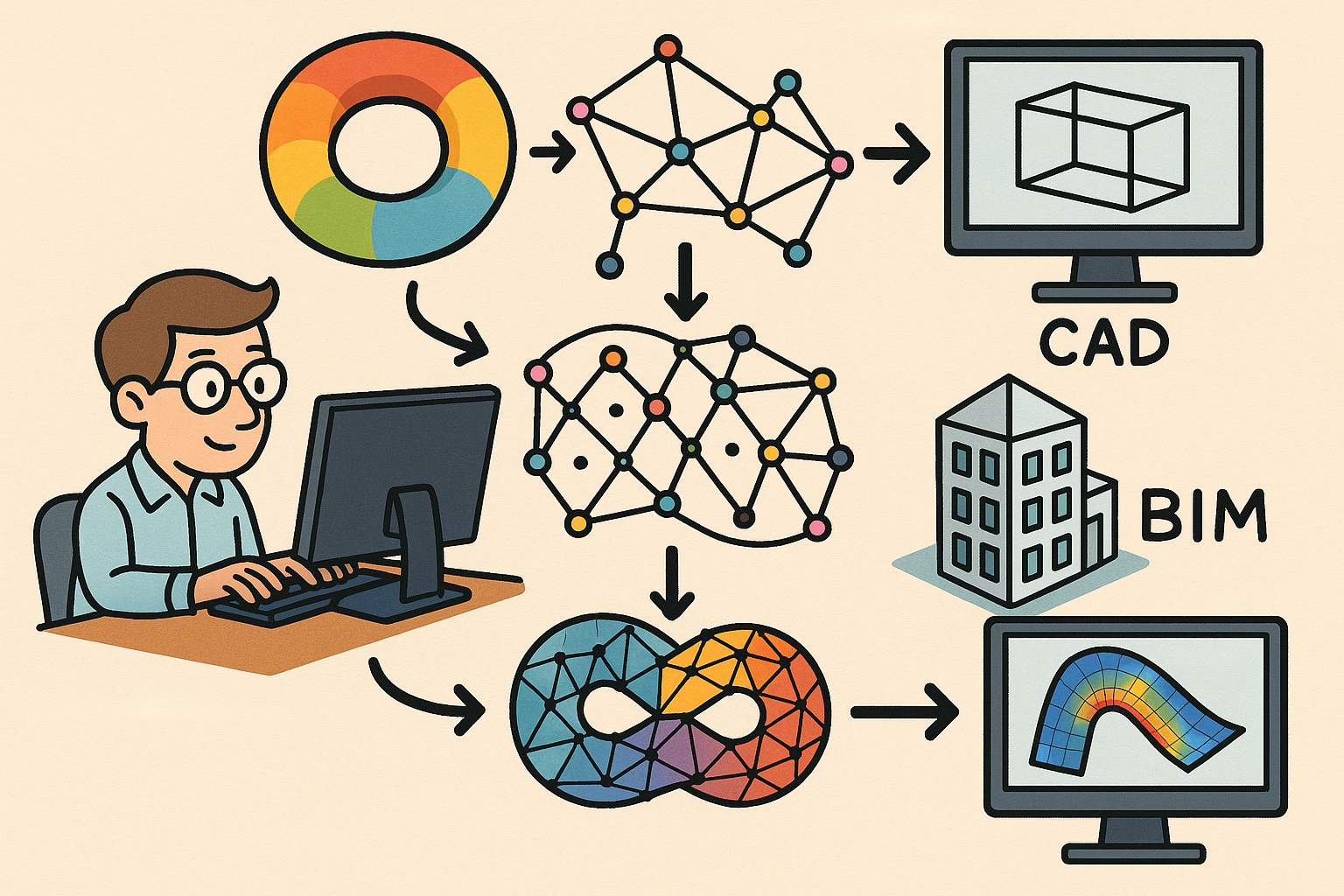
Design Software History: From Computational Topology to Design Software: Integrating TDA into CAD, BIM and CAE Workflows
December 25, 2025 10 min read
Read More
Scene-Aware LOD: Perception-Driven Fidelity for Scalable Design Visualization
December 25, 2025 12 min read
Read MoreSubscribe
Sign up to get the latest on sales, new releases and more …


