Your Cart is Empty


Rhino 3D Tip: Precision Cone and Frustum Modeling in Rhino
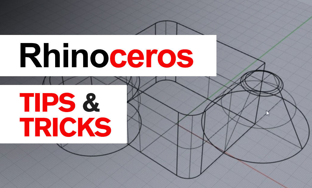

Use Rhino’s Cone command to create both pointed cones and truncated cones (frustums) with precise control over base size, top size, height, orientation, and solid closure. It is an efficient starting point for product-design forms, architectural components, funnels, lampshades, transition pieces, mechanical reducers, and fabrication-ready solids.
Start the command by typing Cone and choose a base definition method. The most common workflow is to define the base center and radius, then specify the cone height. Rhino lets you enter exact values directly, so a cone can be built accurately without relying on approximate viewport picks.
- Base center: Place the cone precisely using object snaps, coordinates, or an existing construction plane.
- Base radius: Enter a numerical radius or pick a point visually.
- Height: Set the cone height by clicking or typing an exact value.
- Direction: Define the height in any 3D direction, not only perpendicular to the active CPlane.
For a traditional pointed cone, set the top radius to zero. For a truncated cone, specify a non-zero top radius when Rhino prompts for it. This creates a frustum in one operation, avoiding the need to make a full cone and trim it afterward. In practical modeling, this approach is cleaner, faster, and more reliable than trimming because the result remains a simple, well-structured surface or solid.
When the command-line option is available, use Solid=Yes if you need a closed polysurface. A closed cone is immediately more useful for Boolean operations, volume calculations, 3D printing checks, and rendering. If you need only the side skin for surfacing work, set the cone to open instead. Verify the outcome with Rhino’s What command or use ShowEdges to locate naked edges before moving into downstream fabrication or Boolean workflows.
For better control, build cones from a deliberate construction plane. A custom CPlane aligned to an angled face, axis, or reference geometry enables accurate placement and reduces later transformation work. If the cone must be centered on existing geometry, activate relevant object snaps such as Center, End, Mid, and Perpendicular.
- Use
Gumballafter creation for quick visual adjustments. - Use
Move,Rotate3D, orOrient3Ptwhen exact repositioning is required. - Use
BooleanDifferenceto create countersinks, tapered holes, and conical cavities. - Use
BooleanUnionto combine cones with other closed solids. - Use
ExtractSrfif you need to isolate the lateral surface for advanced surfacing edits.
A useful modeling habit is to name or layer cones according to their purpose: “Cutters,” “Transitions,” “Draft,” or “Reference.” Keep Boolean cutter cones on a dedicated layer until the design is approved. This preserves editability and makes revisions significantly easier.
When modeling objects that will be manufactured, remember that a truncated cone often represents draft angle rather than a purely visual form. Entering accurate top and base radii lets you control that taper predictably. For additional Rhino training resources, software options, and professional design tools, visit NOVEDGE. You can also explore the Rhino collection at NOVEDGE for Rhino-related products and workflow resources.
You can find all the Rhino products on the NOVEDGE web site at this page.
Also in Design News