Your Cart is Empty
Manufacturability-Driven Topology Optimization for Additive and Hybrid Manufacturing


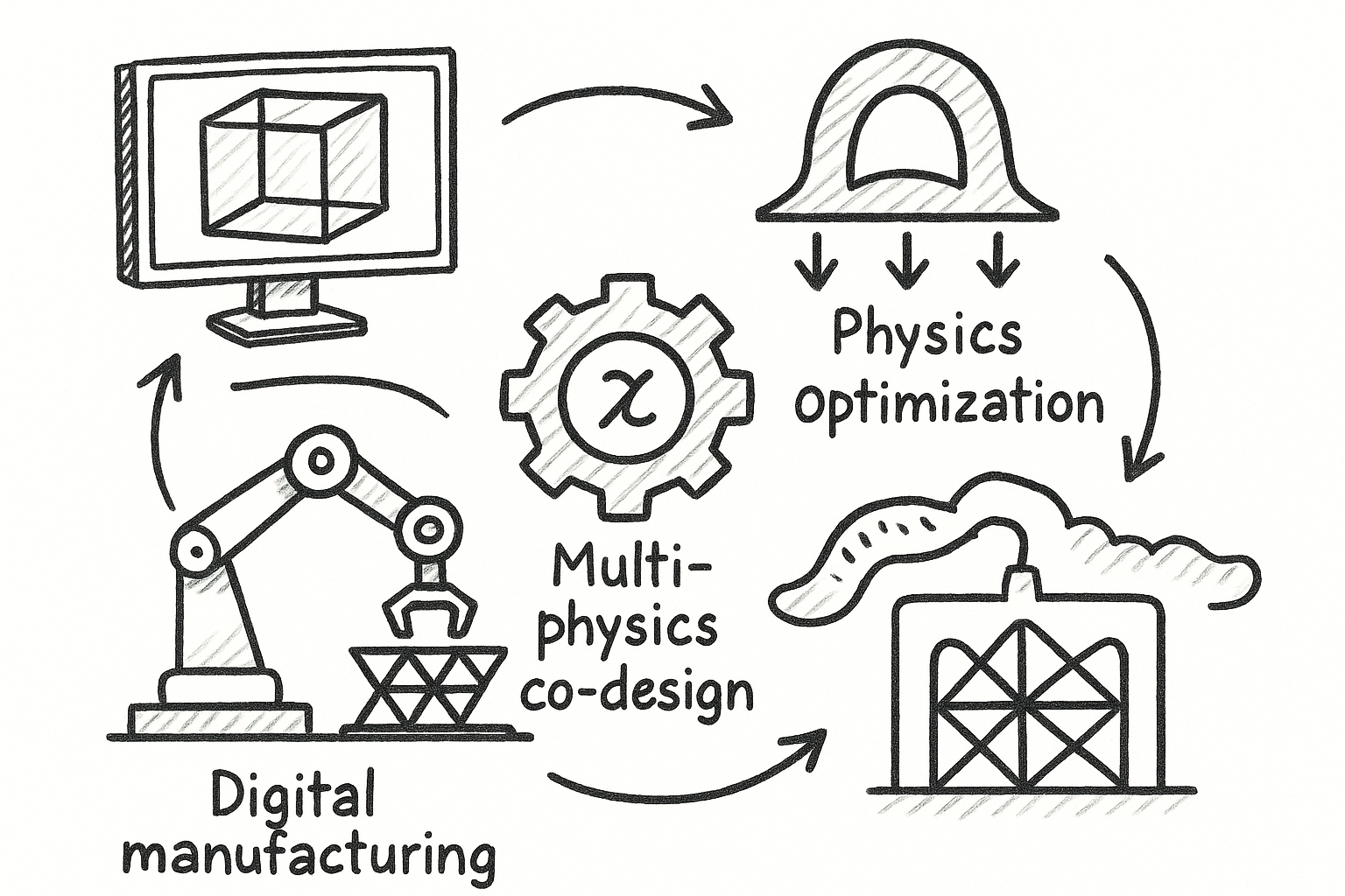
Why Manufacturability Now Defines “Optimal”
Re-centering goals on end-to-end value
Topology optimization once equated “optimal” with peak stiffness-to-weight, but that lens is too narrow for additive and hybrid manufacturing realities. A part that wins a numerical objective yet fails on the build plate, needs hours of aggressive support removal, or demands costly rework is not optimal in any meaningful sense. The objective has to expand to the full production lifecycle: predicted **support volume and contact area**, orientation-dependent **build time**, post-processing labor, and the **probability of print success** under process variability. Each factor connects directly to cost, schedule, quality, and sustainability. Broadening the goal does not dilute engineering rigor; it strengthens it by embedding **manufacturability** as a first-class requirement. That means we deliberately trade a small amount of structural efficiency for dramatic gains in yield and throughput. It also means quantifying “quality” numerically—surface roughness bands by face class, geometric conformance versus as-printed deviation, and residual stress envelopes that correlate to straightness and flatness. When these terms sit alongside compliance or frequency objectives, the optimizer stops producing fragile art and starts delivering production-ready geometry. In practice, wrap your topology run in a cost surrogate that aggregates these considerations, normalize each term to comparable scales, and let the solver responsibly arbitrate trade-offs rather than forcing a late-stage, error-prone manual reconciliation.
- Augmented objective: structural performance + support/contact + build/finish + success likelihood.
- Quantified quality: roughness targets, geometric deviation, residual stress limits.
- Outcome: parts that print consistently, finish fast, and meet performance with margin.
Orientation as a design variable, not an afterthought
Part orientation dominates additive outcomes, so treat **build orientation** as a design variable tightly coupled to shape. Rotating a candidate can cut support volume by half, shorten recoater travel, reduce thermal gradients, and vastly improve upskin/downskin roughness—all while changing mechanical anisotropy in critical regions. The right approach is to weave orientation into the optimization loop, not to sweep it at the end. Orientation controls which faces become overhangs, how heat flows to the baseplate, where the first solidification occurs, and where stress accumulates. But the trade-offs are subtle: a perfect support-minimizing angle may place a fatigue-critical rib in a weak direction relative to scan tracks. Incorporate an orientation parameterization (Euler or axis-angle), a support and roughness surrogate, and an anisotropic material model that captures process-induced properties. Let the solver search for Pareto-efficient combinations—for example, minimal support with acceptable stiffness loss and sufficient safety factors in the principal directions. This unlocks geometry that prints with crisp overhangs, requires minimal touch points, and still meets **anisotropic mechanical performance** constraints. Do not accept a single “best” orientation; maintain a ranked front of choices and pick the one that aligns with downstream finishing and fixturing.
- Embed orientation in the solve: optimize geometry and angle together.
- Model anisotropy: direction-dependent modulus, yield, and fatigue coefficients.
- Use Pareto fronts: balance surface quality, support minimization, and strength.
Cost proxies and hard constraints that matter on the floor
Production teams need transparent levers that tie optimization decisions to shop-floor effort. Incorporate cost proxies that respond to geometry: **overhang penalties** keyed to local angles relative to the build direction; perimeter-weighted terms for support **contact area** that drive fewer, larger pads over many small touchpoints; and **minimum feature-size** enforcement to keep ligaments printable and robust. Reserve **assembly interfaces**—bolt patterns, datum planes, and sealing surfaces—as immutable hard constraints, with localized roughness and flatness targets. Add **tool access cones** for drilling, tapping, or reaming, and check that blending fillets satisfy cutter reach, with **minimum fillet radii** set by the smallest tool. Finally, reflect real station times: blast hours scale with surface area and roughness, wire EDM slotting depends on straight-line access, and inspection time scales with the number of critical features. A cost-constrained solver makes the field-to-floor transition explicit and auditable, so design intent survives the march from CAE to CAM. The result is a model that “knows” what your equipment and team can achieve, and it converges toward shapes that avoid time sinks rather than discovering them on the first article.
- Penalize overhangs and unsupported area; reward self-supporting orientations.
- Enforce feature floors/ceilings; lock interface geometry as sacrosanct.
- Encode access and cutter reach; tie objective to finishing and inspection effort.
Close the loop with process physics
Even the best geometry can drift when thermals go sideways. Integrate process feedback directly into the optimization as constraints or robust design terms. Use fast thermo-mechanical surrogates to estimate distortion and **residual stress** for each candidate, flagging warpage above fixture compliance or recoater force thresholds. Add **roughness bands** linked to upskin/downskin exposure and scan vectors, and constrain critical faces to stay within target Ra/Rz. Where direct simulation is expensive, use meta-models trained on layer-wise heat input and section thickness to forecast hotspot zones, and penalize shapes that amplify them. For robustness, embed chance constraints: maximize performance subject to a capped probability of support failure given **powder variation** or **thermal noise**. This does not demand full-fidelity co-simulation on every iteration; a two-tier approach—surrogate screening followed by periodic high-fidelity verification—keeps the loop fast and relevant. Once this feedback sits in the loop, the optimizer learns to avoid distortion-prone mass clusters, to spread heat loads along stout paths, and to keep scan lengths manageable—small choices that pay off in predictable, repeatable builds.
- Constrain distortion, residual stress, and roughness for critical faces.
- Use surrogates for speed; verify with selective high-fidelity solves.
- Adopt chance constraints to protect yield under process variability.
Encoding Manufacturability into Topology Optimization
Length-scale control with PDE filters and projections
Without explicit **length-scale control**, topology optimization happily invents lacework nobody can print, cast, or machine. Solve this at the field level. Apply density or level-set smoothing through Helmholtz-type PDE filters to enforce minimum length scales, then recover crisp boundaries with **Heaviside projections** that snap ambiguous gray regions to 0/1 while preserving gradients through continuation schemes. Complement the minimum with a maximum feature size by integrating morphological operations that erode accretions and prevent bloated plates or slabs that hinder heat flow. Beyond size, ensure **connectivity constraints** so that isolated “islands” cannot form, and enforce minimum ligament widths to avoid razor-thin bridges that warp or break under peening and handling. Tune filter radii to machine and material: for laser powder bed, set ligament floors to 2–3 times the minimum strut rule; for binder jet or DED, scale up to reflect bead geometry. When length scales are explicit, optimizers redirect complexity into regions where it is printable—thicker ribs, swept fillets, and smooth junctions—and the design space remains rich without straying into unmanufacturable artifacts.
- Use PDE filters for minimum size; morphological filters to cap maximums.
- Heaviside projections for crisp, fabricable boundaries.
- Connectivity and ligament width constraints to prevent islands and weak links.
Process-aware constraints: overhangs, supports, and tools
Make the algorithm aware of the process. For additive, implement **overhang constraints** by evaluating surface normals relative to the candidate build direction and penalizing regions exceeding critical angles. Enforce limits on unsupported area locally, not just globally, so shadowed pockets do not slip through. Augment with **support-aware penalties** that integrate predicted support volume or contact area into the objective, steering the solver toward self-supporting motifs and strategic angling. For hybrid workflows, add **machining-aware rules**: draft and draw constraints for casting, clearance for die pull, and **tool access cones** for end mills and probes. Minimum fillet radii ensure cutter reach and survivable path planning, while minimum slot widths respect tool availability. Prefer topological moves that open line-of-sight rather than generating blind cavities. The orchestration is straightforward: compute local violation fields (angle, access, radius), convert them to differentiable penalties, and let the optimizer reshape violation hotspots. You will find the solution naturally evolving toward surfaces that shed supports, ribs that meet cutters, and channels that drain and vent cleanly, aligning digital intent with physical reality.
- AM-aware normals with local overhang limits and support penalties.
- Casting/forging drafts and draw rules to guarantee extraction.
- Tool access and minimum fillet radii for CAM feasibility.
Algorithmic choices: SIMP, level-set, MMC, and robust loops
Different formulations excel at different manufacturability tasks. SIMP with anisotropic filters is fast and robust for coarse exploration and can embed directional overhang penalties efficiently. **Level-set** methods deliver crisp boundaries and pair well with curvature and overhang constraints but demand careful reinitialization. **Moving Morphable Components (MMC)** craft explicit bars, plates, and fillets as primitives, making it natural to impose minimum radii, thickness, and alignment with the build direction. For simultaneous shape and **orientation optimization**, use bilevel loops: inner solves for material layout; outer solves (or Bayesian search) over orientation with **surrogate cost models** for support, distortion, and roughness. To preserve yield under uncertainty, adopt **robust optimization**—worst-case constraints for distortion envelopes or chance constraints for support failure probability. The recipe is pragmatic: start SIMP for speed, localize promising zones, transition to level-set or MMC for boundary quality, and alternate orientation updates against process surrogates. As fidelity rises, fold in thermal-distortion checks to prune brittle optima. This stack yields designs with both numerical grace and shop-floor resilience.
- SIMP for speed and anisotropic filters; level-set for boundary control.
- MMC for explicit manufacturable primitives.
- Bilevel orientation-geometry loops with process-aware surrogates and robust terms.
Lattices and Multi-Scale, Implicit Design
Property-accurate lattices via homogenization and grading
Lattices promise mass efficiency and damping, but only if their effective properties are respected. Use **homogenization** to map unit-cell parameters—TPMS thickness, strut diameters, plate fractions—to continuum stiffness, strength, and thermal conductivity. Calibrate these maps against printable floors: minimum **strut and skin thickness** must exceed process thresholds with margin for roughness and powder sinter. With property tables in hand, perform field-driven grading of cell type and size using stress, strain energy density, or thermal gradients. Blend between cells smoothly to avoid weak seams, and apply filter-based transitions that keep manufacturing variation to a small, controlled region. Critically, the grading must not violate minimum cell feature sizes when the macro field narrows; impose lower bounds tied to cell topology to prevent “ghost” members. The pay-off is a multi-scale body where solid skins carry contact and sealing, graded cores handle bending and buckling, and high-conductivity cells drive heat to sinks—each choice grounded in printability and effective property truth rather than wishful thinking.
- Homogenize TPMS, strut, and plate lattices into continuum surrogates.
- Respect printable floors for struts/skins; include roughness allowances.
- Grade fields smoothly with filters to avoid abrupt property jumps.
Support-free microstructures and orientation-aware alignment
Self-supporting microstructures transform support from a tax to a design variable. Choose TPMS families and unit cells that satisfy the critical **overhang constraints** natively—Gyroid, Diamond, and Schwarz variants tuned so local curvature and surface slope remain above the process-specific threshold. Align cells with the **build orientation** so that their principal directions favor layer bridging and heat shedding, and control local **curvature** of implicit isosurfaces to avoid thin necking that invites balling. Incorporate a penalty for unsupported lattice area directly in the local cell parameterization; as unsupported fraction rises, thickness grows or topology shifts toward more vertical ligaments. At transitions between lattice and solid, taper cell thickness and increase volume fraction to form a robust skin-core bond line, resisting delamination during blasting and fatigue. With these rules, lattices emerge that print cleanly—no “fur” of supports in the core—while preserving the mechanical and thermal promises that motivated their inclusion.
- Use self-supporting TPMS with bounded curvature and slope.
- Align lattice orientation to build direction to minimize local overhangs.
- Taper at interfaces to secure skin-core integrity.
Hybrid architectures and an implicit toolchain
Most high-performing parts are hybrids: **solid-lattice skins**, rib-reinforced shells, and local infill switches keyed to load paths, wear zones, and fatigue life. To orchestrate these cleanly, lean on **implicit modeling**—signed distance fields (SDFs) for Booleans, offsets, and fillets without mesh scars. SDFs also excel at lattice generation: modulate unit cells across the macro field and perform robust, watertight operations for beams, plates, and shells. Export can target meshes, voxels, or implicit formats depending on the slicer’s appetite, but keep an **implicit master** to avoid STL artifacts. Verification closes the loop: replace density or level-set fields with lattice surrogates, reanalyze with detailed FE or submodeling to capture size effects and notch sensitivity, and confirm manufacturability limits like minimum hole diameters and tool approach. This toolchain stabilizes late changes—if the optimizer nudges a fillet or shifts an interface, the implicit representation updates cleanly, and downstream analysis and slicing remain consistent. The result is not just a printable part, but a robust digital thread that keeps design, simulation, and manufacturing in lockstep.
- Hybridize: shells, ribs, and graded lattices aligned to load paths.
- Use SDF-based implicits for clean Booleans, offsets, and lattice operations.
- Reanalyze detailed lattices to capture local size and notch effects.
Conclusion: Manufacturability as a First-Class Citizen
Key takeaway and a practical optimization roadmap
The critical shift is simple: treat **manufacturability** as part of the objective and constraints from the first iteration, not a post hoc triage. When overhangs, supports, access, and process physics live alongside compliance and frequency, the optimizer stops producing brittle proofs and starts generating build-ready geometry. A pragmatic roadmap accelerates adoption. Begin by enforcing **length-scale** and **overhang constraints**; this alone eliminates most failure modes. Next, add **support-aware cost**—volume and contact area—and promote **orientation optimization** so surface quality and anisotropy are traded consciously. Once this foundation is stable, step into multi-scale design with **homogenized lattices** and **implicit modeling** for robust Booleans and grading. Throughout, pair fast surrogates with periodic high-fidelity checks to keep the loop honest. This staged approach yields quick wins without overfitting to a single tool or material and builds organizational confidence that optimization is not a research indulgence but a production amplifier.
- First enforce printability basics: length scale and overhangs.
- Then embed support/contact cost and orientation decisions.
- Graduate to multi-scale lattices with homogenization and implicits.
Metrics that matter and pitfalls to avoid
Track numbers that correlate with schedule, cost, and quality. Monitor **support volume and contact area**, **overhang area** by face class, predicted **build time**, and **as-printed versus as-designed deviation** from thermo-mechanical surrogates. Record non-recurring engineering (NRE) for post-processing—hours of support removal, machining, and inspection—as a cost term. Watch the **probability of print success** under variation, not just nominal feasibility. Common pitfalls loom: neglecting **tool access** and drafts when a part will see secondary machining; selecting lattice parameters beneath printable limits; skipping the reanalysis of detailed lattice models after substituting density fields; and relying on STL-only exports that introduce geometric error. Avoid these by codifying checks as constraints or penalties and by keeping an implicit master model. When metrics are visible and pitfalls are structurally blocked, teams stop debating preferences and start optimizing with shared, quantitative ground truth.
- Report support/contact, overhang, build time, and geometric deviation.
- Account for NRE in objective; capture the full cost story.
- Avoid tool-access blind spots and non-printable lattice settings.
What’s next: co-simulation, learning, and shared kernels
The frontier is integration and speed. Real-time or near-real-time **co-simulation of thermal distortion** during optimization will compress iteration cycles and reduce reliance on conservative surrogates. **Reinforcement learning** can augment bilevel search for orientation and process parameters, discovering angle and scan strategies that classic gradient methods miss, while staying bounded by manufacturability constraints. Standardized **manufacturability kernels**—libraries that deliver overhang checks, support estimators, access cones, and curvature bounds—should become shared infrastructure across CAD, CAE, and CAM, ensuring a design evaluated in simulation behaves the same at the slicer. Finally, richer uncertainty models that capture not only powder variation and thermal noise but also machine-to-machine drift will enable **robust optimization** that transfers cleanly across fleets. The direction is clear: less manual arbitration, more physics in the loop, and more intelligent exploration of design-process space. As these capabilities mature, the definition of “optimal” will settle where it belongs—at the intersection of performance, printability, and predictable production.
- Push co-simulation into the loop to tame distortion early.
- Use learning agents to propose orientations and process settings.
- Adopt shared manufacturability kernels across design and simulation tools.
Also in Design News