Your Cart is Empty
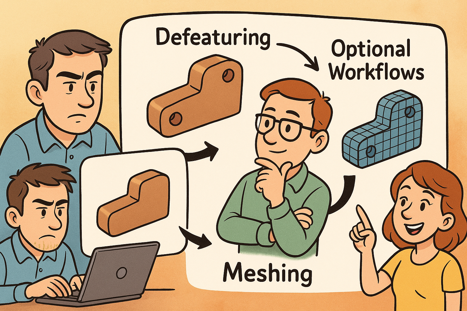
Design Software History: Defeaturing to Meshing-Optional Workflows: A Technical History of CAE Simplification


Context and scope
Why simplification matters to CAE practitioners
Computer-aided engineering has always wrestled with a fundamental tension: product geometry arrives rich in fine detail, while physics solvers prefer models tuned for stable numerics and tractable runtimes. The discipline that bridges this gap—often called defeaturing, cleanup, or abstraction—has grown from ad hoc fixes into a rigorously engineered toolbox spanning geometry kernels, meshing algorithms, and reduced-order modeling. In what follows, the focus is tight: explain how and why simplification methods evolved, who built the tools, and what technical ideas shaped the current state of practice. The goal is not stylistic nostalgia, but practical perspective—understanding where our tools came from helps teams choose methods with the right trade-offs for accuracy, speed, and scalability today.
How to read this history
The narrative moves chronologically across four arcs: limitations that forced simplification; the rise of preprocessors and geometry healing; automation and robust rules; and finally, abstraction and meshing-optional workflows. Along the way, names like NASTRAN, ANSYS, Parasolid, ACIS, and STAR‑CCM+ mark pivotal turns, while algorithmic landmarks—Delaunay triangulation, advancing-front schemes, Triangle and TetGen—reveal how geometric quality controls mesh quality and, ultimately, solution quality. Readers should watch for three recurring themes:
- Accuracy is invariant to marketing: physics demands the right scales, not all the details.
- Robustness compounds: small improvements in healing or wrapping yield outsized productivity.
- Abstraction extends beyond CAD edits: model order reduction and homogenization change what we simulate, not just how we mesh it.
Early CAE constraints
Limited compute and memory shaped modeling habits
From the late 1960s into the 1980s, analysts running NASA’s NASTRAN and the early releases of ANSYS (founded by John Swanson as SASI) worked within memory ceilings measured in kilobytes and megabytes. Batch jobs on IBM mainframes or, later, vector machines like the Cray needed sparse matrices small enough to factor overnight. The result: idealization was not optional. Thin-walled structures became shells; trusses and frames became beams; complex filleted blocks collapsed to 2D plane-stress slices. Meshes were assembled by hand in preprocessors or even coded directly in bulk data cards. The preference for regular topology—quad shells, structured grids—was less aesthetic than survival; fewer elements meant solvable problems within the night’s CPU allocation.
Geometry lived outside solvers and traveled poorly
Product geometry typically originated in CAD systems distinct from simulation tools. The IGES standard (first released in 1979) allowed surface and wireframe exchange, but splines from CATIA, Unigraphics, or CADAM often arrived as patchworks of NURBS with inconsistent tolerances. Sliver faces, tiny gaps, and non-manifold edges forced analysts to “repair” models before they could even define a volume. With solids not yet universal, and robust boundary representations still maturing, teams fell back on simplified, analyst-built geometry—clean midsurfaces, idealized cross-sections—because these artifacts meshed reliably under the day’s constraints.
Problem-driven minimalism
The era trained a generation to ask, “What’s necessary for the physics?” rather than “What can we import?” That mindset seeded practices that still hold value: isolate the load path; capture stiffness distribution with the fewest degrees of freedom; remove detail below characteristic mesh sizes. Analysts today inherit this culture of physics-aware simplification, even as compute budgets have grown by orders of magnitude.
Preprocessing emerges as a discipline
From raw cards to dedicated preprocessors
As finite element use expanded, tools like MSC (MacNeal–Schwendler) utilities for MSC/NASTRAN, PDA Engineering’s PATRAN, SDRC’s I‑DEAS, and early ANSYS preprocessors established workflows for cleanup, idealization, and meshing. These environments let users build geometry abstractions—midsurfaces for stampings, beam networks for frames—define materials and properties, and manage mesh controls. By centralizing these tasks, the industry recognized preprocessing not as clerical work, but as a separate competency where geometric and numerical insight meet.
Tolerance and topology become first-class citizens
The late 1980s and early 1990s brought the consolidation of solid modeling around Parasolid (originating at Shape Data and later part of Siemens) and ACIS (Spatial). With robust B‑Rep kernels embedded in CAD, preprocessing tools gained access to more consistent manifold solids. Still, kernel differences and translation pathways introduced tolerance mismatches. “Heal before you mesh” entered the lexicon: stitch surfaces, close gaps, merge slivers, and repair invalid edges so meshing algorithms could impose regularity. Topology healing—face merging, vertex snapping, periodic edge recognition—became codified operations rather than one-off scripts.
Industrial workflows crystallize
By the mid‑1990s, a repeatable pipeline took shape:
- Import and repair geometry with tolerance-aware healing.
- Extract midsurfaces for thin-walled parts and assign thicknesses from CAD features.
- Apply mesh controls: size fields, growth rates, and element quality thresholds.
- Export consistent model definitions to solvers with property and load mappings intact.
This regimented approach reduced variability between analysts and projects, laying groundwork for later automation.
Foundational methods
Manual defeaturing became standard craft
Early toolchains required analysts to delete tiny holes, fillets, and engravings that had negligible physical influence but lethal meshing implications. Removing 0.5 mm chamfers from a meter-scale casting might save thousands of elements and eliminate twisted slivers. Hand-extracted midsurfaces for stamped parts—trimming flanges, splitting junctions, and consistently offsetting—were hallmarks of expert practice in I‑DEAS and PATRAN. Even today, many organizations retain checklists that trace to these habits: eliminate detail below 3–5 times the target element size; collapse narrow necks to beams if stress averaging suffices; preserve only those fillets that concentrate stress in load paths.
Meshing research anchors the practice
Algorithmically, the 1990s were rich. Delaunay-based and advancing-front methods matured for triangular and tetrahedral meshes, providing guarantees on angles and element quality that mapped directly to solver stability. Two reference projects—Jonathan Shewchuk’s Triangle and Hang Si’s TetGen—became canonical, both academically and in commercial influence, demonstrating that geometry quality often dominates mesh quality. Their message remains evergreen: well-posed input with watertight topology and clean curvature yields predictable meshing; poor geometry turns meshing into trial-and-error.
Quality criteria inform simplification rules
Out of these algorithms came practical heuristics:
- Remove features smaller than the local mesh size target; do not invite elements to chase subgrid details.
- Respect curvature by locally refining or by suppressing small blends that would demand excessive refinement.
- Favor near-isotropic elements for diffusion-dominated physics; allow anisotropy when guided by flow or stress directions.
These rules built a quantitative link between defeaturing and numerical conditioning.
Commercial geometry healing and translation
Specialists industrialize topology repair
By the late 1990s and 2000s, independent vendors turned healing into productized, kernel-savvy software. ITI CADfix (International TechneGroup, later acquired by Wipro), Elysium CADdoctor/ASFALIS, and TransMagic standardized stitch-and-heal, gap closure, and small-feature suppression across IGES, STEP, and native CAD. Crucially, these tools understood kernel nuances—how Parasolid tolerances differ from ACIS, how periodic faces and analytic primitives should be recognized—and offered batch processing so large datasets could be regularized overnight.
Data pipelines become dependable
This maturing translation layer enabled a new level of reliability in supply chains. OEMs could specify target tolerances, allowed suppressions, and healing steps as vendor-neutral instructions. Healing ceased to be a fragile, per-part activity and became a repeatable data conditioning stage. That shift allowed CAE teams to spend time on physics modeling instead of chasing non-manifold edges or zero-area slivers.
Integration with PLM and revision control
Once healing was dependable, it integrated with PLM systems (Teamcenter, ENOVIA, Windchill). Automated checks ensured that incoming revisions met minimal “watertightness” and simplification criteria before analysts touched them. The result: fewer late-stage surprises and more predictable meshing lead times across programs.
Automated feature recognition and suppression
From patterns to libraries of removable features
The 2000s saw broad deployment of recognition libraries capable of finding fasteners, blind holes, logos, tiny blends, and “drill‑and‑tap” patterns. Rather than global decimation, tools categorized features by their topological signatures and semantic intent, choosing either topology-preserving suppression (masking) or topology-altering removal (healing and fill). The difference matters: preserving topology lets downstream machining or tolerance analysis coexist with CAE abstraction; altering topology streamlines meshing but must be managed for traceability.
Midsurface extraction turns push-button
What began as artisanal midsurfacing matured into automated workflows in SDRC I‑DEAS, MSC Patran, Abaqus/CAE (SIMULIA), Siemens NX, PTC Creo, and ANSYS DesignModeler. Algorithms detect paired faces, compute medial axes, and resolve branching while preserving thickness metadata for shell properties. Analysts still intervene at junctions and terminations, but the hours-to-minutes compression fundamentally changed throughput for stamped body-in-white, HVAC sheet metal, and consumer-electronics housings.
Guardrails and best practices embed in tools
Vendors embedded standard rules into GUIs:
- Hole suppression below diameter thresholds tied to the target element size.
- Blend removal unless curvature drives stress or flow separation.
- Fastener recognition with automatic replacement by connector elements (springs, beams, or bonded contacts).
As these rules stabilized, organizations codified them in templates and checklists that promoted consistency across analysts and product lines.
Meshing-driven simplification
Split, imprint, and virtual topology systematized
High-end meshing environments—Altair HyperMesh, SimLab, Siemens Femap, Trelis/CUBIT (csimsoft, later Coreform), and ANSYS meshing tools—made split and imprint operations routine. Analysts could impose mesh partitions independent of CAD features, introducing sizing transitions and boundary layers without polluting the native model. Virtual topology became a pivotal idea: suppress edges and faces purely for meshing, leaving original CAD unchanged for manufacturing or PDM needs.
CFD wrappers changed the intake rules
For CFD, the emergence of surface wrapping flipped the script. STAR‑CCM+ (CD‑adapco, later Siemens) and Fluent Meshing popularized wrapping leaky, detailed CAD to produce watertight, defeatured surfaces with size fields that respect flow scales. Wrappers ignore tiny gaps, unify near-coincident surfaces, and deliver consistent normals—turning messy assemblies into meshable geometries in hours rather than days. Combined with prism-layer generation, wrapping made robust volume meshes an expectation, not a gamble.
Quality metrics drive automated cleanup
Meshing tools began to enforce quantitative gates: minimum angle, skewness, orthogonality, Jacobian, and growth-rate limits. Cleanup moved from aesthetic choices to constraint satisfaction problems, where simplification steps were chosen to meet element quality targets. This reframing linked simplification actions directly to solver stability and convergence.
Assembly-level strategies for performance
Shrinkwrap and lightweight representations
As digital assemblies ballooned into tens of thousands of parts, CAE teams needed to avoid importing every screw and gasket. PTC Creo Shrinkwrap, Autodesk Inventor Shrinkwrap, SolidWorks SpeedPak, and Siemens JT multi-LOD pipelines produced lightweight “skins” or proxy solids that preserve external form and critical interfaces while shedding internal complexity. These representations fed meshing and visualization without tethering analysts to full CAD histories.
Interface-first thinking
What matters for system-level accuracy is often the contact topology: bolt patterns, gasket interfaces, flow ports, and mounting datums. Assembly simplification prioritized preserving those interfaces while collapsing internal filigree. Teams formalized interface contracts—named surfaces, port IDs, connector classes—so that reduced representations could be validated automatically and swapped at will.
Scalable collaboration across the supply chain
Lightweight and shrinkwrapped models also eased IP concerns and bandwidth constraints. Suppliers could share behaviorally equivalent models without exposing proprietary features, while downstream teams could iterate on analysis without waiting for heavy geometry. The effect was cultural as much as technical: simplification became a collaboration enabler, not merely a meshing aid.
Abstractions and reduced models
Model order reduction goes mainstream
Beyond geometric edits, the 2010s brought model order reduction into everyday use. Craig–Bampton component mode synthesis, Krylov subspace methods, and proper orthogonal decomposition (POD) all appeared in commercial workflows—Abaqus substructuring, Ansys superelements and ROM Builder, Simcenter ecosystem—allowing real-time or rapid parametric sweeps of systems with thousands of original degrees of freedom. These reduced models retain links back to full fidelity, preserving traceability for validation while enabling interactive what-if analyses.
Homogenization for lattices and porous media
Additive manufacturing brought lattices and gyroids that defy traditional meshing at full resolution. Homogenization treats these as continua with effective stiffness, permeability, or thermal properties, while beam‑lattice representations compress geometry to line elements with enriched cross-sections. The 3MF Beam Lattice extension, supported by multiple vendors, formalized exchange of these simplified constructs. Analysts can sweep design parameters without meshing millions of struts, reserving full detail only for targeted submodels.
Multi-fidelity management
Organizations paired ROMs and homogenized models with full-detail references via model hierarchies and verification plans. The result is a disciplined approach to speed and confidence: fast models drive design decisions; full models anchor certification and corner cases. This philosophy reframes simplification as an abstraction strategy, not a pre-meshing chore.
Direct modeling and CAE-centric editing
Push–pull editing for analysts
Direct modeling changed who edits geometry. SpaceClaim—founded by Mike Payne and acquired by Ansys in 2014—popularized rapid push–pull operations, face deletion with intelligent patching, and blend removal without wrestling parametric histories. Analysts could grab faces, offset walls, delete logos, and suppress holes in minutes, stabilizing meshing while respecting design intent only where needed. Comparable ideas surfaced as Siemens’ Synchronous Technology and PTC’s Flexible Modeling, but SpaceClaim’s analyst-first workflow crystallized the value proposition.
Virtual topology and non-destructive suppression
A critical evolution was separating CAE edits from source CAD. Virtual topology lets users hide or merge faces for meshing without altering the underlying B‑Rep stored in PLM. Non-destructive suppression preserves design associativity while enabling robust element generation. This duality—CAD integrity plus CAE flexibility—became essential in tightly regulated industries where traceability is mandatory.
Bridging parametrics and physics needs
Direct editing made it routine to reconcile parametric complexity with solver pragmatism. Analysts can:
- Remove blends smaller than curvature-based thresholds tied to mesh size.
- Replace patterned fasteners with connector elements or bonded contacts.
- Introduce imprints for loads and boundary layers independent of CAD features.
These steps make physics-aware simplification easy to practice at speed.
Mesh- and facet-first approaches
Decimation and remeshing tuned by curvature
With tessellated models ubiquitous, triangle- and quad-dominant remeshing gained prominence. QEM decimation (Garland–Heckbert) set the tone for error-bounded simplification, preserving shape while collapsing facets. Modern tools add curvature-aware and anisotropic remeshing, concentrating resolution where stress gradients or flow separation require it. This mesh-first stance treats the tessellation as the master geometry and re-derives analysis-friendly surfaces from it when needed.
Solvers that sidestep traditional meshing
The boundary between preprocessing and solving blurred with tools like SimSolid (Altair), founded by Victor Apanovitch and Kirill Shapovalov, which performs structural analysis directly on CAD/facets using adaptive enrichment rather than conventional meshing. Other directions include implicit representations—signed distance fields powering infill lattices and filigree detail in platforms like nTop—and isogeometric or meshless methods that relax the tight coupling between CAD topology and analysis partitions. The shared promise is meshing-optional workflows that retain speed without sacrificing engineering credibility.
Where facets shine
Facet-first pipelines excel when:
- Geometry is noisy or incomplete, but surfaces are visually faithful enough to wrap.
- Curvature concentrates into limited regions warranting local refinement.
- Turnaround time favors adaptive enrichment over careful partitioning.
The trade-offs—governing equations, boundary condition fidelity, and verification—must be considered, but the productivity gains are undeniable for many design-stage decisions.
Workflow intelligence and scale
Templates, rules, and reproducibility
As organizations sought throughput, they embedded rules into preprocessing templates. SimLab automates recurring cleanup and meshing across product variants; Abaqus/CAE and Ansys Workbench enable scripting and ACT extensions so companies institutionalize best practices. Templates encode feature thresholds, contact definitions, and mesh policies, turning tribal knowledge into reusable assets that cut ramp-up time for new analysts.
Cloud/HPC and parallel meshing
The scaling of compute and meshing parallelism reduced the need to over-simplify globally. Parallel tetrahedral and polyhedral meshers in Fluent Meshing, STAR‑CCM+, and others produce high-quality meshes in hours for geometries that once took days. With compute-as-a-service, teams can afford to keep more detail where physics warrants it, relying on submodeling and adaptive h/p refinement to localize resolution while maintaining manageable wall-clock times.
Watertight CFD and open ecosystems
The “watertight” pipelines in Fluent Meshing and STAR‑CCM+ made robust wrapping and prism layers widely accessible. Meanwhile, the OpenFOAM ecosystem—snappyHexMesh, cfMesh—commoditized automated meshing and simplification for a global user base. The result is a market expectation: models should import, heal, and mesh with minimal hand intervention, even when source CAD is imperfect.
The throughline: simplification as strategic capability
From manual necessity to organizational competence
The historical arc is clear. Simplification began as a manual necessity dictated by compute limits and fragile CAD exchanges. It matured into a set of robust tools—wrappers, healers, feature recognizers, and virtual topology—delivering predictable inputs to meshing algorithms. Today it stands as a strategic capability: the way an organization simplifies governs accuracy, turnaround time, and cross‑team collaboration. The best teams treat physics-aware simplification not as rework but as model design, directly coupled to quality metrics and solver outcomes.
Robustness beats heroics
Hand-crafted fixes still have their place, but pipelines that lean on well-tuned wrappers and healers are more repeatable and scalable. The reduction in analyst-to-analyst variance is itself a quality gain. When combined with virtual topology to preserve CAD integrity, preprocessing becomes dependable across suppliers, revisions, and product families.
Abstraction extends beyond geometry
Crucially, abstraction is not confined to trimming faces. ROMs, homogenization, and multi-fidelity management let organizations push insight upstream—running studies earlier, exploring wider design spaces, and connecting system-level behavior to detailed references when needed. This is how simplification supports not only meshing but decision-making at program scale.
Two intertwined futures
Automation-first simplification
Expect more AI-guided defeaturing: learned rules from prior projects, predictive size-field suggestions based on boundary conditions, and closed‑loop metrics that connect meshing choices to solver convergence and sensitivity. Templates will become prescriptive assistants, proposing suppression thresholds and wrapper parameters with confidence estimates. PLM will store not only CAD and meshes, but the simplification intent that produced them.
Meshing-optional analysis
In parallel, facet/implicit/meshless approaches will expand. Adaptive enrichment on CAD/facets, spline-based and isogeometric solvers, and implicit field representations promise to skip portions of the traditional cleanup pipeline. These methods will not erase classic meshing; rather, they will coexist, chosen by physics, timelines, and verification demands. The net effect is flexibility: teams will select the minimal pipeline that still produces trustworthy answers.
Instrumentation and governance
Both futures require governance: metrics for element quality, ROM error bounds, and verification plans that track fidelity transitions. Organizations that quantify simplification—tying it to solver performance and validation—will capture compounding returns as models and teams scale.
Practical takeaway
Build a winning stack
A modern, resilient CAE simplification stack blends three ingredients:
- Kernel robustness: reliable healing, translation, and virtual topology grounded in Parasolid/ACIS-savvy tools.
- Physics-aware rules: suppression thresholds and size fields derived from loads, curvature, and material behavior—not arbitrary percentages.
- Automation templates: encoded best practices with room for expert overrides, plus logging to ensure traceability.
With these in place, analysts spend time on decisions rather than chasing gaps and slivers. The history shows that simplification is leverage: the right abstractions shrink solution times, reduce variability, and lift confidence. Whether you wrap, heal, or enrich directly on facets, the imperative remains the same—simplify with purpose, measure its impact, and keep the link to full fidelity close at hand.
Also in Design News