Your Cart is Empty
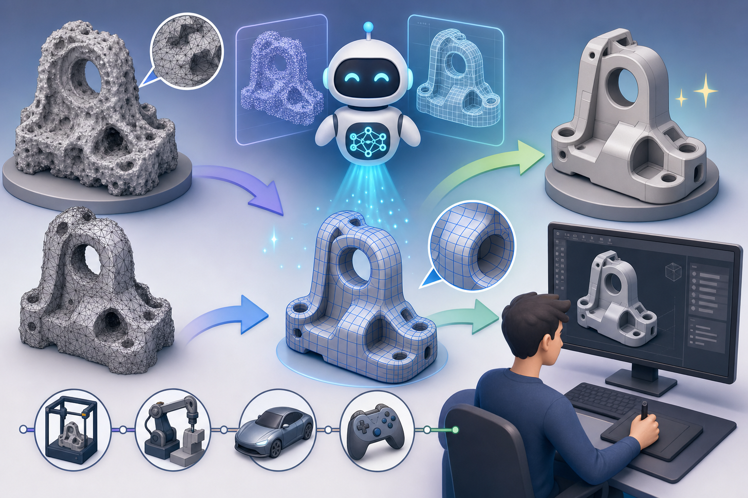
AI Retopology and Mesh Cleanup for Design Software Workflows


Mesh Quality Has Become a Strategic Design Constraint
The hidden dependency behind modern geometry workflows
Retopology and mesh cleanup have moved from specialist production tasks to central workflows in design software because design teams now consume geometry from many imperfect sources. A product model may begin as a 3D scan, a photogrammetry capture, a sculpted concept, a topology optimization result, a simulation mesh, or a legacy STL file with no original CAD history. Each source can be valuable, but each can also arrive as a dense, noisy, fragmented surface that is difficult to render, edit, print, simulate, or convert into engineering geometry. The issue is no longer simply that meshes are messy; it is that mesh quality directly determines whether downstream automation can succeed. A model with non-manifold edges may fail in slicing software. A scan with inconsistent normals may render incorrectly. A generative design output may preserve structural logic but be too irregular for manufacturing preparation. In this environment, cleanup is not cosmetic maintenance. It is the translation layer that allows creative design, engineering validation, and manufacturing execution to work from the same geometric foundation.
Where Modern Mesh Problems Usually Originate
High-density geometry is useful, but rarely production-ready
Most problematic meshes are not defective because the design process failed; they are problematic because the source workflow optimized for capture, exploration, or calculation rather than production readiness. A 3D scanner records surface samples, not design intent. Photogrammetry reconstructs appearance and approximate form, not clean edge flow. Sculpting tools favor expressive detail and organic freedom, often producing topology that is visually rich but technically inefficient. Generative design and topology optimization produce forms driven by loads, constraints, and material removal, but the resulting mesh often contains jagged transitions, thin ribs, small islands, and dense triangle clusters. Simulation meshes may be ideal for numerical analysis but unsuitable for visualization or manufacturing because element quality is governed by solver requirements rather than visual or fabrication requirements. Legacy STL assets present a different problem: they often preserve only tessellated output, stripping away parametric features, sketches, constraints, and NURBS surfaces that would normally support controlled editing.
- 3D scans often contain noise, holes, partial captures, and overlapping surfaces.
- Photogrammetry assets commonly include uneven density, texture-dependent artifacts, and incomplete underside regions.
- Sculpted models may have beautiful forms but chaotic edge flow and excessive local detail.
- Simulation and optimization meshes may carry computational meaning without manufacturable surface continuity.
- Legacy STL files may be watertight enough to view but too fragile for reliable modification.
The Technical Defects That Break Downstream Use
Small topology errors can create large workflow failures
Mesh cleanup matters because many downstream tools are far less forgiving than viewport display. A digital model can look acceptable on screen while containing defects that break slicing, UV unwrapping, simulation, or CAD reconstruction. Non-manifold edges are among the most common failures because they create ambiguous geometry: the software cannot determine which side is inside, which side is outside, or whether the object represents a valid solid. Holes and gaps prevent watertightness, while self-intersections create overlapping volumes that confuse physical interpretation. Degenerate triangles and sliver polygons can destabilize meshing algorithms, produce shading artifacts, and create unpredictable normals. Excessive polygon counts slow collaboration, increase file sizes, and make interactive visualization difficult, especially for browser-based configurators or XR applications. Thin walls may pass visual review but fail fabrication because they violate process constraints. Floating geometry, enclosed voids, and internal artifacts can also cause slicers to generate unexpected toolpaths, supports, or trapped material regions.
- Non-manifold edges make solid interpretation unreliable.
- Self-intersections create ambiguous overlapping volumes.
- Inconsistent normals cause rendering, analysis, and export errors.
- Poor edge flow makes deformation, subdivision, and UV layout difficult.
- Thin walls and floating fragments can make additive manufacturing unpredictable.
Why Retopology Is More Than Polygon Reduction
Clean topology preserves meaning, not just shape
It is tempting to describe retopology as a way to reduce polygon count, but that definition is too narrow for advanced design workflows. Simple decimation removes triangles according to mathematical rules, usually attempting to maintain a visible approximation of the original surface while reducing density. True retopology does something more sophisticated: it reorganizes the mesh so that the surface has usable structure. For visualization, that structure may mean clean silhouettes, stable shading, efficient UV islands, and topology that supports subdivision. For animation, it may mean edge loops that follow deformation paths around joints, handles, folds, or flexible features. For reverse engineering, it may mean recognizing planar faces, cylindrical holes, fillets, symmetry, and repeated features that can be reconstructed as CAD-like surfaces. For additive manufacturing, it may mean creating a watertight, manifold, physically valid shell with wall thicknesses that match process limits. In each situation, the best topology is defined by the final use case, not by polygon count alone.
How AI Changes Cleanup from Manual Repair to Intelligent Reconstruction
From surface editing to shape interpretation
Traditional retopology has depended heavily on expert manual labor. A skilled artist, designer, or engineer examines the dense mesh, identifies important forms, draws new edge loops over the surface, fills holes, rebuilds features, reduces density, and checks for geometric defects. This process can produce excellent results, but it is time-consuming and difficult to scale across large scan libraries, product catalogs, generative outputs, or architectural environments. AI-driven systems change the workflow by moving from manual repair toward automated interpretation. Instead of treating all triangles as equal, an intelligent system can infer which regions correspond to sharp edges, smooth organic transitions, mounting features, openings, handles, panels, fillets, or repeated details. This matters because mesh cleanup is fundamentally a decision-making process. The software must decide what to preserve, what to simplify, what to reconstruct, and what to remove. AI retopology becomes powerful when it recognizes design intent beneath geometric noise, rather than merely applying uniform simplification to every surface region.
- Manual retopology asks users to redraw usable structure over unusable structure.
- Automated cleanup removes obvious defects but may miss functional intent.
- AI-assisted reconstruction can classify features before deciding how to modify the mesh.
- Context-aware systems can optimize differently for rendering, printing, CAD conversion, or simulation.
Feature Detection as the Core of Intelligent Mesh Processing
Preserving edges, openings, symmetry, and functional detail
One of the most important AI-enabled capabilities is automatic feature detection. In conventional cleanup, the software may see a dense scan as a continuous field of triangles, but design users see structured elements: a planar face, a circular hole, a chamfer, a raised logo, a vent pattern, a mounting boss, or a filleted transition. Feature detection attempts to bridge this gap by identifying meaningful regions and preserving them during cleanup. For scanned industrial parts, this may involve detecting cylindrical holes and planar surfaces even when the scan contains noise or missing patches. For consumer product visualization, it may involve preserving crisp parting lines, hard edges, button gaps, speaker perforations, and brand-critical silhouettes while reducing detail on broad, flat areas. For architectural geometry, it may involve recognizing openings, façade panels, repetitive modules, and structural edges. This capability is central because topology decisions must protect high-value features while simplifying low-value regions. Without feature detection, cleanup can easily smooth away the very details that define function, assembly, style, or usability.
Semantic Segmentation Gives Meshes Logical Structure
Dividing geometry into meaningful regions
Semantic mesh segmentation takes feature detection further by dividing a mesh into logical regions that correspond to how humans understand the object. A scanned appliance might be segmented into panels, handles, vents, feet, buttons, and openings. A vehicle interior component might be divided into soft-touch surfaces, seams, mounting zones, clips, and visible trim. An architectural scan might be separated into walls, floors, ceilings, columns, windows, and service elements. This is valuable because different regions often require different cleanup rules. A handle may need curvature continuity and structural thickness. A panel may need smooth normals and clean UV layout. A mounting region may require accurate hole position and preserved mechanical alignment. A decorative texture may be visually important yet unnecessary for CAD reconstruction. By assigning semantic meaning, AI systems can apply adaptive cleanup, surface reconstruction, and polygon reduction with greater precision. Semantic segmentation turns an unstructured triangle cloud into a design-aware model, making it much easier to prepare geometry for visualization, engineering, manufacturing, or reuse.
- Visible exterior regions may prioritize shading quality and visual fidelity.
- Mechanical interfaces may prioritize dimensional accuracy and feature preservation.
- Hidden internal regions may be simplified or removed to reduce file size.
- Flexible or animated regions may require topology that follows deformation paths.
- Manufacturing-critical regions may require wall thickness validation and watertightness.
Adaptive Polygon Reduction Replaces Uniform Decimation
Simplification should follow importance, not triangle count
Uniform decimation is useful but blunt. It reduces mesh density according to broad geometric thresholds, often treating decorative details, mechanical interfaces, smooth fields, and silhouette-defining edges as variations of the same problem. Adaptive polygon reduction is more intelligent because it allocates polygon budget according to perceptual and functional importance. A broad flat underside may be reduced aggressively with little visual impact. A curved product silhouette may require more geometry to avoid faceting in real-time rendering. A fillet around a mounting boss may need enough resolution to preserve physical accuracy. A visible embossed logo might require more detail for marketing visualization, while the same logo could be removed before simulation or simplified before printing. AI can improve this process by learning which geometric features tend to matter in particular workflows. The output is not merely smaller; it is more appropriate. For web visualization, this means faster loading and stable frame rates. For XR, it means lower latency. For design collaboration, it means lighter files without destroying the geometry people actually need to evaluate.
Intelligent Hole Filling and Surface Reconstruction
Repairing missing geometry without inventing the wrong shape
Hole filling can appear simple, but advanced repair requires careful interpretation. A small triangular gap on a smooth scan may be filled by interpolating surrounding curvature. A missing patch on a planar surface should remain planar. A damaged edge near a cylindrical hole should preserve the circular boundary. A large missing region on a mechanical part may require symmetry detection, repeated feature inference, or reference-based reconstruction. Poor hole filling creates surfaces that are technically closed but geometrically misleading, which can compromise reverse engineering, simulation, or fabrication. AI-based reconstruction can analyze surrounding topology, curvature, normal direction, edge continuity, and repeated patterns to infer plausible surfaces. In product design workflows, this helps transform incomplete scan data into smoother, more usable digital models. In additive manufacturing preparation, it helps ensure that gaps become valid solids rather than fragile patches. In visualization, it prevents distracting holes and shading discontinuities. The goal is not simply to close the mesh; the goal is to reconstruct geometry in a way that remains consistent with the object’s functional and visual logic.
Quad Remeshing and Edge Flow for Visualization and Animation
Why triangle meshes are not always the best downstream format
Many captured or generated meshes are triangle-heavy because triangles are flexible and easy for algorithms to produce. However, triangle meshes are not always ideal for editing, subdivision, animation, or high-quality shading. Quad remeshing attempts to rebuild surfaces with four-sided polygons that follow the dominant flow of the form. This is especially useful when a model must be subdivided, textured, animated, or edited in a digital content creation environment. Clean quad topology can guide UV seams more predictably, reduce shading artifacts, and support smooth deformation. For product visualization, quad remeshing helps convert dense engineering or scan data into assets suitable for real-time rendering while retaining crisp silhouettes and controlled highlights. For organic shapes, it can align loops with natural curvature. For hard-surface models, it can preserve edges around panels, holes, and fillets. AI can assist by detecting where edge loops should flow, where poles should be placed, and which features should remain sharp. This turns retopology into a more automated, design-sensitive process rather than a purely manual rebuilding exercise.
Printability Repair Requires Physical Awareness
A beautiful mesh can still be impossible to manufacture
Additive manufacturing exposes the difference between visual surfaces and physically valid solids. A mesh that looks excellent in a renderer may fail in a slicer because it has open boundaries, inverted normals, intersecting shells, paper-thin walls, internal duplicate surfaces, or enclosed voids. Printability repair requires the software to understand not only topology but also process constraints. Powder bed fusion, material extrusion, vat photopolymerization, binder jetting, and metal additive processes each impose different requirements for minimum wall thickness, drainage, support, overhang, and enclosed volume. AI-driven cleanup can help by detecting areas likely to break during printing, regions too thin to fabricate, unsupported features, or internal artifacts that confuse slice generation. It can also identify whether a repair should thicken a wall, close a gap, remove a floating shell, merge intersecting geometry, or flag a feature for user review. Watertightness is necessary but not sufficient; print-ready geometry must also be coherent, process-aware, and structurally plausible enough to survive fabrication and post-processing.
- Watertight meshes define a clear inside and outside.
- Manifold topology prevents ambiguous slicing behavior.
- Minimum wall checks reduce fragile or unprintable regions.
- Internal artifact removal prevents unintended trapped material or toolpaths.
- Support and overhang awareness improves manufacturing planning.
Product Visualization Benefits from Cleaner, Lighter Geometry
Real-time experiences depend on disciplined mesh preparation
Product visualization workflows increasingly require geometry to move beyond offline rendering into real-time experiences, including web configurators, digital showrooms, augmented reality, virtual reality, and interactive sales tools. These environments are highly sensitive to file size, polygon count, texture layout, material organization, and draw-call efficiency. CAD models are often too heavy, while scans may contain unnecessary micro-detail and inconsistent topology. AI-driven retopology can create lightweight assets that preserve visual identity while removing hidden, redundant, or low-value geometry. For example, the crisp outline of a product, the curvature of a reflective housing, and the detail around user-facing controls may be preserved, while unseen internal parts and oversampled flat surfaces can be simplified. Cleanup also improves UV unwrapping because organized topology supports more predictable seams and reduced distortion. Better UVs lead to cleaner material assignment, sharper texture baking, and more controllable rendering. In this context, mesh cleanup becomes a performance strategy, allowing design teams to deliver interactive visual quality without overwhelming browsers, mobile devices, or XR headsets.
Reverse Engineering Depends on Recognizable Surface Logic
From scan data to editable design models
Reverse engineering is one of the areas where AI-driven mesh cleanup can produce significant workflow gains because scanned data rarely arrives as editable design intent. A scan may represent the outer form of a part, but it does not automatically reveal which surfaces are planes, cylinders, cones, freeform patches, fillets, slots, or repeated features. To rebuild the part in CAD, engineers need stable references and recognizable geometry. AI can assist by segmenting the mesh into surface types, detecting symmetry, identifying hole patterns, estimating axes, smoothing noise, and preparing regions for NURBS fitting or parametric reconstruction. This does not remove the need for engineering judgment, especially when tolerances, wear, damage, or deformation must be considered, but it shortens the path from raw capture to usable model. A worn physical part may contain dents or rounded edges that should not be preserved as design features. Intelligent cleanup can help separate manufacturing intent from physical degradation, giving users a cleaner base for rebuilding obsolete, damaged, customized, or undocumented components.
Generative Design Outputs Need Manufacturing Translation
Performance geometry is not automatically production geometry
Generative design and topology optimization create some of the most compelling reasons for intelligent retopology. These workflows often generate intricate structures based on loads, constraints, material distribution, and performance targets. The resulting forms can be highly efficient, but they are frequently rough, faceted, irregular, or difficult to manufacture without further interpretation. Stress-driven branches may need smoothing. Thin members may need thickening or redesign. Transition zones may require fillets to reduce stress concentration or improve printability. Surfaces may need to be converted from jagged mesh output into clean subdivision or CAD-compatible geometry. AI-driven retopology can help retain the performance logic of the optimized structure while making it more suitable for downstream fabrication, inspection, and visualization. The objective is not to erase the algorithmic character of the design, but to convert it into a controlled model that can be validated, communicated, and manufactured. This is especially important when teams want to move quickly from simulation-driven concepts to additive manufacturing, casting preparation, or hybrid CAD refinement.
- Optimization meshes may need smoothing while preserving load paths.
- Unsupported branches may need modification for additive manufacturing.
- High-density simulation output may need surface reconstruction for CAD reuse.
- Irregular transitions may need filleting, thickening, or topology correction.
- Performance intent must be preserved during simplification and repair.
Simulation Accuracy Is Also a Mesh Quality Problem
Bad cleanup can distort engineering conclusions
Mesh processing affects simulation in two different ways. First, simulation often requires its own high-quality volumetric or surface mesh, with element size, aspect ratio, and refinement zones appropriate to the physics being solved. Second, the geometry being simulated must accurately represent the design features that influence behavior. If cleanup removes small but structurally important ribs, rounds off contact regions, closes ventilation openings, or distorts wall thickness, the simulation may produce misleading conclusions. AI-assisted cleanup can help identify which features are likely functional and should be preserved before analysis geometry is generated. It can also simplify non-critical visual detail that would make the solver unnecessarily expensive. This distinction is crucial in engineering computation because the best simulation model is rarely the most detailed model. It is the model that retains relevant physical behavior with controlled complexity. Advanced design software is moving toward workflows where mesh simplification, defeaturing, and analysis preparation are tied to engineering context rather than performed as isolated manual steps.
AI Retopology as a Translation Layer Between Workflows
The same source mesh may require different final forms
The most important way to understand AI retopology is not as a single command, but as a translation layer between source geometry and downstream requirements. The same scanned object might need several different outputs. For marketing visualization, it may need clean shaders, optimized textures, low polygon count, and preserved exterior appearance. For 3D printing, it may need watertight topology, validated wall thickness, supported features, and removal of internal artifacts. For CAD reconstruction, it may need segmented surfaces, feature recognition, symmetry analysis, and curve extraction. For simulation, it may need simplification that preserves physical behavior while eliminating visual clutter. AI becomes valuable when it can adapt cleanup strategies to the intended destination. A visual mesh needs clean silhouettes and efficient rendering. A print mesh needs manifold, physically valid geometry. A reverse-engineered model needs recognizable surfaces and constraints. Treating these as the same problem leads to poor results. Treating them as context-specific transformations makes mesh processing far more useful in professional design pipelines.
Practical Workflow Recommendations for Design Teams
Building mesh intelligence into daily production
Teams adopting AI-driven retopology should begin by defining output requirements before choosing cleanup settings. A common mistake is to repair a mesh generically and only later discover that the result is unsuitable for printing, rendering, CAD conversion, or simulation. The better approach is to classify the asset by destination and then apply rules that match the intended use. For visualization, establish polygon budgets, texture resolution targets, naming conventions, and material grouping standards. For additive manufacturing, define minimum wall thickness, watertightness checks, allowable tolerances, and process-specific constraints. For reverse engineering, decide which features must become editable CAD geometry and which surface imperfections should be ignored. For generative design outputs, identify which regions carry structural performance and which regions can be smoothed or simplified. AI tools can accelerate this process, but they should be guided by clear criteria. The goal is not fully automatic geometry repair in isolation; the goal is repeatable, explainable mesh preparation that supports collaboration across design, engineering, visualization, and manufacturing teams.
- Define the final workflow before beginning cleanup.
- Preserve functional features differently from decorative details.
- Validate watertightness, normals, and manifold topology before fabrication.
- Use adaptive reduction rather than uniform decimation whenever possible.
- Keep original source meshes archived for traceability and comparison.
- Review AI-generated repairs where tolerances, fit, or safety are important.
The Future of Context-Aware Mesh Cleanup
From automated repair to interactive topology assistants
The future of mesh processing will likely be defined by context-aware automation. Instead of asking users to manually choose dozens of abstract parameters, design software will increasingly ask what the model is for. If the answer is browser-based visualization, the system may optimize for polygon budget, texture baking, material consolidation, and level-of-detail generation. If the answer is metal additive manufacturing, it may evaluate support requirements, wall thickness, enclosed voids, and thermal risk indicators. If the answer is CAD reconstruction, it may segment surfaces, detect primitives, suggest sketches, and rebuild editable features. If the answer is simulation, it may preserve load paths, contact areas, and boundary-condition regions while removing irrelevant decorative detail. AI assistants may also explain topology problems interactively, highlighting why an edge is non-manifold, why a shell is ambiguous, why a hole fill is risky, or why a simplified result may compromise visual accuracy. This explanatory layer is important because professional users need confidence, not black-box geometry changes. The next generation of mesh tools will optimize, repair, and teach at the same time.
Cleaner Meshes Will Enable More Automated Design Pipelines
Mesh intelligence reduces friction from scan to model and model to production
AI-driven retopology and mesh cleanup are becoming foundational technologies because modern design pipelines increasingly depend on scanned, generated, simulated, and procedurally created geometry. Manual cleanup cannot scale indefinitely, especially as teams work with larger datasets, faster iteration cycles, and more output channels. The real promise of AI is not only faster repair; it is smarter interpretation. Advanced systems will ask which geometry matters, which details can be simplified, which features are functional, which surfaces must remain visually accurate, and which errors will break printing, rendering, conversion, or simulation. As this intelligence becomes embedded inside design software, teams will move more fluidly from scan to editable model, from generative output to manufacturable part, and from CAD data to immersive visualization. Better topology will also improve collaboration because lighter, cleaner, more reliable files are easier to review, share, version, and automate. In the long term, mesh intelligence will become one of the quiet foundations of digital design continuity, connecting creative exploration, engineering computation, product visualization, and manufacturing execution with far less friction.
Also in Design News