Your Cart is Empty


Introduction
Organizations are converging on aggressive weight, cost, and sustainability targets while compressing design timelines. In that context, topology optimization and lightweighting—especially when aligned with AM-ready strategies—have become foundational, not experimental.
Selection criteria for this guide
- Native integration with SOLIDWORKS for frictionless handoff and in-context iteration
- Solver sophistication across linear/nonlinear, modal, thermal, and contact behaviors
- Manufacturability controls (symmetry, pull/extrusion, overhang, thickness, de-mold)
- Lattice and implicit modeling capabilities where additive provides maximum value
- Workflow speed from setup through retopology and detailing
- Data handoff back to editable CAD, minimizing dependence on raw meshes
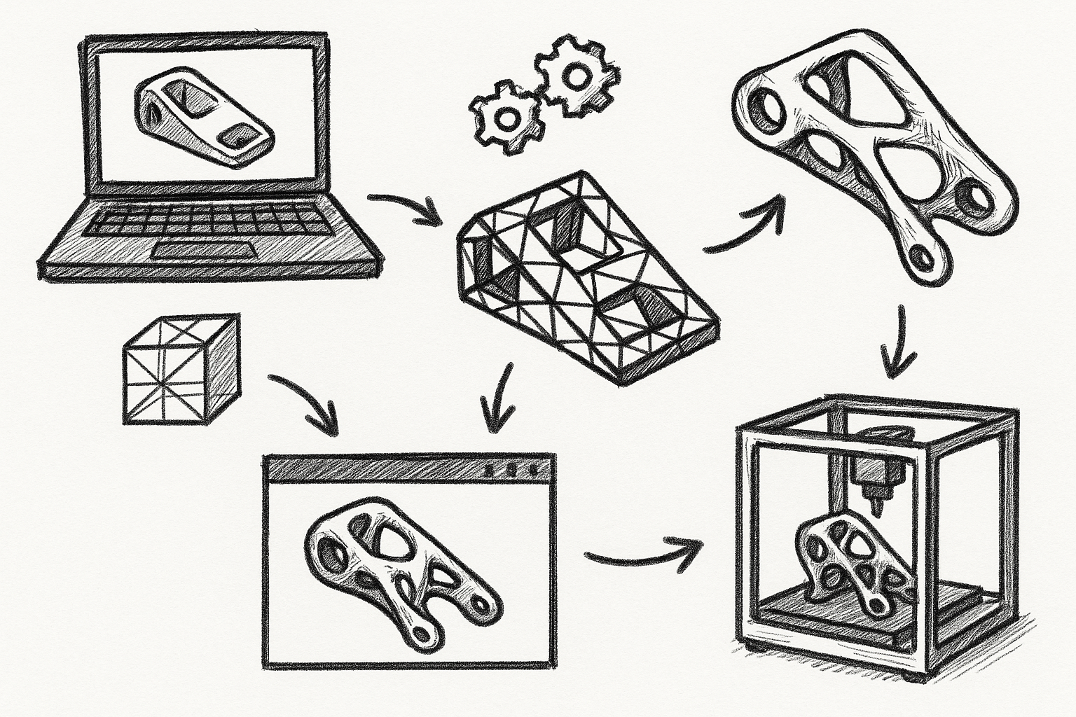
SOLIDWORKS Simulation Topology Study (native add-in)
What it is
SOLIDWORKS Simulation Professional/Premium includes a built-in topology optimization study that runs directly inside the SOLIDWORKS interface. It provides in-context generative exploration without leaving the CAD environment, making it approachable for design engineers who already rely on SOLIDWORKS for day-to-day work.
Standout capabilities
- Objectives to minimize mass or compliance with constraints on stiffness/displacement, frequency, and stress
- Manufacturing restrictions including symmetry, de-mold/pull direction, and extrusion-friendly shapes
- Multi-load case support, preserved regions, excluded regions, and design constraints
- Smooth mesh result creation and mesh-to-BREP workflows via Mesh Features, Surfacing, and hybrid modeling
- Fast “what-if” loops using configurations and study duplication
Best for
Quick, in-context generative concepts on prismatic or mechanical parts that will ultimately be re-built as editable parametric features. It fits teams that want to learn fast inside CAD and are comfortable performing surfacing or feature reconstruction after optimization.
Typical workflow
- Define loads and boundary conditions; protect interfaces (mounting faces, bores, datum bosses) as preserved regions
- Set objective and constraints; apply manufacturing controls (symmetry, pull, or extrusion) aligned with intended process
- Solve and interpret the element density/isosurface result
- Create a smooth mesh body; export or convert using Mesh Features, surfaces, and solid features
- Reparameterize to design intent with dimensions, relations, and design tables
Guidance and pitfalls
- Begin with coarse studies to map load paths, then refine; early overfitting wastes time and risks misleading geometry
- When machining is the target, enforce draw or extrusion controls from the start to avoid unmanufacturable cavities
- Plan time for retopology; do not commit the raw mesh to production unless the downstream process accepts it
- Use frequency constraints to protect against low first modes on brackets or arms
Licensing and compatibility
Requires SOLIDWORKS Simulation Professional or Premium. Versions 2018 and newer offer the most mature mesh/BREP conversion tools.
Validation checkpoints
- Re-verify the re-modeled geometry with standard FEA, not just the topology result
- Check modal targets and critical displacements on all load cases, including combinations/envelopes
- Evaluate stress hot spots from sharp transitions introduced during reparametrization
3DEXPERIENCE Works Generative Design (SIMULIA) via SOLIDWORKS Connector
What it is
Through the 3DEXPERIENCE platform, roles like Generative Design Engineer and Structural Professional Engineer provide cloud/offloaded SIMULIA capabilities accessible from SOLIDWORKS. You publish models via the connector, define design spaces, and run Abaqus-grade solvers at scale with versioned data and collaboration.
Standout capabilities
- High-fidelity nonlinear, contact, and thermal-mechanical analyses with implicit time integration options
- Robust manufacturability constraints including symmetry, pull/extrusion, overhang controls, and minimum thicknesses
- Design space exploration generating multiple candidates with comparable metrics
- Concurrency and cloud scaling for batch studies and parametric sweeps
- Traceability, approvals, and lifecycle management baked into the platform
Best for
Enterprise teams optimizing under complex physics who need governance, auditability, and collaboration. It excels when the design envelope must balance multi-mode performance targets with documented controls for manufacturability and quality.
Typical workflow
- Publish the SOLIDWORKS model to 3DEXPERIENCE with preserved/forbidden regions and metadata
- Define the design space, loads/constraints, materials, and manufacturing rules
- Run cloud studies; review candidate set side-by-side by mass, compliance, criteria pass/fail
- Downselect; export a smoothed body or iso-surface and bring it back into SOLIDWORKS for detailing
- Iterate with change management and markups; lock configuration upon signoff
Guidance and pitfalls
- Use templates to codify recurring design rules across part families (keeps, offsets, bolt zone clearances)
- Pre-clean CAD to eliminate sliver faces and tiny gaps; better geometry reduces solver overhead and convergence risk
- Budget cloud credits and queue time, especially when running nonlinear and contact-heavy scenarios
- Leverage platform dashboards to compare candidates by cost/mass/performance for objective downselects
Licensing and compatibility
Requires the relevant 3DEXPERIENCE Works roles (e.g., Generative Design Engineer, Structural Professional Engineer) and the SOLIDWORKS connector for data synchronization.
Validation checkpoints
- Spot-check leading candidates against in-CAD Simulation for consistency on linear cases
- Document manufacturability checks: overhangs, minimum feature sizes, and orientations suitable for the target process
- Confirm material models (plasticity/creep/fatigue) align with supplier data and expected service conditions
3DXpert for SOLIDWORKS (3D Systems) for AM lattices and lightweighting
What it is
3DXpert for SOLIDWORKS is an add-in focused on additive manufacturing preparation and lattice/TPMS lightweighting. It brings advanced lattice generation, build simulation, orientation optimization, supports, and slicing directly into the SOLIDWORKS workflow—particularly well-suited for metal AM but effective for polymers too.
Standout capabilities
- Advanced lattice libraries: strut-based and TPMS/gyroid variants with variable density and graded parameters
- Shelling and infill strategies tailored to stress distribution and thermal paths
- Automatic support generation with fine control over anchors, perforations, and removal strategies
- Distortion compensation and build simulation for residual stress and shrinkage prediction
- Direct toolpaths and slicing for many printers, reducing post-export handoffs and translation errors
Best for
AM-first designs where lattice and implicit structures are the primary mass-reduction mechanisms and where build readiness is a deliverable, not an afterthought. Ideal when design and manufacturing teams operate as a single loop from concept to machine.
Typical workflow
- Set mass reduction targets and allowable stiffness or compliance envelopes
- Convert solid sections to shells; populate with lattice or TPMS regions with graded density
- Optimize part orientation to minimize supports and thermal risk; auto-generate supports
- Simulate build to evaluate distortion, recoater interference, and hot spots
- Apply distortion compensation; export slice or printer-ready files to the specific machine
Guidance and pitfalls
- Respect minimum strut thickness and cell size for the chosen machine/material; over-aggressive grading leads to nonconformance
- Use graded lattices where stress gradients justify complexity; uniform lattices simplify inspection and NDE
- Include witness coupons and parameter blocks for qualification and CT correlation on critical builds
- Plan post-processing early (powder removal, heat treatment, HIP) to avoid inaccessible cavities
Licensing and compatibility
Provided as 3DXpert for SOLIDWORKS with tiered capabilities; higher tiers unlock advanced lattice controls and build simulation options.
Validation checkpoints
- Correlate lattice FEM or homogenized properties with printed test coupons for the specific parameter set
- Verify distortion-compensated results against GD&T after stress relief and finishing
- Confirm support removal strategy and surface roughness targets on load-bearing regions
Ansys Workbench Associative Interface for SOLIDWORKS + Ansys Topology Optimization
What it is
The Ansys Workbench associative interface links SOLIDWORKS geometry to Ansys Mechanical, enabling topology optimization and advanced multi-physics analysis. Changes can be synchronized back, preserving design intent while giving access to high-end solvers and the Ansys Additive Suite for downstream workflow continuity.
Standout capabilities
- Topology optimization driven by structural, thermal, and modal responses, including frequency and multi-load constraints
- Manufacturing controls: draw/extrude directions, symmetry, and overhang management
- Post-optimization smoothing, iso-surface extraction, and rapid re-analysis in a single environment
- Integration with Ansys Additive Suite for process simulation, support optimization, and lattice design
- Robust parameter linking to reflect thickness or feature changes back in SOLIDWORKS
Best for
High-fidelity optimization where coupling to thermal or dynamic requirements is mandatory and where formal verification and validation are part of the release process. Suited to industries where enterprise verification and traceability are non-negotiable.
Typical workflow
- Send SOLIDWORKS geometry to Workbench via the associative interface
- Define design space, preserved zones, loads, boundary conditions, and material models (including temperature dependence)
- Run topology with response constraints; extract an iso-surface and smooth
- Reimport to SOLIDWORKS for retopology; drive dimensions with parameters linked to Ansys where practical
- Re-verify and hand off to additive or machining workflows with documented assumptions
Guidance and pitfalls
- Apply response constraints early (e.g., modal gaps, thermal gradients) to prevent converging on infeasible topologies
- Keep design spaces simple; convoluted envelopes slow convergence and can trap non-physical artifacts
- Use parameter linking to accelerate loops between thickness tuning and performance targets
- When coupling thermal and structural, ensure consistent boundary conditions across physics domains
Licensing and compatibility
Requires Ansys Mechanical with topology optimization features and the Workbench associative interface for SOLIDWORKS. Ansys Additive Suite is optional but synergistic for AM paths.
Validation checkpoints
- Back-to-back correlation of Ansys results with SOLIDWORKS Simulation on comparable linear cases
- Document sensitivity to load-case weighting and ensure modal spacing meets system-level requirements
- Where possible, correlate thermal-structural predictions with instrumented prototypes
Altair SimSolid Add-in for SOLIDWORKS (analysis-driven lightweighting accelerator)
What it is
Altair SimSolid is a meshless solver connected to SOLIDWORKS that excels at ultra-fast structural analysis of complex parts and assemblies. While not a topology optimizer, its speed makes it a powerful guide for manual and parametric lightweighting via rapid “analyze–trim–verify” loops.
Standout capabilities
- Solves large assemblies without meshing; handles extensive contact and bolted connections efficiently
- Excellent for screening material removal ideas, rib patterns, and wall thickness changes
- Rapid convergence facilitates exploring load-case envelopes instead of single-scenario tuning
- Direct SOLIDWORKS add-in for quick geometry transfer and update
Best for
Early-phase design where speed of learning dominates and teams need to prune design options quickly. It is especially useful on welded frames, castings with many fillets, and multi-part systems with complicated joint behavior.
Typical workflow
- Push the baseline geometry from SOLIDWORKS and solve to establish margins
- Remove pockets, add holes, thin walls, or alter rib patterns parametrically in SOLIDWORKS
- Re-solve in seconds; compare displacements, stress, and modal response against targets
- Iterate to converge on weight with a safety margin maintained across all load cases
Guidance and pitfalls
- Calibrate with one high-fidelity reference analysis to establish confidence bounds
- Use load-case envelopes and service factors to avoid over-thinning for a single scenario
- Track simplifications (omitted fillets, fasteners) and quantify their influence periodically
- Transition to a detailed solver once geometry stabilizes to confirm hot spots and local details
Licensing and compatibility
Requires an Altair SimSolid license; the SOLIDWORKS add-in streamlines model transfer and re-analysis through design changes.
Validation checkpoints
- Verify the final design with a detailed FEA tool (Abaqus/Ansys/SOLIDWORKS Simulation) and physical testing where risk warrants
- Confirm joint stiffness assumptions for bolted and bonded interfaces on the final configuration
Comparing approaches in practice
While each solution aims at mass reduction and performance, they differ in how they trade speed, fidelity, manufacturability, and downstream readiness:
- In-CAD topology accelerates concept shaping and preserves design context but typically requires careful retopology for production.
- Cloud generative platforms unlock candidate exploration and heavy physics while embedding governance—a fit for distributed teams and regulated workflows.
- AM-first lattice tools maximize weight savings at the microstructure level and shorten the path to the machine, with the caveat of stricter process control and inspection planning.
- Enterprise multi-physics integrates system constraints early, preventing late-stage surprises on dynamics or thermal demands.
- Meshless screening propels learning speed in assemblies and complex parts, guiding where a full optimization study is worth the time.
Practical modeling considerations that amplify results
Independent of tool choice, certain modeling practices consistently improve outcomes and reduce rework:
- Define preserved zones with generous offsets around holes, bearing seats, sealing faces, and torque paths; then trim later if margins allow
- Normalize loads across studies and define consistent material models so you compare like-for-like when downselecting approaches
- Incorporate manufacturing rules from the first iteration so geometry doesn’t drift into impossible-to-produce forms
- Favor simple envelopes and clean topology change boundaries; the solver will exploit the freedom you allow, so constrain where assembly and service require
- Use validation loops after every major geometry change: re-run modal and critical displacement checks, then revisit fatigue implications if applicable
Conclusion
How to choose
- Need in-CAD, quick generative starts: choose SOLIDWORKS Simulation Topology Study.
- Need cloud scale and Abaqus fidelity with managed collaboration: choose 3DEXPERIENCE Works Generative Design.
- AM-first with lattices and print-readiness: choose 3DXpert for SOLIDWORKS.
- Multi-physics and enterprise verification: choose Ansys via the associative interface.
- Fast iteration to guide manual lightweighting on complex assemblies: choose Altair SimSolid.
Next steps
- Pilot two tools on the same benchmark part under identical loads and constraints
- Measure mass reduction, compliance to performance limits, retopology/detailing time, and print-readiness
- Standardize a cross-team validation checklist, including manufacturability, inspection, and data traceability
- Institutionalize templates (keeps, manufacturing constraints, load envelopes) to reuse across product families