Your Cart is Empty


Rhino 3D Tip: Professional Pipe Modeling in Rhino 3D
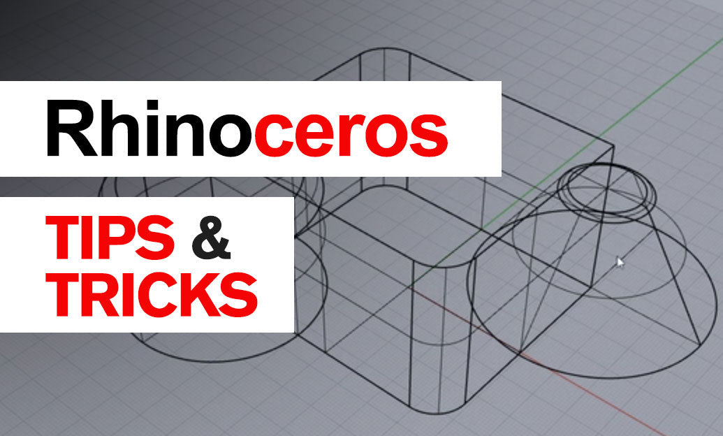

Pipe is one of Rhino’s most efficient commands for turning curves into tubular geometry. It is ideal for frames, handrails, wire forms, product details, bicycle structures, piping layouts, jewelry, and any design where a consistent or variable circular section follows a path.
Start the command by typing Pipe, select one or more rail curves, and press Enter. Rhino then asks for a radius. A single radius creates a constant-diameter pipe; additional radius values placed at locations along the rail create a variable-radius result.
-
Use clean rail curves first. The final pipe can only be as reliable as its path. Before running
Pipe, inspect the curve for unnecessary control points, tiny segments, kinks, or overlapping portions. Commands such asSimplifyCrv,Rebuild, andCheckcan help prepare cleaner rails. - Set the radius from the design intent. Remember that Pipe asks for radius, not diameter. For example, a 20 mm outside diameter tube needs a 10 mm radius. Use explicit numeric input whenever manufacturing accuracy matters.
- Add local radii strategically. After entering the first radius, click or use object snaps to place another radius location along the curve. Enter a new value to taper or swell the pipe. This is useful for ergonomic handles, organic transitions, structural members, and decorative forms.
- Choose caps deliberately. For an open rail, Rhino offers cap styles such as flat, round, or no cap. Flat caps are practical for parts that will be joined to planar faces; round caps can give a finished appearance; no caps are useful when the pipe will be trimmed, joined, or used as a surface component later.
- Watch tight bends. If a pipe radius is too large for a tight curve bend, the resulting surface may self-intersect or fail. Reduce the pipe radius, increase the rail’s bend radius, or break the design into separate features. Always inspect tight corners in a shaded display mode.
For a reliable workflow, create the centerline first and treat it as the controlling geometry. Keep it on a dedicated layer so that it remains available for future edits. If the pipe needs revision, modifying the original curve and rerunning Pipe is often cleaner than attempting to reshape the finished polysurface.
Closed rail curves deserve extra attention. A closed pipe has a seam where Rhino begins and ends the surface parameterization. Positioning the curve seam in an inconspicuous or low-stress area can make later operations—such as trimming, splitting, applying textures, or creating detailed surface edits—more predictable. Use CrvSeam before creating the pipe when seam location matters.
After generating the feature, verify the result rather than assuming it is production-ready:
- Run
Checkto identify invalid geometry. - Use
ShowEdgesto locate naked edges when a closed solid is expected. - Use
Whatto confirm whether the result is a surface, polysurface, or closed solid. - For fabrication, use
VolumeorMassPropertiesto validate physical properties.
If a Pipe feature must merge with another solid, create it with enough clearance around intersections, then use BooleanUnion. When booleans fail, inspect for tangent-only contact, self-intersections, or extremely small features. Splitting and rebuilding the connection with simpler, cleaner geometry is usually faster than forcing an unreliable boolean.
For Rhino tools, training, and workflow resources, explore Rhino solutions at NOVEDGE. Building pipes from well-managed curves is a small discipline that produces cleaner models, more dependable booleans, and better downstream fabrication results.
You can find all the Rhino products on the NOVEDGE web site at this page.
Also in Design News