Your Cart is Empty
Design Software History: Reverse-Engineered Parametric Reconstruction in CAD History
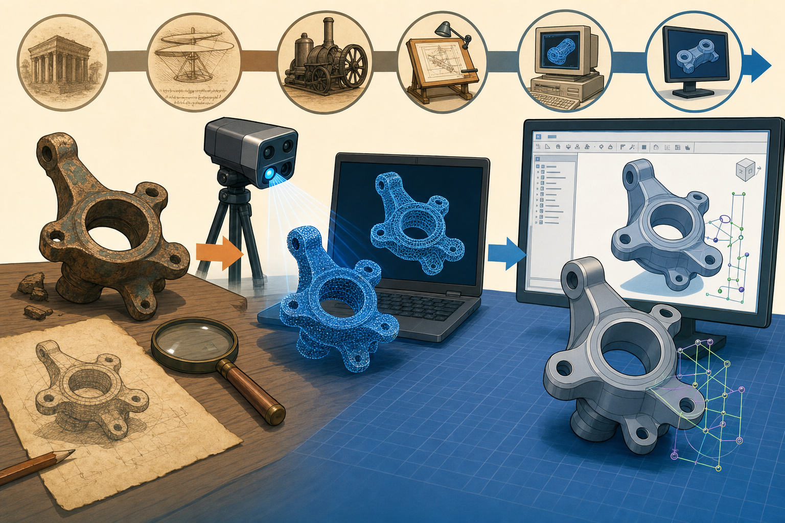


From physical evidence to editable geometry
The historical gap between the shop floor and the CAD database
Reverse engineering became important because industry repeatedly found itself holding a useful physical artifact without possessing a reliable digital definition of it. A manufacturer might have a cast aerospace bracket qualified decades earlier, a stamping die modified by toolmakers on the shop floor, a hand-built prototype refined by sanding and welding, or an automotive clay model approved by executives but not yet represented as manufacturable geometry. The problem was not simply that the part needed to be copied. The deeper problem was that modern design, simulation, tooling, inspection, procurement, and product lifecycle management increasingly depended on editable CAD data. Legacy physical objects had to re-enter a digital engineering environment that expected features, dimensions, tolerances, surfaces, mass properties, and assembly references. This is where reverse-engineered parametric reconstruction emerged as a distinct discipline. It promised to move beyond scanning an object as a visual shell and toward rebuilding the underlying design language that a CAD system such as CATIA, Pro/ENGINEER, Siemens NX, SolidWorks, or Autodesk Inventor could understand.
Why measurement alone was insufficient
Early reverse-engineering workflows were rooted in measurement rather than modeling. Coordinate Measuring Machines, commonly called CMMs, used touch probes to collect discrete points from surfaces, edges, bores, and datum features. Companies such as Brown & Sharpe, DEA, Mitutoyo, Leitz, and later Hexagon Manufacturing Intelligence helped make high-precision dimensional capture routine in factories and inspection rooms. These machines were excellent at verifying that a known part matched a drawing, but they were less natural tools for reconstructing an unknown design. A sparse set of measured points could describe that something existed at a location in space, yet it did not automatically produce a plane, cylinder, boss, rib, draft surface, or hole pattern. The engineer still had to interpret the measurements. When early laser digitizers and scanning arms entered the workflow, they captured more data faster, but the fundamental issue remained: a cloud of points was not a CAD model. It was evidence, not design intent.
The distinction between shape capture and design recovery
The most important historical distinction is that reverse engineering a shape is not the same as reconstructing how that shape was designed. A scanned bracket may look to software like millions of points or thousands of triangles. To an engineer, however, the same bracket may express a very specific set of manufacturing and functional decisions: two holes should be coaxial, a boss should be centered on a web, a flange should be planar, a fillet should relieve stress at a transition, and a mounting surface should remain parallel to a mating component. These are not merely geometric observations; they are engineering relationships. Traditional mesh reconstruction could reproduce the visible part, including dents, wear, casting variation, and machining marks. Parametric reconstruction had to decide which deviations mattered and which represented noise, damage, or production tolerance. That judgment made the field technically difficult. It also made the field historically significant, because it exposed the difference between surface resemblance and editable engineering knowledge.
Industrial pressure from multiple domains
The demand came from many industries at once. Automotive companies needed to digitize clay models and legacy body panels, then convert sculpted surfaces into Class A surfacing workflows. Aerospace organizations needed repair geometry for older aircraft, turbine components, brackets, ducting, and replacement parts where drawings were incomplete or obsolete. Tooling companies needed to recover molds and dies that had been hand-polished or repeatedly modified. Medical device firms needed patient-specific implants and anatomical reconstructions, especially as CT and MRI data became more useful for manufacturing. Consumer product designers wanted to capture ergonomic forms created by sculptors and model makers. Across these domains, the same pattern appeared: physical reality existed first, while editable digital structure came later. Major CAD vendors, including Dassault Systèmes, PTC, Siemens, and Autodesk, gradually recognized that scan-based reconstruction was not a peripheral novelty. It was becoming part of the broader digital thread connecting measurement, design, manufacturing, simulation, and inspection.
The mesh era and the rise of scan-based reconstruction
How dense scanning changed expectations
The arrival of practical 3D scanning changed reverse engineering by increasing the amount of geometric evidence available. Laser scanners, structured-light systems, photogrammetry, articulated arms with scanning heads, and industrial CT systems made it possible to capture complex shapes far more quickly than traditional point-by-point probing. A hand-held or tripod-mounted scanner could cover organic surfaces, castings, sheet-metal panels, turbine blades, and molded housings in minutes rather than hours. CT scanning added a further capability by capturing internal geometry that optical systems could not see. Vendors such as FARO, Creaform, GOM, Leica Geosystems, Nikon Metrology, and Hexagon expanded the practical reach of scanning across manufacturing, research, and quality control. Yet the output was usually not a parametric CAD feature tree. It was a point cloud or polygon mesh. That mesh could be interpreted visually, measured, rendered, or used for inspection, but it did not contain explicit engineering features. It described shape in a dense but unintelligent form.
The technical pipeline behind mesh reconstruction
The standard scan-processing pipeline became a discipline of its own. First, raw scan data needed noise filtering, because scanners captured stray reflections, occlusions, speckle effects, surface glare, and environmental artifacts. Next came registration, where multiple scans from different viewpoints were aligned into a common coordinate system, often using targets, best-fit algorithms, or iterative closest point methods. Then the point cloud was converted into a polygon mesh, usually made of triangles. Holes caused by occlusion or reflective surfaces were filled, spikes were removed, boundaries were trimmed, and mesh density was reduced where the data was unnecessarily heavy. Software then performed surface fitting, deviation analysis, and sometimes curvature evaluation. This workflow was powerful because it made scan data usable. It also created a new commercial category: software that could transform raw measurement into a cleaner digital object. However, the resulting object was still often a dumb mesh, meaning it had no feature history, no constraints, and no manufacturing logic.
- Noise filtering removed measurement artifacts and stray points.
- Registration aligned multiple scans into one coordinate frame.
- Mesh generation converted points into connected triangular facets.
- Hole filling repaired missing regions caused by occlusion or reflectivity.
- Surface fitting approximated mesh regions with analytic or free-form geometry.
- Deviation analysis compared reconstructed geometry against the original scan.
Geomagic and the commercial definition of scan-to-model workflows
One of the central names in this history is Geomagic. The company began as Raindrop Geomagic, founded in the 1990s by Ping Fu and Herbert Edelsbrunner, the latter widely known for his work in computational geometry and topological methods. Geomagic became closely associated with making scan data usable for industrial workflows, particularly through tools that helped users clean point clouds, generate meshes, fit surfaces, and perform inspection. Ping Fu’s role was especially important because Geomagic framed reverse engineering not just as a mathematical problem but as an industrial productivity problem: engineers needed software that could handle messy physical reality. The company’s products helped popularize workflows where a physical object could be scanned, reconstructed, inspected, and used downstream in design or manufacturing. When 3D Systems acquired Geomagic in 2013, it reflected a broader industry movement: additive manufacturing, scanning, inspection, and digital model reconstruction were converging into a single physical-to-digital-to-physical ecosystem.
Rapidform, PolyWorks, and inspection-driven reconstruction
Rapidform, developed by INUS Technology in South Korea and later acquired by 3D Systems, represented another important branch of the field. Rapidform became known for tools that attempted to convert scan data into CAD-friendly geometry, including feature recognition and parametric reconstruction workflows that interacted with mainstream CAD systems. Its emphasis was not just on producing smooth surfaces but on producing models that could be edited meaningfully. PolyWorks, developed by InnovMetric in Canada, became influential from a metrology and inspection perspective. PolyWorks was especially strong in dimensional analysis, scan alignment, feature extraction, and comparison between manufactured parts and nominal CAD data. This mattered because reverse engineering was often inseparable from inspection. Engineers needed to know not only what a part looked like, but how far it deviated from an idealized reconstruction or from a production requirement. Together, Geomagic, Rapidform, and PolyWorks helped define the practical vocabulary of scan-based reconstruction: point clouds, meshes, deviations, fitted primitives, inspection reports, and CAD export.
The hard limit of dumb geometry
The mesh era made reverse engineering dramatically more accessible, but it also revealed a ceiling. A triangle mesh can represent the surface of a drilled hole, yet it does not know that the hole was drilled normal to a base plane, that its diameter should be exactly 10 millimeters, or that it belongs to a four-hole rectangular pattern. A fitted NURBS patch can approximate a free-form surface, but it may not reveal whether the original designer intended a ruled surface, a swept blend, or a loft controlled by specific section curves. Meshes are excellent at recording physical evidence, including imperfections, but they are poor at encoding reasons. This distinction became more painful as CAD systems moved deeper into feature-based modeling. In Pro/ENGINEER, SolidWorks, CATIA, Siemens NX, Creo, and Inventor, engineers expected to edit sketches, suppress features, change radii, modify hole sizes, and update downstream geometry. A mesh imported as a static body could rarely participate in that workflow without substantial remodeling.
Parametric reconstruction as a response to feature-based CAD
The meaning of editable reconstruction
Reverse-engineered parametric reconstruction is the process of converting scan, point-cloud, mesh, or surface data into editable CAD features. Instead of merely wrapping a surface around measured data, the software attempts to infer the kinds of operations a designer might have used: extrudes, revolves, cuts, holes, chamfers, fillets, shell operations, patterns, reference planes, datum axes, and geometric constraints. This change aligned reverse engineering with the feature-based revolution that had transformed mechanical CAD beginning in the late 1980s. PTC’s Pro/ENGINEER, introduced under the leadership of Samuel Geisberg and Parametric Technology Corporation, made parametric, history-based solid modeling central to mechanical design. Later, SolidWorks, CATIA V5, Siemens NX, and Autodesk Inventor reinforced the expectation that a model should be editable through parameters and relationships. Reverse engineering had to catch up. It was no longer enough to deliver a clean-looking solid. The reconstructed model had to behave like a native CAD part, with features that an engineer could understand, reorder, dimension, and revise.
Why the problem resisted automation
The difficulty is that scan data is not ideal CAD data. Real parts contain manufacturing variation, wear, corrosion, casting shrinkage, sanding marks, weld distortion, machining chatter, and measurement noise. A cylinder in a scan may be slightly oval. A plane may be warped. A fillet may be partially worn away. A hole may have burrs or chamfers that obscure the boundary between features. In addition, features overlap in the final shape. A boss can be blended into a rib; a rib can be drafted for molding; a hole can cut through a filleted wall; a shell operation can affect many downstream surfaces at once. From the final geometry alone, several different feature histories may be plausible. One engineer might reconstruct a shape as an extruded base followed by cuts and fillets. Another might build it from revolved surfaces and trims. Both models may match the scan, but only one may reflect the original design logic or support future modification. This ambiguity remains central to the field.
Primitive detection and analytic geometry
One foundation of parametric reconstruction is primitive detection. Many manufactured parts are composed of mathematically recognizable surfaces: planes, cylinders, cones, spheres, tori, and ruled surfaces. Algorithms search scan data or mesh regions for these primitives by fitting ideal forms to noisy samples. The Hough transform, RANSAC-type methods, least-squares fitting, region growing, curvature analysis, and normal-vector clustering all became important techniques in this area. A drilled hole, for example, can often be reconstructed by fitting a cylindrical surface and determining its axis, diameter, and relationship to nearby planar faces. A boss may be detected as a cylindrical protrusion attached to a base surface. A chamfer may be recognized as a narrow conical or planar transition. These operations sound simple, but they are difficult when scans contain incomplete coverage and when small features blend into larger ones. Still, primitive detection gave software a path from visual geometry toward manufacturing-aware interpretation, because cylinders, planes, and cones correspond closely to real machining and molding operations.
NURBS fitting and free-form surface reconstruction
Not every part can be reduced to analytic primitives. Automotive body panels, turbine blades, ergonomic grips, medical implants, and consumer product housings often rely on free-form surfaces. For these shapes, Non-Uniform Rational B-Splines, or NURBS, became essential. NURBS had already been central to CAD surfacing through systems such as CATIA, ICEM Surf, Alias, and Unigraphics. In reverse engineering, NURBS fitting allowed software to approximate scan data with smooth mathematical surfaces that could be trimmed, joined, analyzed, and exported to CAD. Least-squares surface fitting, curvature-continuity evaluation, knot placement, patch layout, and boundary construction all mattered. The challenge was not merely making a surface pass near the points. The surface had to be fair, manufacturable, and compatible with downstream modeling. A dense patch network could match a scan closely but produce an ugly, fragile CAD model. A simpler patch layout might deviate slightly more from the scan but better reflect design intent. This tradeoff between accuracy and editability became a defining issue in reverse-engineered surfacing.
Segmentation, patterns, and constraints
Segmentation is the process of dividing a mesh or point cloud into meaningful regions before reconstructing features. A successful reconstruction system must decide where one feature ends and another begins. Curvature changes, sharp edges, normal discontinuities, color data, scan density, and fitted primitives can all help. Once regions are identified, higher-level relationships can be inferred. Planes may be parallel or perpendicular. Cylinders may be coaxial. Holes may form a linear, circular, or rectangular pattern. Faces may be symmetric across a mid-plane. Repeated ribs may share spacing and thickness. These relationships are crucial because they convert geometry into constraints. In a parametric CAD model, a hole pattern should usually be editable as a pattern rather than as four unrelated cylinders. A symmetric bracket should be controlled by a center plane rather than by independent left and right surfaces. The most valuable systems therefore attempted to detect not only shapes but also relationships between shapes, because constraints are the hidden architecture of engineering design.
- Planes could become sketch planes, datum faces, or mating surfaces.
- Cylinders could become holes, bosses, pins, or revolved cuts.
- Tori and blends could become fillets with editable radii.
- Repeated features could become rectangular, circular, or curve-driven patterns.
- Symmetry could become a reference plane controlling mirrored geometry.
- Distances, angles, and concentricity could become parametric constraints.
Integration with mainstream CAD systems
Why add-ins and CAD-native workflows mattered
Parametric reconstruction became far more valuable when it could feed directly into the CAD systems engineers already used. Exporting an STL file or even a neutral surface model was not enough if the design team worked inside SolidWorks, CATIA, Siemens NX, Creo, or Autodesk Inventor. As a result, reverse-engineering companies built add-ins, plug-ins, and direct workflows intended to create native features or at least CAD-editable entities. Rapidform’s design-oriented tools, Geomagic’s scan-to-CAD products, and specialized translators attempted to bridge the gap between scan processing and feature-based modeling. The goal was to reduce the manual burden of tracing sketches over mesh sections, fitting cylinders by hand, and rebuilding features one at a time. CAD integration also mattered organizationally. Engineers wanted reconstructed models to join assemblies, drive drawings, support finite element simulation, generate toolpaths, and enter PLM systems such as Dassault’s ENOVIA, Siemens Teamcenter, or PTC Windchill. A static scan model could rarely do that cleanly.
The feature tree as historical reconstruction
A reconstructed feature tree is more than a convenience; it is an argument about how a part should be understood. When software creates an extrude, then a cut, then a fillet, then a hole pattern, it is imposing a sequence of design operations onto a physical artifact. That sequence may or may not match the original designer’s process, but it gives the modern engineer a workable model. This is why reverse-engineered parametric reconstruction sits at a fascinating point in CAD history. Feature-based CAD systems taught engineers that geometry should have memory: sketches, dimensions, constraints, and dependencies. Reverse engineering starts with an object that has no accessible memory and tries to rebuild one. The resulting model is partly measured fact and partly interpretive reconstruction. This is especially clear when deciding whether to preserve measured irregularity or restore ideal design form. A worn mold surface may be intentionally repaired to nominal smoothness. A cast pocket may be reconstructed as a planar-bottomed feature even if the scan shows slight waviness.
Solid modeling kernels and the importance of clean topology
Behind these workflows are solid modeling kernels and boundary representation technology. Parasolid, associated with Siemens and used by SolidWorks, NX, Solid Edge, and many other systems, and ACIS, originally developed by Spatial Technology and used in many engineering applications, rely on precise topological and geometric definitions. A watertight mesh does not automatically translate into a valid boundary representation solid. For a CAD system to perform Boolean operations, shelling, filleting, drawing generation, or manufacturing planning, it needs clean faces, edges, vertices, tolerances, and surface definitions. Reverse-engineering software therefore had to do more than fit surfaces; it had to produce topology that CAD kernels could accept. Bad patch boundaries, tiny sliver faces, non-manifold edges, self-intersections, and inconsistent tolerances could make a reconstructed model unusable. This requirement pushed the industry toward workflows that balanced scan fidelity with robust CAD structure. In practice, the best reconstruction was not always the closest mesh approximation; it was the model that remained editable and computationally stable.
Human judgment as part of the software loop
Despite decades of progress, fully automatic design-intent recovery remains elusive. Software can suggest cylinders, recognize planes, detect hole axes, classify fillets, and identify patterns, but human engineering judgment still decides what the part is supposed to be. A scanner may capture a damaged edge, but an engineer must decide whether to model the damage or restore the ideal chamfer. An algorithm may fit a radius of 4.87 millimeters, but the designer may recognize that the intended fillet was 5 millimeters. A set of holes may appear slightly irregular, but a manufacturing-aware user may impose equal spacing because the holes were originally produced from a pattern. This is why the most successful reconstruction tools have often been interactive rather than purely automatic. They provide detection, fitting, and verification, while the engineer guides interpretation. The field therefore challenges a common myth about automation: more data does not eliminate design judgment. It often makes judgment more important, because the software exposes many plausible interpretations.
The unresolved problem of design intent
Geometry does not contain all the reasons
The deepest lesson of reverse-engineered parametric reconstruction is that design intent is not stored completely in final geometry. A finished part shows shape, but not necessarily purpose. It may reveal that two holes are the same diameter, but not whether they must remain the same diameter after a design change. It may show that two faces are parallel, but not whether parallelism was functional, accidental, or caused by a manufacturing fixture. It may show that a housing wall has uniform thickness, but not whether that thickness was selected for molding, stiffness, weight, cost, or thermal performance. CAD history has often treated parametrics as a way of recording intent, but reverse engineering demonstrates how fragile that record is once only the physical artifact remains. The object becomes a kind of fossil. Software can infer its structure, but inference is not memory. This is why design intent recovery remains one of the most philosophically interesting problems in geometric modeling.
Accuracy versus idealization
A major practical tension lies between measured accuracy and idealized reconstruction. Inspection-oriented workflows often value faithful deviation reporting: how far does the manufactured part differ from a scan, a nominal CAD model, or a tolerance requirement? Design-oriented reconstruction often values idealization: what should the part be if it were rebuilt cleanly for modern production? These goals can conflict. A faithful mesh of a worn aerospace repair component may preserve corrosion pits and distortion that should not be propagated into a replacement design. A perfectly idealized CAD model may ignore local deformation that reveals how the part actually fits in an old assembly. Companies using reverse engineering must therefore define whether they want documentation, replication, repair, redesign, or manufacturing restart. The software workflow changes accordingly. Geomagic, Rapidform, PolyWorks, CATIA, NX, Creo, and SolidWorks-based workflows all developed tools to compare reconstructed geometry against scan data because deviation management is the bridge between physical evidence and engineered idealization.
Manufacturing knowledge and reconstruction choices
Manufacturing process knowledge strongly influences reconstruction. A machined aluminum bracket should usually be interpreted differently from an injection-molded plastic housing or a cast iron pump body. Machining suggests planar faces, drilled holes, milled pockets, standard radii, and datum structures. Injection molding suggests draft angles, uniform wall thickness, ribs, bosses, shutoffs, parting lines, and ejector-pin considerations. Casting suggests shrinkage, draft, machining stock, and blended transitions. Sheet metal suggests bends, flanges, reliefs, bend radii, and flat-pattern logic. A purely geometric algorithm may see all of these as surfaces and edges, but a manufacturing-aware reconstruction workflow sees process signatures. This is why reverse engineering increasingly overlaps with manufacturing intelligence. The software must not only ask, “What surface best fits these points?” It must also ask, “What feature would a designer or manufacturing engineer have intended here?” That second question connects scanning to process planning, tooling, simulation, and cost estimation in ways that simple mesh reconstruction cannot.
Why parametric reconstruction still matters
Legacy objects in modern digital workflows
Reverse-engineered parametric reconstruction remains important because the world is full of valuable physical objects that were not born in modern CAD systems. Aerospace maintenance still depends on long-lived platforms whose original drawings may be incomplete, classified, obsolete, or inconsistent with current parts. Mold and die reconstruction remains essential when production tooling has been manually adjusted over years of use. Medical device customization continues to rely on anatomical capture and patient-specific geometry. Automotive restoration, motorsport, heavy equipment, energy, marine engineering, and industrial maintenance all face the same recurring problem: a real part exists, but the digital model is missing, wrong, or unusable. In these environments, scanning is only the first act. The real value appears when the captured geometry becomes editable, analyzable, manufacturable, and manageable in a modern engineering system. A reconstructed parametric model can support drawings, CAM toolpaths, finite element analysis, supplier communication, additive manufacturing preparation, and PLM governance. That is why the field remains commercially relevant decades after the first scan-to-surface tools appeared.
The shift from capture to intelligence
The history of the field can be understood as a movement through three stages. The first stage was capture: measuring physical shape with CMMs, digitizers, scanners, and CT systems. The second stage was approximation: building point clouds, triangle meshes, and surface patches that visually and dimensionally represented the object. The third stage was reconstruction: rebuilding editable CAD logic from physical evidence. Each stage required different expertise. Capture depended on metrology, sensors, calibration, and registration. Approximation depended on computational geometry, mesh processing, NURBS mathematics, and deviation analysis. Reconstruction depended on feature recognition, constraints, design history, manufacturing interpretation, and CAD integration. This progression explains why companies such as Geomagic, Rapidform, PolyWorks, Dassault Systèmes, PTC, Siemens, Autodesk, and 3D Systems all became relevant to the story from different directions. Reverse engineering was never just one software category. It was a convergence of measurement hardware, geometric algorithms, CAD kernels, surfacing systems, inspection workflows, and engineering practice.
The continuing role of the engineer
Modern software can detect cylinders, planes, holes, fillets, and patterns with increasing reliability, and machine learning is likely to strengthen segmentation and feature classification. Yet the central challenge remains: true design intent often depends on context that geometry alone cannot provide. A reconstruction system may infer that two holes are aligned, but it may not know whether that alignment is critical for assembly. It may detect symmetry, but not whether the original part was intentionally symmetric or simply manufactured that way for convenience. It may fit a surface beautifully, but not know whether the designer wanted aerodynamic smoothness, ergonomic feel, moldability, or visual styling. The engineer supplies that missing context. This does not diminish the value of the software; it defines the proper partnership. The best tools accelerate tedious geometric work while leaving crucial interpretive decisions visible and controllable. In that sense, parametric reconstruction is not merely reverse engineering. It is a disciplined collaboration between measurement, computation, and human design reasoning.
Final perspective
Reverse-engineered parametric reconstruction is one of the most revealing chapters in the history of design software because it forces CAD to confront physical reality after the fact. Traditional CAD begins with intention and produces geometry. Reverse engineering begins with geometry and tries to recover intention. That reversal exposes the strengths and limits of every layer of design technology: scanners capture evidence, meshes organize surfaces, NURBS approximate form, kernels enforce topology, feature trees encode editable history, and engineers decide what the object means. The field matters because it allows old parts, handcrafted prototypes, repaired tools, worn molds, and legacy assemblies to participate in contemporary digital workflows. It connects the tangible industrial past to simulation, additive manufacturing, CNC machining, inspection, and PLM. Its ultimate purpose is not just to recreate what already exists. Its purpose is to make physical objects available for redesign, verification, manufacturing, and long-term engineering stewardship. That is why physical-to-digital reconstruction remains a core capability in modern design software history.
Also in Design News