
Your Cart is Empty


Design Software History: NASA and the Aerospace Origins of 3D Modeling
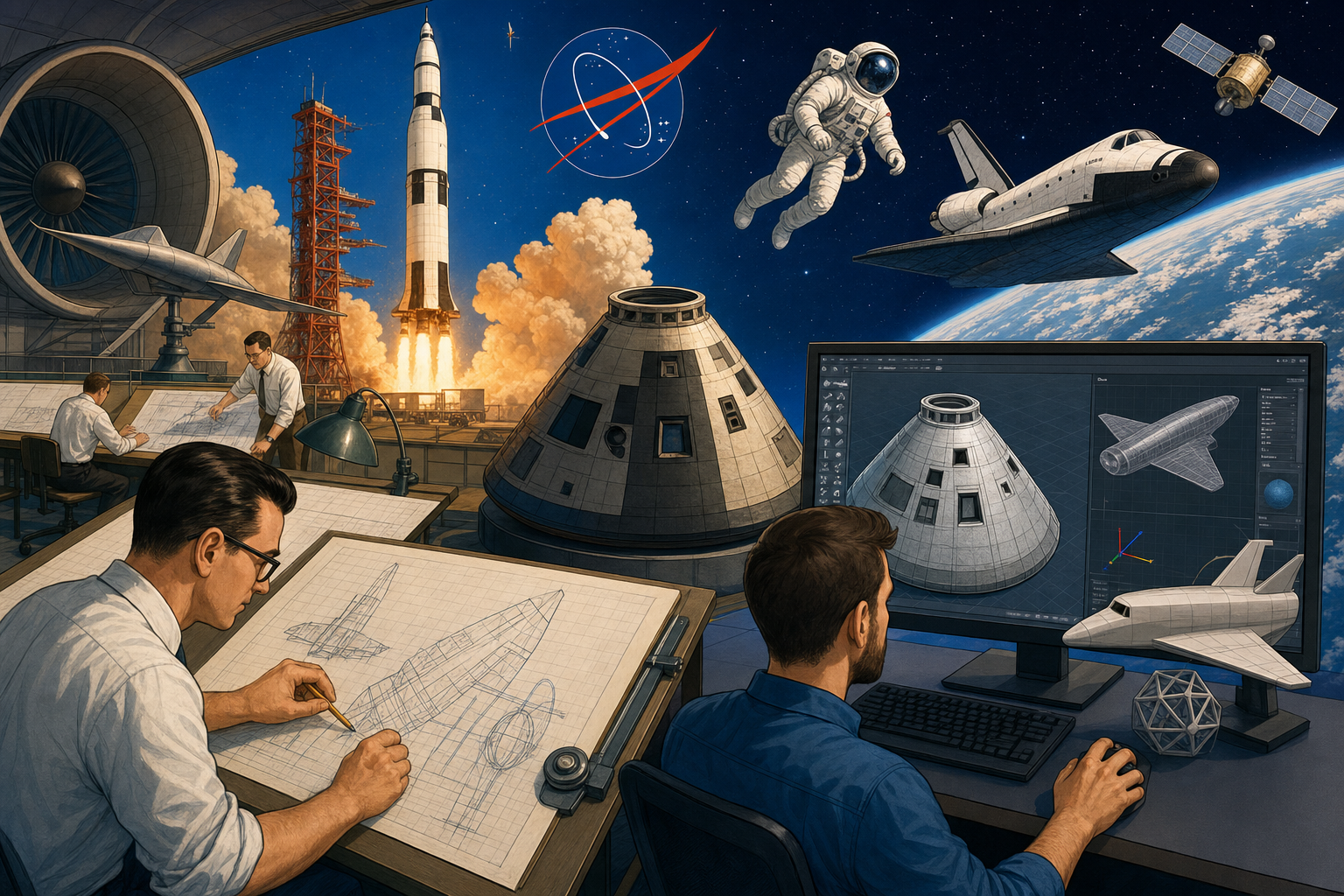


NASA did not invent 3D modeling alone, but the agency and its aerospace ecosystem created some of the strongest reasons for 3D modeling to become practical, mathematical, visual, and production-ready.
NASA’s Computing Problem: Aerospace Needed 3D Before Most Industries
Complex machines exceeded the capacity of paper
Aerospace became one of the first environments where three-dimensional design was not a luxury but a necessity. Aircraft and spacecraft were filled with shapes that could not be described adequately by ordinary orthographic drawings: swept wings, blended fuselages, inlet ducts, rocket nozzles, fairings, heat shields, turbine passages, and structural frames nested inside curved outer skins. These were not decorative surfaces. They controlled drag, lift, stiffness, stability, thermal response, manufacturability, weight, and safety. A small discontinuity in an aerodynamic surface could affect airflow; a small mismatch in a structural interface could delay assembly; a small error in a tool path could ruin an expensive part. Aerospace organizations therefore faced a design problem that was geometric, computational, organizational, and economic at the same time. The geometry had to be precise, the assemblies were enormous, the tolerances were tight, and the cost of building full physical prototypes was extraordinarily high. In that environment, 3D modeling emerged as an engineering control system, not merely as a better way to draw.
The limits of 2D coordination
Traditional drafting worked well when a product could be decomposed into manageable views, sections, and detail sheets, but aircraft and spacecraft stretched that method to its breaking point. A large aerospace program might involve thousands of engineers, suppliers, analysts, tool designers, manufacturing planners, and quality specialists, all interpreting drawings from different perspectives. When a wing rib, hydraulic line, wiring harness, access panel, and fuel tank occupied the same physical volume, coordinating them through separate 2D drawings became slow and risky. Each drawing was an abstraction; the real vehicle was a spatial object. Physical lofting, in which full-size layouts and templates were used to define curved shapes, was essential to early aircraft production, but it required painstaking manual work and constant translation between mathematical intent and shop-floor reality. The more complex the surface, the harder it became to preserve the intended shape through multiple drawing revisions, templates, fixtures, and inspection procedures. Aerospace exposed a fundamental weakness of 2D drafting: it could represent geometry, but it could not reliably manage spatial relationships across a complete engineered system.
NASA as sponsor, customer, and technical pressure source
NASA amplified these demands because its programs combined extreme performance requirements with extreme consequences for failure. Langley Research Center had a long tradition in aerodynamics, wind tunnel testing, structural dynamics, and aircraft research; Ames Research Center contributed to aerothermodynamics, computational fluid dynamics, and visualization; Marshall Space Flight Center carried enormous responsibility for propulsion, launch vehicle structures, and systems integration. These centers did not merely consume commercial design software after it appeared. They supported, evaluated, and pressured computational methods that would later influence design technology more broadly. The space program demanded better definitions of surfaces, better predictions of structural loads, better thermal and fluid analysis, and better manufacturing coordination between government laboratories and contractors. Rockets, capsules, aircraft, lifting bodies, and orbital systems required geometry that could move between analysis, tooling, simulation, and inspection with less ambiguity than paper allowed. In this sense, NASA became both a research sponsor and a demanding customer, helping define the practical expectations that early digital geometry had to satisfy.
Aerospace turned modeling into infrastructure
The central point is that early 3D modeling did not emerge only from the ambition of commercial CAD vendors. It was shaped by government-funded aerospace needs, defense manufacturing, mainframe computing, university research, and the industrial urgency of building vehicles too complex for paper alone. Aerospace made the value of digital geometry unusually obvious because an inaccurate model could lead to an unusable tool, a failed fit check, a wind tunnel discrepancy, or a manufacturing delay costing far more than the computer time required to prevent it. The same industry also demanded that geometric data serve several masters at once: aerodynamicists, stress analysts, NC programmers, production planners, inspection teams, and final assembly crews. This multi-disciplinary pressure made aerospace an early proving ground for ideas that later became normal in CAD: consistent coordinate systems, mathematical surfaces, assembly databases, digital mockups, geometry exchange, and links between design and simulation. The origin story of 3D modeling is therefore partly a story of software, but it is equally a story of aerospace complexity forcing computation into the design process.
- Aerodynamic surfaces required mathematical descriptions rather than approximate drafting alone.
- Large assemblies required spatial coordination across many design teams and suppliers.
- Mission-critical verification demanded analysis-ready geometry and disciplined configuration control.
- Expensive prototypes made digital error detection economically valuable before mainstream industries felt the same urgency.
From Numerical Control to Digital Geometry
Manufacturing pulled geometry into the computer
The path from manual drafting to 3D modeling did not begin as a clean software revolution. It began with manufacturing pressure, especially the need to machine complex parts accurately. Numerical control, or NC, created a new relationship between geometry and production because a machine tool could follow coordinates generated from mathematical descriptions rather than from manual layout alone. Aerospace manufacturers had strong reasons to adopt NC early: aircraft structures used complex contours, thin walls, compound curves, and precision holes located in relation to curved skins and internal frames. A machinist could not simply infer all of that geometry from drawings without costly interpretation. The computer became useful because it could store points, curves, and tool paths in numerical form, then drive machining operations with repeatable accuracy. MIT’s Servomechanisms Laboratory, working in the 1950s with support from the U.S. Air Force, helped establish this link between computation and manufacturing. The early NC projects were not CAD in the modern interactive sense, but they made a decisive conceptual move: geometry became operational data.
MIT, Sketchpad, and the idea of interactive design
Ivan Sutherland’s Sketchpad, presented at MIT in 1963, demonstrated another essential ingredient: the computer display could become a design medium rather than just a calculation output device. Sketchpad was not an aerospace production system, yet its influence on CAD history is enormous because it introduced interactive graphics, constraints, object instances, and visual manipulation in a way that foreshadowed later design software. Sutherland showed that a designer could work with geometric entities on a screen and that relationships between entities could be encoded computationally. In aerospace, that idea was powerful because geometry was not isolated linework; it was a network of relationships among reference planes, centerlines, station locations, aerodynamic curves, structural members, and manufacturing features. The ability to interact with geometry visually mattered because designers needed to inspect, revise, and understand forms that were difficult to imagine from tables of numbers. Sketchpad helped legitimize the notion that computation could participate directly in design thinking, while aerospace supplied the industrial need that would push such ideas into large-scale production environments.
Early industrial systems connected design and production
Large manufacturers quickly recognized that digital geometry could improve coordination between design departments and manufacturing operations. General Motors’ DAC-1 project, developed with IBM in the 1960s, explored computer-aided design for automotive body surfaces and drafting. Although GM was not an aerospace contractor, DAC-1 shared many technical concerns with aerospace: interactive graphics, surface description, database organization, and the conversion of design intent into manufacturable information. Lockheed’s early CAD/CAM work was more directly tied to aircraft production and helped demonstrate how computing could support engineering drawings, NC preparation, and geometry management. Boeing, McDonnell Douglas, Northrop, Grumman, and Rockwell all had reasons to invest in computational approaches because their products involved massive coordination problems and complicated surfaces. These organizations did not think of CAD as merely replacing pencil drafting. They needed systems that could define geometry accurately, support tooling, reduce rework, and preserve consistency across thousands of details. That requirement pushed early software toward databases, coordinate transformations, graphics terminals, and increasingly sophisticated modeling kernels.
Why aerospace surfaces were mathematically difficult
Aerospace geometry was difficult because the most important shapes were smooth, continuous, and functionally sensitive. A fuselage fairing could not be represented as a collection of disconnected arcs without creating problems in aerodynamic analysis and tooling. A wing surface needed controlled curvature, not just a visually acceptable outline. Intersections between ducts, skins, frames, control surfaces, and access panels had to be computed reliably. If two mathematical surfaces met incorrectly, the error might appear later as a tooling mismatch or structural interference. This is why spline curves, surface patches, and continuity conditions became so important. Bézier curves, B-splines, Coons patches, and later NURBS offered ways to describe freeform shapes with mathematical control. Pierre Bézier at Renault and Paul de Casteljau at Citroën advanced curve methods in automotive design, while Steven Coons at MIT contributed influential surface formulations. These ideas were not confined to aerospace, but aerospace gave them severe tests because visualization alone was not enough. The model had to support analysis, tooling, manufacturing, and verification.
- Spline curves allowed designers to define smooth shapes through controlled mathematical relationships.
- Surface patches made it possible to build complex outer mold lines from connected regions.
- Wireframe models provided early spatial representations, though they often lacked topological certainty.
- Hidden-line removal improved visual comprehension of complex structures on graphics displays.
- Solid modeling concepts promised more reliable mass properties, interference checks, and manufacturable definitions.
Digital models had to do more than look convincing
The distinction between visualization and engineering geometry became crucial. A shaded image of an aircraft component might help reviewers understand a shape, but aerospace required much more. Designers needed to know whether one part intersected another, whether a surface was continuous enough for aerodynamic requirements, whether a cutter could machine a feature, whether finite element meshes could be generated, and whether the definition could be controlled through revisions. Wireframe models were useful but ambiguous; they could show edges without guaranteeing the existence of valid surfaces or volumes. Surface modeling improved the representation of aerodynamic forms, but it still required careful trimming, intersection, and continuity management. Solid modeling promised stronger guarantees because it represented bounded volumes with topology, faces, edges, and vertices. Research on boundary representation and constructive solid geometry, associated with institutions and figures such as Ian Braid, Bruce Baumgart, Aristides Requicha, Herb Voelcker, and the Production Automation Project at the University of Rochester, would later shape robust modeling systems. Aerospace helped create the appetite for these capabilities because the geometry had to be trustworthy.
Contractors, Mainframes, and the Birth of Industrial 3D Systems
Aerospace contractors turned experiments into production tools
Major aerospace contractors were essential because they transformed laboratory graphics and geometric algorithms into industrial systems used under schedule pressure. Boeing, Lockheed, McDonnell Douglas, Northrop, Grumman, and Rockwell operated in a world where digital geometry had direct consequences for aircraft assembly, tooling lead time, engineering change control, and supplier coordination. They possessed the scale, budgets, and technical staff to justify mainframes, graphics terminals, specialized software, and internal development groups. These companies also had unusually demanding users: loft engineers who understood physical templates, aerodynamicists who understood curvature, structural analysts who needed load paths, NC programmers who needed cutter motion, and production engineers responsible for thousands of parts arriving at final assembly. A computer system that merely produced clean drawings was insufficient. It had to become a shared technical environment where geometry could be created, interrogated, revised, plotted, machined, and checked. In this setting, early CAD/CAM evolved less like office software and more like industrial infrastructure for complex vehicle design.
IBM, graphics terminals, and high-end computing ecosystems
IBM played a major role because many early industrial CAD installations depended on mainframe computing power, database management, and specialized graphics hardware. Mainframes were expensive, centralized, and operationally demanding, but they offered the computational resources needed for large engineering organizations before workstations became common. IBM’s relationship with aerospace manufacturers helped technology move from custom internal systems toward more repeatable commercial offerings. Evans & Sutherland, founded by David Evans and Ivan Sutherland in 1968, supplied high-performance graphics systems that became important for simulation, visualization, and high-end design applications. Their hardware helped engineers view complex models with a level of interactivity that ordinary terminals could not provide. This mattered because aerospace geometry was spatial and dynamic: engineers needed to rotate, inspect, section, and interpret assemblies that were too complex for static plots alone. The hardware history is easy to overlook, but early 3D modeling was restricted not only by algorithms but by display devices, memory, processing speed, storage, and input technology. Without advanced graphics hardware, many modeling ideas would have remained impractical.
Lockheed, CADAM, and production drafting discipline
CADAM, often associated with Lockheed and IBM, became one of the influential systems in production drafting and manufacturing documentation. Its origins reflected the practical needs of aircraft programs, where drafting consistency, revision control, and manufacturing clarity were essential. CADAM was not famous primarily as a freeform 3D sculpting environment; its importance lay in showing how computer-aided drafting could operate at industrial scale and support disciplined engineering production. In aerospace, 2D did not disappear when 3D arrived. Drawings, specifications, manufacturing notes, inspection plans, and release procedures remained vital. What changed was the growing expectation that drawing geometry should relate to digital definitions and production processes rather than exist as isolated artwork. CADAM helped normalize computer-based drafting among organizations that required accuracy, repeatability, and configuration discipline. It also illustrates a broader historical point: the road to 3D modeling included strong 2D production systems because aerospace needed reliable documentation as much as advanced surfaces. The digital transformation was cumulative, building from drafting and NC toward integrated modeling.
Dassault, CATIA, and the aerospace origin of a global CAD platform
CATIA is one of the clearest examples of aerospace requirements shaping commercial 3D CAD. It grew out of Dassault Aviation’s internal need for advanced design and manufacturing tools, particularly as aircraft geometry became too complex for older drafting-centered approaches. The system emerged from work related to Dassault’s use of CADAM and the development of three-dimensional surface design capabilities. In 1981, Dassault Systèmes was created to commercialize CATIA, with IBM serving as a major distributor. CATIA’s aerospace roots were central to its identity: it was built to manage complex surfaces, large assemblies, tooling relationships, and industrial product definitions. Over time it became influential far beyond aircraft, especially in automotive and high-end manufacturing, but its priorities remained visibly aerospace-derived. Surface quality, coordinate control, assembly structure, and links to manufacturing were not optional features; they were foundational. CATIA’s later role in digital mockup reinforced this lineage because aerospace wanted to replace physical coordination mockups with validated digital assemblies whenever possible. That ambition became one of the defining trends in modern CAD.
Boeing and the push toward digital mockup
Boeing became a major force in digital aircraft design because the company faced one of the hardest coordination problems in manufacturing: assembling large airliners from millions of parts supplied by complex organizational networks. While the full digital mockup era is often associated with later programs, the roots were planted earlier in the aerospace drive for precise geometry management. Boeing’s adoption of advanced CAD/CAM, including CATIA for major aircraft development, reflected a strategic belief that a shared digital product definition could reduce errors, improve fit, and shorten design-to-production cycles. Digital mockup was not simply 3D visualization; it was the use of geometric databases to check spatial relationships, assembly sequences, maintainability, tooling access, and interference conditions before physical build. This approach required software capable of handling large assemblies, hierarchical product structures, coordinate systems, and geometry exchange across teams. The digital mockup idea shows why aerospace pushed CAD beyond drawing automation. A full aircraft could not be understood as a stack of drawings alone; it had to be managed as a coherent spatial product model.
McDonnell Douglas, Northrop, Grumman, Rockwell, and the defense design environment
Other aerospace and defense contractors contributed to the same technological climate. McDonnell Douglas had deep experience in military aircraft, commercial aircraft, and spacecraft systems, all of which demanded strong geometric coordination and analysis workflows. Northrop’s aircraft programs required precise aerodynamic and structural integration, especially for advanced configurations where shape and performance were tightly linked. Grumman, known for naval aircraft and lunar module work, operated in domains where packaging, weight, reliability, and assembly access were critical. Rockwell, involved in aircraft and space systems including major work associated with the Space Shuttle program, faced integration problems involving thermal protection, structures, propulsion interfaces, avionics, and manufacturing constraints. These companies varied in their internal tools and vendor relationships, but they shared the same pressure: they needed computation to manage geometry at a scale and precision that manual methods could no longer support efficiently. The aerospace contractor ecosystem became a demanding market that rewarded better surface modeling, better assembly management, better plotting, better NC integration, and better data control.
- Large assembly management became essential because aircraft and spacecraft contained thousands to millions of defined items.
- Surface modeling was necessary for aerodynamic skins, inlets, fairings, nacelles, and control surfaces.
- Design-analysis integration grew in importance as computational fluid dynamics and finite element analysis matured.
- Manufacturing links connected digital geometry to NC machining, tooling, inspection, and production planning.
- Data consistency became a strategic requirement because disconnected geometry caused expensive downstream errors.
Commercial systems absorbed aerospace expectations
Several commercial systems evolved under pressure from high-end engineering customers whose needs were shaped by aerospace, defense, automotive, and heavy manufacturing. Unigraphics, with roots connected to United Computing and later McDonnell Douglas Automation before becoming part of the EDS and Siemens PLM lineage, developed into a powerful CAD/CAM/CAE platform. Intergraph, founded by former IBM engineers and strongly associated with engineering graphics and plant design, supplied systems for complex technical environments where visualization and data management mattered. Applicon, Computervision, SDRC, and later Parametric Technology Corporation all participated in a competitive market in which customers increasingly demanded robust geometry, assemblies, drafting, manufacturing output, and analysis links. Aerospace buyers were particularly influential because they exposed weaknesses quickly. If a system could not manage coordinate transformations, surface intersections, hidden-line views, or data exchange, those weaknesses became production problems. Many features taken for granted today had to mature under these pressures: reference geometry, layers, assemblies, model interrogation, mass properties, interference detection, version control, and neutral file exchange formats such as IGES, which was developed with participation from the U.S. National Bureau of Standards and industry partners.
Geometry exchange and organizational complexity
Aerospace also made geometry exchange unavoidable. No major aircraft or spacecraft was designed by a single isolated group using one perfect software environment. Government agencies, prime contractors, subcontractors, suppliers, universities, and laboratories all needed to share geometry and analysis information. This created a persistent demand for data standards and translation methods. IGES, first published in 1980, was one response to the need for exchanging product definition data among dissimilar CAD systems. Later STEP, governed by ISO 10303, aimed at richer product model exchange beyond basic geometry. These standards were motivated by broad industry needs, but aerospace was one of the environments where the cost of failed translation was most visible. A mistranslated surface, lost coordinate frame, or changed tolerance could affect tooling or analysis. Digital geometry therefore became not just a modeling issue but an information governance issue. The model had to carry meaning across software boundaries, organizational boundaries, and time. That expectation continues to shape modern product lifecycle management and model-based engineering.
How NASA-Era Aerospace Demands Shaped Modern 3D Modeling
The aerospace agenda remains visible in modern CAD
Modern CAD systems still reflect priorities sharpened by NASA-era aerospace demands. Precise geometry is expected; complex surfaces are expected; assemblies with thousands of components are expected; interference checking is expected; links to simulation and manufacturing are expected. These expectations did not become universal because every designer needed to build a launch vehicle. They became universal because the most demanding industries proved that digital product definition could reduce ambiguity and coordinate work better than paper alone. Aerospace forced software developers to treat 3D models as authoritative engineering objects rather than presentation graphics. That is why today’s systems support parametric features, associative drawings, surface continuity tools, finite element preprocessing, CAM tool paths, geometric dimensioning and tolerancing, configuration control, and product data management. The lineage is not perfectly linear, and many industries contributed important innovations, but the aerospace influence is unmistakable. Rockets, aircraft, and spacecraft made it clear that the value of a model lies in its ability to connect design intent with verification and production.
From specialized machines to ordinary design work
There is a historical irony in this progression. Tools and methods originally justified by rockets, military aircraft, spacecraft, and expensive defense programs eventually changed everyday product design. Automotive styling absorbed high-end surface modeling. Consumer product design adopted solid modeling, rendering, assembly checks, and rapid prototyping workflows. Architecture absorbed 3D coordination, clash detection, parametric modeling, and digital visualization through building information modeling and computational design. Additive manufacturing further expanded the importance of digital geometry because the model could become a direct manufacturing source rather than merely a drawing reference. Many designers now rotate shaded models on inexpensive laptops with more ease than early aerospace engineers could achieve on costly mainframes and graphics terminals. Yet beneath that convenience are concepts matured in demanding technical environments: splines, surfaces, solids, coordinate systems, assemblies, hidden-line algorithms, visualization pipelines, neutral exchange standards, and analysis-ready representations. The democratization of 3D modeling did not erase its aerospace ancestry. It made that ancestry ordinary.
The deeper lesson of early 3D modeling history
The history of early 3D modeling is not only a story of software companies competing to replace drafting boards. It is a story of national research programs, aerospace contractors, university laboratories, mathematical geometry, expensive hardware, manufacturing automation, and the need to design machines too complex for paper alone. NASA centers such as Langley, Ames, and Marshall helped create the research and performance environment in which computational methods mattered deeply. Contractors such as Boeing, Lockheed, McDonnell Douglas, Northrop, Grumman, Rockwell, and Dassault Aviation turned geometric computing into production practice. IBM and Evans & Sutherland supplied parts of the computing and graphics infrastructure. Researchers such as Ivan Sutherland, Steven Coons, Pierre Bézier, Paul de Casteljau, Aristides Requicha, Herb Voelcker, and others contributed ideas that made interactive and mathematical modeling possible. The result was a transformation in what an engineering model could be. It became not only a representation of a product, but a computable, exchangeable, analyzable, manufacturable definition of one.
- NASA and aerospace contractors made 3D modeling necessary before it became mainstream.
- Mathematical geometry gave designers a way to define smooth, precise, manufacturable forms.
- Mainframes and graphics hardware made early industrial modeling possible, despite great cost and complexity.
- Digital mockup and assembly checking transformed the model from an image into a verification environment.
- Modern CAD still carries the aerospace inheritance of precision, simulation, manufacturing integration, and large-scale coordination.
A final perspective
The rise of 3D modeling should be understood as a response to complexity. Aerospace reached that complexity earlier than most industries because flight vehicles are unforgiving combinations of shape, structure, systems, weight, performance, and safety. NASA’s programs and the broader aerospace contractor network created a world in which approximate drawings, manual templates, and disconnected calculations were no longer enough. Computers offered a way to define geometry with mathematical discipline, visualize it interactively, analyze it numerically, manufacture it more directly, and coordinate it across vast engineering organizations. That is the deeper legacy of NASA-era aerospace demands. They helped shift design from a document-centered activity toward a model-centered activity. Today, when a designer checks interference in an assembly, smooths a Class A surface, exports a manufacturing file, prepares a simulation mesh, or reviews a digital mockup, they are using practices shaped by decades of aerospace pressure. What began as specialized infrastructure for aircraft, rockets, and spacecraft became one of the foundations of modern design software.
Also in Design News






