Your Cart is Empty


Design Software History: From Booleans to Feature Trees: The Evolution of Solid Modeling in CAD
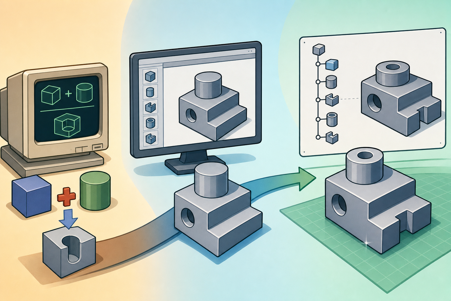


CAD became transformative when it stopped behaving like an electronic drafting board and began representing objects as manufacturable volumes. That shift required geometry, topology, numerical methods, and engineering judgment to converge into a new kind of computational object.
Solid Modeling Before Design Intent
From drawing to object representation
The first great ambiguity in computer-aided design was deceptively simple: could a computer model represent a real object, or could it only draw a picture of one? Early CAD systems were born in a culture of drafting, where the deliverable was a line drawing, a projection, a dimensioned view, or a plotted sheet. The intellectual roots go back to Ivan Sutherland and his 1963 Sketchpad system at MIT Lincoln Laboratory, which demonstrated that interactive graphics could be constrained, edited, and manipulated in ways that resembled design reasoning rather than mere illustration. Yet Sketchpad’s brilliance did not immediately solve the central problem of manufacturing representation. A two-dimensional drawing could describe a bracket, turbine blade, fixture, or housing, but the computer did not necessarily “know” what material existed, what was empty space, or whether two views were mutually consistent. The representation problem became urgent as aerospace, automotive, defense, and machine-tool industries tried to use digital models not only for drafting, but also for numerical control, mass properties, interference checking, and engineering analysis.
The limits of wireframes and surfaces
The progression from 2D drafting to wireframe modeling and then to surface modeling revealed both progress and insufficiency. Wireframe models allowed designers to visualize three-dimensional forms using vertices and edges, but they had no reliable notion of inside and outside. A cube drawn as twelve edges could be interpreted visually as a box, yet mathematically it was only a graph in space unless additional rules defined its faces and enclosed volume. Surface modeling improved realism and became essential for automotive body design, ship hulls, aircraft skins, and consumer product forms, especially where smooth curvature mattered. Companies such as Renault, Boeing, General Motors, and Dassault were deeply invested in high-quality surface definition, while mathematical tools such as Bézier curves, B-splines, and later NURBS made complex shape description practical. Still, a collection of surfaces could be incomplete, self-intersecting, or inconsistently oriented. Without a coherent volume model, downstream software could not safely compute section properties, tool paths, mold splits, or interference relationships. The industry needed a stronger mathematical contract.
CSG and B-Rep as competing foundations
Two foundational approaches emerged to answer that contract: Constructive Solid Geometry and Boundary Representation. CSG described solids as combinations of primitive volumes such as blocks, cylinders, cones, spheres, and toroids, joined through Boolean operations. A model was not primarily a skin; it was an expression tree defining how volumes were added, subtracted, or intersected. B-Rep, by contrast, described a solid through its boundary: faces, edges, vertices, and the topological relationships among them. This helped the modeler understand precisely which face bordered which edge, how loops defined trimmed regions, and how a closed shell separated material from empty space. Researchers such as Ian Braid at Cambridge, Bruce Baumgart at Stanford, and others working on early topological structures made B-Rep a serious computational discipline rather than a rendering trick. The opposing styles were not merely programming preferences. CSG emphasized validity by construction, while B-Rep emphasized explicit editable shape. Both would become indispensable to commercial CAD.
Rochester and the mathematical definition of validity
At the University of Rochester, Ari Requicha and Herb Voelcker helped frame solid modeling as a rigorous branch of engineering computation. Their work around the PADL systems, often associated with the phrase “Part and Assembly Description Language,” stressed that a solid model had to be unambiguous, valid, and suitable for automated reasoning. This was a crucial philosophical step. A graphic display could tolerate gaps, overlaps, and visually plausible shortcuts, but an engineering model used for manufacturing could not. A valid solid needed to occupy a well-defined subset of three-dimensional space; it needed a determinate boundary; and it needed operations whose results were mathematically meaningful. Requicha’s writings on regularized set operations, representation schemes, and formal validity helped the CAD community recognize that solid modeling was not just about drawing prettier shaded images. It was about agreeing on what counted as an object. That agreement became the hidden law beneath later systems, from mainframe CAD environments to desktop parametric modelers.
- 2D drafting captured projected design communication, but not volume.
- Wireframe modeling captured spatial structure, but not enclosed material.
- Surface modeling captured sophisticated shape, but could leave validity unresolved.
- Solid modeling captured objects as computable volumes with topology and boundary rules.
Boolean Operations as the First Language of Solid Creation
Why union, difference, and intersection felt natural
Boolean operations became the first practical language of solid creation because they mirrored physical manufacturing intuition. A machinist removes material from stock; a welder or fabricator joins material; a mold designer considers intersections between a part, a core, and a cavity; an engineer tests whether two components overlap. In computational form these ideas became union, difference, and intersection. Union combines volumes into one object. Difference removes one volume from another. Intersection keeps only the shared region. These operations gave early solid modeling a grammar that was small, powerful, and explainable to engineers. A mounting plate could be modeled as a rectangular block minus cylindrical holes, plus raised bosses, minus pockets, and perhaps intersected with trimming volumes. This procedure also made models auditable. Instead of manipulating thousands of disconnected faces, a designer could describe intent-like construction from meaningful primitive actions. Long before parametric history trees became mainstream, Boolean expressions already hinted that a CAD model could be a recipe, not only a shape.
Compositional power from simple primitives
The power of Booleans came from compositionality. A limited library of analytic primitives could generate a surprisingly wide range of mechanical geometry when repeatedly combined. Blocks, cylinders, cones, spheres, wedges, and swept shapes could describe housings, brackets, fixtures, pipe junctions, optical mounts, and many military or industrial components. This mattered because early computers had severe memory and processing limitations. Storing and rendering arbitrary detailed boundaries was expensive, but storing a tree of primitive definitions and Boolean operators could be compact. Moreover, CSG objects were often easier to classify conceptually: if primitives were valid solids and operations were regularized, the resulting object could remain valid. That promise was extremely attractive to researchers trying to avoid the ambiguities of dangling wireframes and leaky surfaces. However, the elegance was partly theoretical. To display a CSG model, manufacture it, mesh it, or check it against another part, the system usually had to evaluate the Boolean expression into boundary information. That evaluation exposed the hard computational geometry beneath the clean symbolic language.
Early systems that shaped the Boolean imagination
Several early systems gave Boolean solid modeling industrial credibility. MAGI’s SynthaVision, developed by Mathematical Applications Group, Inc., became famous in computer graphics history for constructive solid techniques and for its role in early cinematic imagery, including work connected to the 1982 film “Tron.” Its relevance to CAD history lies in how it demonstrated that complex visual and spatial forms could arise from combinations of solid primitives. BUILD, developed by Ian Braid, was instrumental in making boundary-based solid modeling research concrete and influential. Romulus, developed from research lineage associated with Braid and Shape Data in Cambridge, became one of the first commercial solid modeling kernels and influenced later kernel architecture. BRL-CAD, originating at the U.S. Army Ballistic Research Laboratory, brought CSG thinking into defense, survivability analysis, and engineering simulations where object validity and intersection calculations had mission-critical importance. These systems occupied different markets and technical cultures, but collectively they proved that solids were no longer an academic curiosity. They could support analysis, visualization, and manufacturing workflows.
- MAGI’s SynthaVision showed how primitive-based solid construction could create complex computed geometry.
- BUILD helped establish ideas that shaped practical solid modeling research.
- Romulus demonstrated that solid modeling kernels could become commercial infrastructure.
- BRL-CAD proved the durability of CSG in serious engineering and defense applications.
The algorithmic difficulty hidden behind clean operators
Boolean operations looked simple in textbooks, but they were algorithmically demanding in production software. When two solids intersect, the system must compute curve intersections between surfaces, split faces, classify regions as inside or outside, rebuild topology, remove invalid fragments, and maintain numerical consistency. Analytic surfaces such as planes and cylinders are manageable until they meet trimmed splines, tangencies, near-coincident edges, microscopic sliver faces, or badly conditioned input. Numerical tolerance becomes a philosophical and practical problem: if two edges are separated by a millionth of a millimeter, are they identical, separate, or evidence of a modeling failure? Solid modelers must make this decision repeatedly while preserving topology that users experience as reliable geometry. A Boolean difference that produces an unexpected missing face is not merely a display bug; it can ruin a mold design, corrupt a tool path, or invalidate a mass-property calculation. Early kernel developers learned that solid modeling required a balance between exact mathematical definitions and robust engineering approximations. That tension still defines commercial CAD kernels today.
The productive tension between CSG and B-Rep
CSG was elegant because the construction tree could preserve a compact statement of how a form was made, but B-Rep was indispensable because engineers needed to select faces, fillet edges, shell bodies, draft walls, trim surfaces, and create manufacturing details at the boundary level. Visualization also favored B-Rep because shaded rendering, hidden-line removal, and face-based interaction depended on explicit boundaries. Feature modeling later intensified this preference. A hole feature might begin conceptually as a cylinder subtracted from a body, but users wanted to edit its placement by selecting a planar face, referencing edges, changing a diameter dimension, or patterning it around an axis. Those operations depended on topological entities that CSG alone did not expose naturally. The historical tension was therefore not a battle with a single winner. Instead, the modern CAD system became a hybrid machine. It used Boolean logic as a volumetric engine, B-Rep as an interaction and evaluation structure, and later parametric constraints as the mechanism by which engineers edited the recipe of creation.
From Boolean Operations to Feature-Based Modeling
The arrival of features as engineering language
The transition from Boolean construction to feature-based modeling occurred when CAD vendors realized that engineers did not think only in primitives and set operations. They thought in holes, ribs, bosses, pockets, pads, slots, chamfers, fillets, shells, drafts, patterns, and mounting interfaces. A cylinder subtracted from a block is mathematically a Boolean difference, but an engineer calls it a drilled hole or a counterbore, and expects it to carry manufacturing meaning. Feature-based modeling translated low-level geometric operations into user-facing engineering vocabulary. This was not simply a convenience layer. It changed how design work was structured. A feature could have parameters, constraints, references, and semantic behavior. A hole could know its diameter, depth, termination condition, thread standard, placement sketch, and relationship to neighboring faces. A fillet could propagate along tangent edges. A shell could remove selected faces and offset remaining walls. These higher-level operations made CAD more productive, but they also increased the burden on the underlying kernel, which still had to execute reliable Boolean and B-Rep operations beneath every feature.
What the history tree actually records
The history tree became the visible timeline of engineering decisions. It recorded sketches, reference planes, extrusions, revolutions, sweeps, lofts, cuts, fillets, holes, shells, drafts, patterns, mirrors, equations, constraints, and assembly references in chronological order. In principle, this converted a model from a static body into an editable procedure. If a designer changed the thickness of a base extrusion from 10 millimeters to 12 millimeters, downstream holes, bosses, and cuts could rebuild according to their constraints. If a sketch dimension changed, the entire part could update. This was revolutionary because it allowed engineering iteration without recreating geometry manually. It also joined geometric modeling to design intent, a phrase that came to describe the expected behavior of a model under change. Design intent was never only about shape; it was about relationships. A hole should remain centered, a rib should maintain wall thickness, a bolt pattern should preserve equal spacing, and a fillet should follow a functional edge even as surrounding geometry evolves.
- A history tree stores chronological modeling operations, not merely the final visible body.
- Sketch dimensions and constraints allow geometry to be regenerated after edits.
- Feature references create parent-child dependencies across the model.
- The model becomes an editable recipe whose success depends on stable topology.
PTC Pro/ENGINEER and the parametric break
PTC Pro/ENGINEER, introduced by Parametric Technology Corporation in the late 1980s under the leadership of Samuel Geisberg, made parametric, feature-based solid modeling a commercial force. Earlier CAD systems had explored constraints and procedural construction, but Pro/ENGINEER packaged these ideas into a disciplined approach that changed expectations across mechanical design. Dimensions did not merely annotate geometry; they drove it. Constraints did not merely document intention; they regenerated shape. Features were not isolated editing commands; they existed in a dependency structure. The implications were profound. Engineers could create families of parts, update models after late design changes, and maintain relationships between components in assemblies. A bracket could grow wider while its bolt holes remained symmetric. A housing could change wall thickness while bosses and ribs adapted. This approach reframed CAD models as executable engineering memory. The model remembered not only what shape had been produced, but also the sequence of assumptions and relationships that produced it, making revision a central design activity rather than a painful redrawing exercise.
How competitors and kernels shaped the mainstream
The rise of feature-based modeling unfolded across a competitive ecosystem. Dassault Systèmes CATIA, with origins connected to Dassault Aviation, became a dominant system in aerospace and automotive design, especially where complex surfaces, assemblies, and enterprise-scale processes mattered. Unigraphics, later evolving into Siemens NX, carried strong manufacturing and high-end mechanical design capabilities. SolidWorks, founded in the 1990s and later acquired by Dassault Systèmes, brought parametric solid modeling to a broader Windows-based engineering audience and helped define expectations for accessible feature trees. Autodesk Inventor extended Autodesk’s reach from drafting-centered AutoCAD culture into parametric mechanical modeling. Beneath many applications were geometric kernels that served as industrial engines. ACIS, associated with Spatial Technology, and Parasolid, associated with Shape Data, Unigraphics Solutions, and later Siemens, provided low-level modeling functions including B-Rep management, Booleans, blending, offsetting, and surface operations. These kernels mattered because the visible elegance of a feature tree depended on the invisible reliability of intersection, classification, and topology algorithms.
The hidden cost of editable history
History trees gave engineers extraordinary power, but they also introduced fragility. Every feature can depend on earlier geometry, and every selected edge or face can become a vulnerable reference. If an upstream cut removes a face that a downstream sketch used as a plane, the model may fail. If a fillet changes the topology around an edge, a pattern or chamfer may lose its target. If a Boolean operation creates a different face naming sequence after regeneration, later features may attach to the wrong entity or fail entirely. Users developed the practical art sometimes called “feature tree archaeology,” where an engineer investigates old models to discover why a rebuild failed, which parent feature controls a dimension, or why a sketch is underconstrained. This fragility is closely tied to the famous topological naming problem: how does software preserve the identity of a face or edge across changes that alter the boundary? CAD vendors have spent decades improving reference stability, diagnostics, rollback tools, and direct editing, but editable history remains both a gift and a liability.
- Failed rebuilds occur when downstream operations can no longer resolve their inputs.
- Broken references often arise from deleted, split, merged, or renamed faces and edges.
- Parent-child dependencies make models powerful but sensitive to upstream changes.
- Feature tree archaeology becomes necessary when design logic is old, undocumented, or overly complex.
Boolean Logic Inside the Modern Feature Tree
Features are often Booleans wearing engineering clothes
Although modern CAD interfaces rarely ask users to think explicitly in Boolean algebra, Boolean logic still lives inside almost every solid modeling workflow. An extruded boss is typically a union between an existing body and a swept sketch region. An extruded cut is a Boolean difference. A revolved cut removes a rotational volume. A hole feature subtracts a cylindrical or compound tool body, often with countersink, counterbore, or thread-related geometry. A mold cavity may be derived through subtraction between a stock block and a part body. Split bodies, trims, ribs, bosses, and certain sheet metal operations all rely on classification of material and empty space. Even when the interface presents friendly icons and manufacturing language, the kernel must decide which regions remain, which boundaries survive, and how topology is rebuilt. The history tree made the recipe visible, but the recipe still calls the same deep operations developed in the early era of solid modeling. The modern feature is therefore a semantic wrapper around very old geometric commitments.
B-Rep remains the editable and visual surface of the model
At the same time, B-Rep remains central because users interact with boundaries. Designers select faces to sketch on, edges to fillet, loops to offset, vertices to dimension, and surfaces to thicken or trim. Assemblies use faces and axes for mates. Drawings extract edges and silhouettes. Simulation tools mesh faces and volumes. CAM systems calculate tool contact against surfaces. Additive manufacturing workflows triangulate boundaries into mesh formats, even when the design originates as a precise solid. This means modern CAD lives in a layered condition: the user sees features and design intent, the modeling kernel manages B-Rep topology, and Boolean operations alter volume. Historically, this layered architecture is the reconciliation of CSG and B-Rep rather than the victory of one over the other. A designer changing a parametric dimension may believe they are editing design intent, but the system is also recomputing intersections, trimming faces, assigning tolerances, and maintaining a valid closed shell. The apparent simplicity of feature editing depends on a dense stack of geometric machinery.
Direct modeling and the continuing argument about intent
The growth of direct modeling did not eliminate history-based CAD; it exposed its limits. Systems and technologies such as Siemens’ synchronous technology in NX and Solid Edge, direct editing in SpaceClaim, and later direct manipulation tools across mainstream CAD offered ways to push, pull, move, delete, and reblend geometry without always navigating a long parent-child tree. This revived older questions in a new form. Should a CAD model preserve the chronological intent of its creation, or should it behave like an intelligent solid body that can be edited directly? History-based modeling excels when families of parts, controlled variants, and precise design rules are required. Direct modeling excels when imported geometry lacks history, when late-stage edits must be fast, or when the original construction logic is irrelevant. Yet even direct modeling relies on the same underlying requirements: valid solids, robust Booleans, coherent B-Rep topology, and reliable classification. The debate is not between old and new CAD. It is between different interfaces to the same persistent mathematical problem.
Why the Original Solid Modeling Questions Still Matter
Mathematical rigor versus modeling flexibility
Modern CAD still balances the same tensions that shaped early solid modeling research: mathematical rigor versus modeling flexibility, editable history versus direct manipulation, and clean topology versus real-world design messiness. Mathematical rigor demands valid solids, watertight boundaries, consistent normals, non-self-intersection, and predictable Boolean results. Modeling flexibility demands that engineers be allowed to create complex blends, imported supplier geometry, organic surfaces, thin features, offsets, shells, and last-minute edits under schedule pressure. These goals conflict often. A design that looks acceptable on screen may contain tiny gaps, sliver faces, or near-tangent intersections that complicate meshing, machining, or 3D printing. Additive manufacturing has made this especially visible: a model intended for printing must ultimately define a closed volume, even if it began as surfaces, lattices, scans, or generative geometry. The historical lesson from Requicha, Voelcker, Braid, Baumgart, and the early kernel developers remains current. The computer must know what is material and what is not. Without that distinction, downstream automation becomes unreliable.
Executable engineering memory as the real achievement
The journey from Booleans to history trees is the story of CAD becoming less like digital sculpture and more like executable engineering memory. A sculptural model can express form, but an engineering model must remember constraints, dimensions, manufacturing assumptions, symmetry, fit, function, and revision logic. Boolean operations provided the first strong language for making volume computable. B-Rep supplied the explicit boundary structure needed for visualization, editing, and downstream processes. Feature-based parametrics turned modeling actions into named engineering operations. The history tree exposed those operations so they could be edited, reordered, suppressed, patterned, diagnosed, and reused. Yet no layer replaced the previous one. Today’s CAD systems still depend on Boolean set logic when cutting holes, adding bosses, splitting tools, generating mold cavities, or deriving intersecting geometry. They still depend on B-Rep topology when selecting and rebuilding faces. They still struggle with references, tolerances, and validity. The remarkable achievement is not that CAD escaped its origins, but that it stacked decades of mathematics and software engineering into tools designers can use every day.
The enduring legacy of Booleans and history trees
In retrospect, the history of solid modeling shows that CAD advanced when it solved representation problems, not merely interface problems. The move from 2D drafting to wireframes, surfaces, solids, Booleans, B-Rep kernels, features, and parametric history was a sequence of deeper agreements about design knowledge. Boolean logic answered how volumes combine. Boundary representation answered how solids expose editable faces, edges, and vertices. Feature modeling answered how engineers describe meaningful manufacturing operations. History trees answered how design decisions can be regenerated after change. The names attached to this evolution—Ivan Sutherland, Ian Braid, Bruce Baumgart, Ari Requicha, Herb Voelcker, Samuel Geisberg, PTC, Dassault Systèmes, Siemens, Autodesk, Spatial, and the teams behind Romulus, ACIS, Parasolid, CATIA, NX, SolidWorks, Inventor, BRL-CAD, and PADL—belong to a continuous technical narrative. The final takeaway is clear: modern CAD is not simply software for making shapes. It is a computational agreement about valid objects, editable decisions, and the memory of engineering intent.
Also in Design News