Your Cart is Empty
Design Software History: Feature-Based Machining in CAD/CAM History


APT and the Formalization of Numerical Control
MIT, the U.S. Air Force, and the language of machining geometry
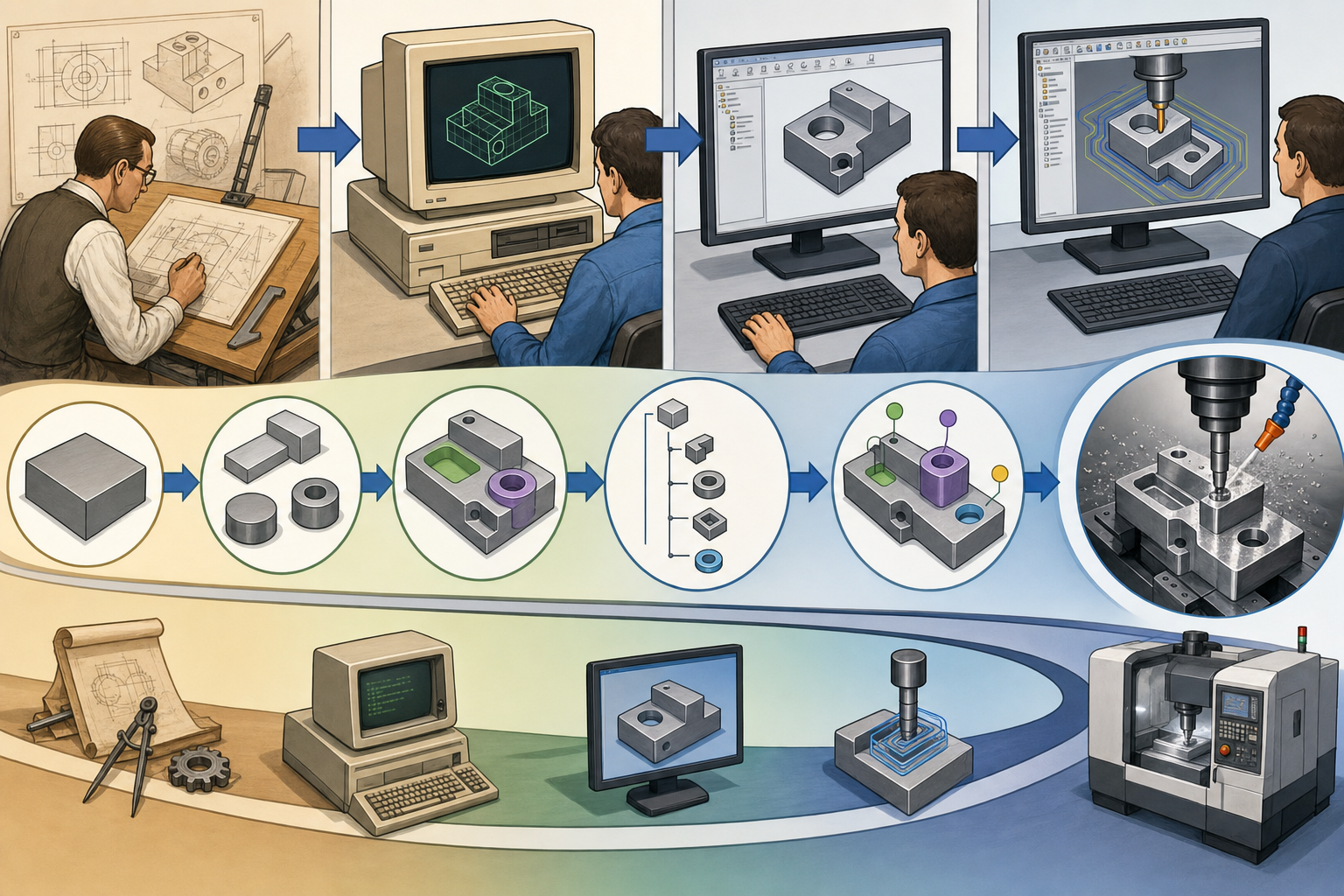
The first major step toward a more systematic approach came through APT, the Automatically Programmed Tool system, developed at the Massachusetts Institute of Technology in the 1950s with significant support from the U.S. Air Force. APT was closely tied to the aerospace industry’s need to machine complex aircraft and missile components with repeatability and mathematical precision. Figures such as Douglas T. Ross at MIT were instrumental in developing the computational concepts behind APT, and the work also connects to the broader history of early computer-aided design at MIT’s Servomechanisms Laboratory. APT allowed programmers to describe geometric entities such as points, lines, circles, planes, and surfaces, then define tool movements relative to those entities. This was a profound improvement over purely manual coordinate calculation, because it introduced a higher-level vocabulary for numerical control. Yet APT still required programmers to think procedurally. It could say, in effect, “move the cutter along this line” or “drive the tool relative to this surface,” but it did not automatically infer that a cylindrical depression was a bored hole requiring a center drill, drill, rough bore, and finish bore sequence. APT formalized NC programming, but it did not yet encode broad manufacturing intent.
The Limits of Early NC and CNC Workflows
Separate geometry, separate process logic, separate expertise
The limitations of early NC and CNC workflows were not merely technical inconveniences; they reflected a deeper separation between design geometry and manufacturing logic. Geometry was commonly captured in drawings, templates, lofts, punched tape instructions, or later CAD databases, while machining decisions existed in process sheets, handwritten notes, and the memory of specialists. A toolpath might be mathematically precise, but the reasoning behind its creation was often invisible to the system. If a programmer selected a particular end mill for an aluminum pocket, used a reduced feed rate for a thin wall, or inserted a spring pass for a tolerance-critical bore, that decision usually disappeared into the final NC code. The next programmer might have to rediscover the same logic. This created several persistent problems:
- Toolpaths were often manually defined even when the underlying feature was common and repetitive.
- Machining methods varied widely between programmers, shifts, plants, and subcontractors.
- Quoting and process planning depended heavily on individual experience rather than reusable software rules.
- Design changes required tedious regeneration of toolpaths, with no guarantee that the same manufacturing reasoning would be preserved.
The historical importance of feature-based machining begins with this weakness. CAM needed to move from describing cutter motion toward representing manufacturable features and the knowledge required to machine them.
The Central Idea of Feature-Based Machining
Programming the feature instead of every cut
Feature-based machining proposed a different relationship between the part model and the machining process. Instead of forcing the programmer to create every operation from raw curves, surfaces, boundaries, and coordinates, the CAM system would identify or define meaningful manufacturing features: drilled holes, tapped holes, counterbores, pockets, slots, bosses, chamfers, planar faces, and profiles. Once a feature was known, the system could associate it with a machining strategy. A simple tapped hole, for example, might trigger a center drill, pilot drill, tap drill, chamfer, tapping cycle, and inspection note. A rectangular pocket might trigger roughing, rest machining, floor finishing, wall finishing, and corner cleanup. The revolutionary premise was that a feature carries process implications. It is not just geometry; it is geometry interpreted through manufacturing practice. This made it possible for CAM software to select tools, feeds, speeds, stepdowns, stepover values, canned cycles, lead-in moves, and operation sequences automatically or semi-automatically. The programmer still mattered, but the system began absorbing repetitive process planning tasks. In historical terms, feature-based machining was one of the first practical attempts to make commercial manufacturing software reason about the part as a machinist might: not as disconnected surfaces, but as categories of work.
The Rise of Features in CAD/CAM Systems
From design features to machining features
The rise of feature-based machining cannot be separated from the rise of feature-based design. In early wireframe and surface modeling systems, geometry was often represented as lines, arcs, curves, and trimmed surfaces. These systems were powerful, especially in aerospace and automotive work, but they did not necessarily preserve the semantic meaning of design operations. A hole was often just a circular edge and a cylindrical face; a pocket was a group of walls and a floor. Parametric, feature-based CAD changed this by making design history part of the model. PTC’s Pro/ENGINEER, introduced in the late 1980s under the leadership of Samuel P. Geisberg and Parametric Technology Corporation, was especially influential because it popularized a modeling approach based on sketches, constraints, dimensions, extrusions, cuts, rounds, holes, patterns, and parent-child relationships. The designer did not merely create final shape; the designer built a history of intent. This raised an obvious manufacturing question: if the CAD system already knows that a feature is a hole, a cut, or a protrusion, why should the CAM programmer have to rediscover that fact from dumb geometry? This question became one of the driving forces behind CAD/CAM integration in the 1990s and 2000s.
Companies That Shaped the Feature-Based Direction
Industrial platforms and the search for integrated manufacturing
Many companies contributed to the shift from geometry drafting and toolpath creation toward integrated, feature-aware manufacturing. Computervision, one of the early giants of CAD/CAM, built systems that connected design data to manufacturing automation at a time when minicomputers and mainframes still dominated industrial computing. Dassault Systèmes, originating from Dassault Aviation’s internal CATIA development, advanced large-scale aerospace workflows where design geometry, NC programming, tooling, and certification requirements had to coexist in a disciplined digital environment. Unigraphics, developed through United Computing and later associated with McDonnell Douglas, EDS, UGS, and ultimately Siemens NX, became one of the most important integrated CAD/CAM/CAE platforms, especially in automotive, aerospace, and tooling. SDRC’s I-DEAS contributed significantly to feature-based solid modeling and engineering workflows before its technology and market position were absorbed into the broader Siemens PLM lineage. PTC pushed parametric feature modeling into mainstream mechanical design, while CAM vendors such as CNC Software with Mastercam, Delcam with PowerMILL and FeatureCAM, and later Autodesk after acquiring Delcam, pursued practical shop-floor automation. FeatureCAM, developed by Engineering Geometry Systems before Delcam acquired it, became particularly associated with feature-based machining because it emphasized automatic recognition and operation generation for common prismatic features. Together, these companies defined the commercial ecosystem in which manufacturing features became a serious software concept.
Two Paths: Recognition and Explicit Feature Programming
Inferring features versus declaring features
As feature-based machining evolved, two major paths emerged. The first was feature recognition, in which the CAM system analyzed imported solid geometry and attempted to identify machinable shapes. This was especially important because much manufacturing data arrived through neutral file formats such as IGES, STEP, Parasolid-based transfer, ACIS-based transfer, or native but history-stripped solid models. A CAM system might examine faces, edges, loops, adjacency relationships, cylindrical surfaces, planar floors, and boundary chains to infer that a certain region was a pocket or that a set of coaxial cylindrical faces represented a counterbored hole. The second path was feature-based programming, where the manufacturing feature was explicitly defined by the user, derived from native CAD features, or created in a controlled CAM environment. This approach reduced ambiguity because the software did not have to guess; the programmer or model history declared the feature’s purpose. Both paths had advantages. Recognition helped shops deal with imported customer models that lacked design history. Explicit feature programming enabled richer rules, predictable automation, and standardized operations. The tension between these paths still exists. Manufacturing systems want the intelligence of explicit features, but real production environments often receive imperfect geometry, incomplete metadata, and models created in many different CAD systems.
How Feature-Based Machining Changed the CAM Workflow
Detection, classification, rules, and operation generation
The technical logic of feature-based machining usually follows a chain of interpretation. First, the software detects a geometry pattern. It may identify cylindrical faces, planar boundaries, closed loops, open-ended slots, intersecting profiles, depth relationships, or floor-and-wall structures. Second, it classifies the shape as a manufacturing feature, such as a drilled hole, tapped hole, bored hole, open pocket, closed pocket, slot, planar face, contour, or profile. Third, the system applies machining rules. These rules can select tools from a library, choose operation types, calculate cutting parameters, determine roughing and finishing allowances, and assign sequencing. The sequence is critical because machining is not a collection of isolated cuts. A shop may prefer to face the stock first, drill all holes before milling pockets, rough all cavities before finishing walls, or machine features by tool to reduce tool changes. A mature feature-based CAM system therefore requires more than pattern recognition. It needs material data, machine tool limits, fixture assumptions, holder clearance, tolerance requirements, stock state tracking, and postprocessor compatibility. When implemented well, feature-based machining transforms the CAM workflow from manual toolpath construction into supervised process planning. The programmer becomes less of a motion draftsman and more of a manufacturing strategist who verifies, edits, and optimizes generated operations.
Common Feature Categories and Their Manufacturing Meaning
Why a hole is not just a cylinder
The vocabulary of feature-based machining is practical because it reflects the recurring work of machine shops. Drilled holes are among the most obvious examples, but even they reveal the complexity behind the concept. A shallow clearance hole, a deep coolant-fed hole, a tapped blind hole, a reamed dowel hole, and a precision bored hole may all appear as cylindrical geometry, yet each implies different tools and quality requirements. Tapped holes require thread data, drill size, depth control, chamfering, tapping method, and sometimes rigid tapping support from the CNC control. Bored holes imply diameter accuracy, surface finish, and possible roughing before finishing. Pockets introduce questions of open versus closed boundaries, corner radii, tool engagement, floor finish, remaining stock, and entry method. Slots may be milled from above, side-milled, or produced with keyseat cutters depending on access and shape. Planar faces are often associated with facing operations, cleanup passes, datum creation, and stock preparation. Contours and profiles can represent outer boundaries, internal cutouts, or finishing passes around previously roughed material. These categories mattered because they allowed software to connect geometry to process routines. In a feature-aware system, the model becomes a map of manufacturing tasks, and each task can carry preferred tools, tolerances, default operations, inspection expectations, and shop-specific standards.
Why Manufacturers Valued Feature-Based Machining
Consistency, speed, and reusable shop knowledge
Manufacturers valued feature-based machining because it attacked repetitive programming at its source. A shop producing fixtures, molds, aerospace brackets, hydraulic manifolds, medical components, or industrial machinery parts might machine thousands of holes, pockets, planar faces, and profiles every month. Without feature automation, programmers repeatedly rebuilt the same logic: select a tool, define a boundary, choose a cycle, set depths, apply feeds and speeds, and verify the result. Feature-based CAM made it possible to standardize these choices and reuse them. The benefits were especially clear in environments where consistency mattered across multiple programmers or facilities. A company could encode preferred drills, end mills, thread mills, roughing strategies, safety planes, stepover policies, and material-based cutting data. Faster quoting was another advantage, because recognized features could be counted, categorized, and estimated more systematically. Process planning improved because the software could generate a preliminary operation list from the model. Important manufacturing benefits included:
- Reduced repetitive programming for common prismatic features.
- More consistent machining practices across programmers and shifts.
- Faster quoting, estimating, and early manufacturability review.
- Better retention of expert shop knowledge when experienced machinists retired or moved roles.
- Improved reuse of tool libraries, templates, and standard operation sequences.
The central value was not simply speed. It was the ability to preserve decisions that had previously been informal, personal, and difficult to transfer.
Feature-Based Machining as Knowledge-Based Manufacturing
Encoding standards, constraints, and preferences
Feature-based machining belongs to the broader history of knowledge-based engineering and knowledge-based manufacturing. In the 1980s and 1990s, many CAD/CAM and PLM developers explored ways to encode engineering rules so that software could support design and manufacturing decisions, not merely document them. In machining, the relevant rules might include preferred tool families for aluminum versus titanium, maximum drill depth before pecking, minimum corner radius for a given cutter library, recommended stepdown for hardened steel, or whether high-speed machining toolpaths should be used on a particular machine. The rules could include machine limits, such as spindle speed, horsepower, axis travel, tool changer capacity, through-spindle coolant, rotary axis availability, or controller support for specific canned cycles. They could also reflect workholding practice: whether parts are normally machined from rectangular stock, soft jaws, tombstones, vacuum fixtures, pallets, or modular fixturing systems. In advanced implementations, tolerances could influence whether a feature was drilled, reamed, bored, interpolated, or thread milled. This is why feature-based machining became a bridge between CAM automation and organizational memory. It allowed companies to capture not only geometric interpretation, but also the hard-won preferences that distinguish a capable shop from a merely equipped one.
The Persistent Difficulty of Mapping Design to Manufacturing
CAD features and machining features are not the same thing
Despite its promise, feature-based machining has always faced a fundamental problem: design features do not always map cleanly to machining features. A designer may create a pocket through several extrude-cut operations, rounds, patterns, and reference relationships that make sense for design history but not for machining strategy. Conversely, a machinist may treat several apparent design features as one machining region because they can be cut with the same toolpath. A CAD hole feature may represent threaded design intent, but it may lack sufficient manufacturing data such as thread standard, depth tolerance, surface finish, or preferred process. Imported models create another obstacle because neutral geometry often loses parametric history. STEP has improved semantic exchange, especially through AP242 and model-based definition efforts, but many manufacturing workflows still receive solids that are mostly boundary representation geometry with limited process meaning. Complex 3-axis and 5-axis surfaces create still more difficulty. Turbine blades, impellers, sculpted molds, orthopedic implants, and aerodynamic surfaces resist simple classification as holes or pockets. They require tool-axis control, surface quality management, collision avoidance, rest material analysis, and adaptive strategies. In such situations, feature-based logic remains useful for auxiliary features, but it cannot replace expert process planning. The machinist still needs authority over strategy, sequencing, setups, and risk.
The Role of Machinist Control in Automated CAM
Automation succeeds when it remains editable
The most successful feature-based machining systems did not eliminate the machinist or NC programmer; they changed what those experts spent time controlling. Automation is valuable only when it produces operations that are transparent, editable, and trustworthy. A programmer must be able to override tool choice, change roughing style, reorder operations, adjust lead-in motion, modify containment boundaries, select different fixtures, and account for part stability. Workholding is a particularly difficult area for automation because the CAD model rarely contains enough information about clamps, vises, soft jaws, parallels, supports, tombstones, or custom fixtures. Setup logic also depends on shop practice. A theoretically efficient toolpath may be rejected because it creates chatter, leaves a thin wall unsupported, violates inspection datum strategy, or makes deburring impractical. This is why feature-based CAM often works best as assisted programming rather than blind automatic programming. Systems such as Mastercam, Siemens NX CAM, CATIA Machining, FeatureCAM, and other CAM platforms increasingly offered templates, stored processes, tool libraries, recognition routines, and automation scripts, but their value depended on allowing experienced users to refine the result. The deeper lesson is that manufacturing knowledge is contextual. Software can capture large parts of it, but production judgment remains tied to machines, materials, fixtures, business priorities, and human experience.
Connection to Model-Based Definition and the Digital Thread
From recognized geometry to manufacturing metadata
The importance of feature-based machining becomes clearer when viewed alongside later developments such as Model-Based Definition, automated process planning, PLM integration, and digital thread initiatives. Model-Based Definition attempts to make the 3D model the authoritative source for product definition, including dimensions, geometric tolerances, surface finish, notes, material specifications, and sometimes inspection requirements. If CAM systems can read not only geometry but also product manufacturing information, then feature-based machining becomes more powerful. A hole is no longer just a cylinder, and it is not merely a recognized hole; it can carry tolerance, thread, finish, datum, and inspection meaning. Siemens, Dassault Systèmes, PTC, Autodesk, Hexagon, Sandvik, and many other industrial software and manufacturing technology companies have pursued aspects of this connected workflow. The digital thread vision extends the idea further by linking requirements, design models, simulation, CAM, tooling, quality inspection, machine monitoring, and field performance. Feature-based machining was an early and practical step toward that vision because it asked software to retain manufacturing meaning across stages. It showed that CAD/CAM integration is not simply about transferring files without translation errors. The harder objective is transferring intent: design intent, manufacturing intent, quality intent, and process intent in forms that both people and machines can use.
Why Feature-Based Machining Still Matters
The historical lesson of computable shop intelligence
Feature-based machining still matters because it marked a shift from drawing-based manufacturing toward model-based manufacturing knowledge. Its historical importance does not rest only on faster CAM programming, although that benefit was real. Its deeper significance lies in the attempt to make software understand manufacturability, not merely geometry. The same ambition now appears in AI-assisted manufacturing workflows, automated quoting platforms, process planning engines, generative machining suggestions, and machine-learning systems that recommend tools or cutting parameters. Yet the essential challenge remains the same one that confronted APT programmers, Computervision users, CATIA aerospace programmers, Unigraphics and NX manufacturing engineers, Delcam and FeatureCAM developers, Mastercam programmers, and Pro/ENGINEER-era parametric modelers: how can expert judgment become reusable computational structure without oversimplifying reality? Feature-based machining gives a sober answer. It succeeds brilliantly where manufacturing patterns are repeatable, rules are well defined, features are recognizable, and shop standards are explicit. It struggles where geometry is ambiguous, tolerance meaning is missing, setups are complex, or human judgment depends on context the model does not contain. That balance makes it one of the most instructive developments in design software history. It shows both the promise and difficulty of capturing real shop-floor intelligence inside design and manufacturing systems.
Also in Design News