Your Cart is Empty
Augmented Reality Verification: Closing the Last-Inch Between Digital Models and Field Execution


Introduction
Why augmented reality verification now
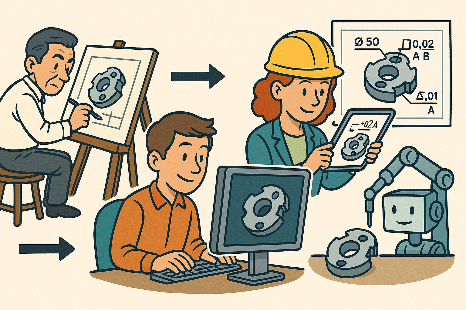
Factories and jobsites increasingly rely on precise coordination between digital models and field execution, yet the last inch remains stubbornly error-prone. With commodity depth sensors, high-quality mobile cameras, and head-mounted displays now ubiquitous, **real-time camera feeds with AR overlays** can turn that last inch into a measurable, repeatable, and auditable process. Instead of waiting for downstream inspections or chasing nonconformances after installation, teams can validate intent at the moment of action, catching misalignments when they’re still reversible. The result is a tangible step change: **earlier deviation detection**, accelerated sign-off, fewer rework hours, and continuous quality data that sharpens both design and operations over time.
Adoption hinges on engineering rigor. This practice isn’t about flashy demos; it’s about a disciplined pipeline where photons become pose, pose becomes overlay, and overlay becomes a verdict tied to tolerances. Achieving that pipeline at production scale requires a clear set of use cases with measurable KPIs, robust calibration and **drift-bounded alignment**, low-latency edge compute, semantically rich models, and tight integration to PLM/MES for provenance and traceability. In the following sections, we focus on the practicalities: where the value shows up, how the end-to-end technical stack works, and how to architect systems that survive the messy realities of shop floors and sites. The aim is to provide a blueprint that leaders, engineers, and operators can use tomorrow: start small, prove the loop, and then systematically widen coverage until AR verification becomes an unremarkable—yet indispensable—part of everyday production.
Use cases and value proposition
Layout verification
Before anchors are drilled or utilities are pulled, AR-enabled layout checks can de-risk decisions that would otherwise lock in expensive mistakes. A calibrated mobile device or HMD can project footprints of machines, guards, and fixtures directly onto the floor, while rendering keep-out zones and minimum aisle widths specified by safety policies. Operators can walk the space and perform **rapid green‑tag/red‑tag checks** that verify clearances and access envelopes in seconds rather than hours. The overlay can snap to edges of floor markings or control points, immediately flagging when a pedestal base intrudes on a path or when a pallet staging zone violates egress width requirements. Because overlays are data-bound, the system can also document pass/fail with images, poses, and timestamped user IDs for downstream approval flows.
Beyond confirmation, layout verification informs optimization. If a conveyor elbow regularly collides with cart turning radii in the AR view, planners can test alternative configurations virtually in situ. Some practical tactics include:
- Load the latest cell variant and display equipment footprints with configurable transparency to reveal underlying floor features.
- Render aisle widths and safety zones as color-coded bands that transition to red when a threshold is crossed.
- Use snap-to-edges to align overlays to chalk lines or existing machinery; enforce tolerances with **tolerance gating** that blocks sign-off if offsets exceed limits.
- Capture an audit packet (photos, overlay state, and measured offsets) for each zone, so approvals are traceable.
Most critically, green-tag/red-tag gating right at the point of installation short-circuits the typical discovery of layout violations days later, freeing rigging teams to proceed with confidence and reducing idle time for downstream trades.
Assembly verification
AR-guided assembly can overlay each subassembly, hardware type, and fastener location, converting tribal knowledge into a **step-by-step, tolerance-aware procedure**. At each step, the system projects the geometry of the part to be installed and highlights mating surfaces and datum features that drive alignment. The operator sees callouts of fastener spec (size, grade, finish), count, and **torque sequences**; as torque data streams from smart tools, the recipe advances only when all targets hit their ranges. When routing harnesses or pipes, bend radii and **keep‑out volumes** visualize limits that are hard to intuit from 2D prints; the overlay will flag a harness that exceeds minimum bend radius or a hose that crosses a hot-surface exclusion zone.
Assembly verification is most powerful when it fuses perception and procedure. Techniques that improve outcomes include:
- Render ghosted geometry for upcoming steps and edge-highlight the exact features to engage now, reducing cognitive load.
- Project thread-start cues, washer orientation, and torque sequence numbers; gate progression on empirical checks (e.g., pattern completion from vision or captured torque curves).
- Use live depth to ensure seating: ICP/point-to-plane compares confirm that a bracket is flush within tolerance before allowing fasteners to be tightened.
- Detect feature presence (labels, clips, clamps) with learned detectors and flag omissions in real time.
By turning instructions into an interactive overlay, the system both guides novices and standardizes expert behavior, lifting **first-pass yield** while reducing deviations that typically surface only at end-of-line.
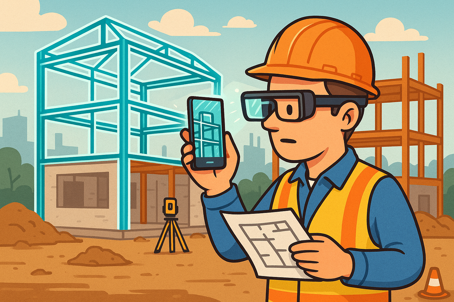
As-built vs. design conformance in AEC/industrial facilities
On jobsites and in plants, the variability of field conditions makes as-built verification critical. AR views of BIM layers (structural, architectural, MEP) can be fused with live depth to surface clashes that might not have been apparent in preconstruction coordination. When an MEP run goes in, installers can see the intended path, slope, and clearances; the system computes a **deviation heatmap** between the scan (point cloud) and the CAD shell, highlighting segments that exceed permissible offsets. For prefabricated modules, on-site **fit checks before lift‑in** reveal whether embed plates, penetrations, or stubs are within the envelope for a clean set.
Practical behaviors that increase confidence include:
- Live clash indicators between the active discipline and others, with color-coded severities and recommended adjustments.
- Snap-to-edges on slab corners or control points from a total station to anchor overlays across large spans.
- Per-run conformance reports: segment length, saddle spacing, hanger offsets, slope verification for drains, and valve orientations.
- Task-aware occlusion so the overlay hides behind real ducts or pipes, maintaining depth cues in complex plenum spaces.
When the field team can verify within minutes that a run conforms—and automatically capture the evidence—the cascade effects are dramatic: fewer RFIs, fewer rework cycles, and tighter coordination windows across trades, all flowing from a shared, visual source of truth on site.
Quality, compliance, remote support, and ROI
Quality organizations gain leverage when **CAD‑to‑reality deviation maps** connect directly to MBD/GD&T. Instead of a binary “looks good,” overlays encode datums and tolerance zones, producing signed distance fields that quantify how surfaces deviate. Per-feature tolerances drive pass/fail so inspectors don’t need to interpret ambiguous gray areas. Meanwhile, automated photo/video capture with pose and overlay state produces defensible evidence for sign-off and audits. When a nonconformance appears, remote experts can join a live feed, annotate directly on the operator’s view, and add step overlays that local staff can execute—compressing response times and reducing the need for travel.
Return on investment becomes visible once teams baseline and track the right KPIs. Common metrics include:
- First-pass yield: percentage of assemblies or runs accepted without rework or re-inspection.
- Rework hours: labor saved through earlier detection and on-the-spot corrective guidance.
- Time-to-detect deviation: latency from action to alert, ideally measured in seconds.
- Deviation magnitude distribution: shift toward smaller, correctable variances.
- NCR rate: reduction in nonconformance reports filed per unit of output.
- Audit cycle time: faster evidence compilation and approval loops.
Because the system logs each verdict with user, time, model revision, and tolerance rule, compliance shifts from periodic sampling to continuous assurance. Combined with expert-in-the-loop AR assistance, organizations see faster onboarding, standardized execution, and a clear data trail—converting quality from cost center to capability.
End-to-end technical pipeline: from photons to verdicts
Sensor stack and timebase
Reliable verification starts with sensors that see the scene consistently and clocks that agree about when frames were captured. For visuals, options span global-shutter RGB cameras that freeze motion, stereo pairs for passive depth, active ToF/LiDAR for robust geometry, and mobile stacks like ARKit/ARCore or HMDs that combine visual-inertial odometry with evolving depth APIs. Choice depends on texture, lighting, and the mobility of the task: fixed cameras for stable stations, mobile devices for walk-arounds, HMDs for hands-free assembly. Equally important is the **timebase**: PTP/IEEE 1588 provides sub-millisecond sync across a cell; NTP can suffice if it includes drift correction and per-device jitter characterization. Every frame must carry a high-fidelity timestamp plus exposure and gain metadata for downstream algorithms.
Selection and configuration heuristics that pay off include:
- Use global-shutter sensors for fast-moving tools or parts; reserve rolling shutters for slower, well-lit scenes with deblurring.
- Pair RGB with depth (stereo or active) when verification depends on precise surface alignment or occlusion.
- Log per-frame metadata (exposure, white balance, temperature) to allow robust pose and photometric residual calculations.
- Calibrate exposure controls and HDR brackets to maintain texture detail on reflective or dark materials.
With a synchronized, metadata-rich stream, later stages—tracking, alignment, and verification—have the deterministic substrate they need to turn images into trustworthy measurements.
Calibration and world alignment
Great overlays begin with accurate intrinsics and repeatable extrinsics. Intrinsic calibration—via checkerboard, Charuco, or AprilTag patterns—yields focal length, principal point, and distortion coefficients per lens; profiles should be versioned per unit and temperature-compensated when precision matters. For extrinsics, solve PnP using fiducials or register directly to CAD features by matching edges and corners. Large spaces often benefit from total station control points to anchor the world frame. When cameras ride on robots or end-effectors, perform hand–eye calibration to relate camera-to-tool, then run multi-camera bundle adjustment to minimize reprojection error across the rig. To survive shifts and days, fuse VIO with UWB beacons or RTK GNSS to maintain **drift‑bounded alignment**, especially across long traversals.
Best practices that reduce surprise:
- Schedule periodic calibration checks and surface a “calibration drift” score in the operator UI; block verification when confidence drops.
- Persist anchors in a map that includes visual descriptors and range constraints; support relocalization within seconds after occlusions.
- Combine fiducial-based bootstrapping with CAD-feature refinement so overlays “snap” to the actual object rather than tags alone.
- Record all reference frames and transforms in a graph (e.g., ROS 2 tf) to avoid silent frame mismatches.
Alignment quality is the fulcrum: if reference frames are sloppy, no algorithm downstream can produce credible verdicts. Treat calibration as a monitored, auditable asset, not a one-time setup chore.
Model preparation and semantics
Raw CAD is rarely AR-ready. Tessellation pipelines convert precise NURBS/B-rep into efficient triangle meshes with appropriate edge preservation, normals, and Levels of Detail (LOD). Use open scene formats like USD/USDZ or glTF, keeping units and axes normalized and maintaining separate coordinate frames per subassembly and per fastener group. Reduce geometric weight where fidelity doesn’t affect verification while retaining sharp features that drive pose and visibility. The key enabler is semantics: tag parts with function (e.g., “frame,” “guard,” “harness”), inspection regions, datum schemes, tolerance zones, and fastener specs, and link those tags to PLM part IDs and MBD.
Practical content authoring guidance:
- Layer inspection semantics in USD so variants (e.g., station A vs. B) can inherit a core model yet override tolerances or tool contexts.
- Define coordinate frames on critical faces, hole patterns, and mating features to simplify real-time registration.
- Chunk complex models into logical recipes: subassemblies, hardware sets, and routings, each with explicit pass/fail rules.
- Validate unit consistency and metadata schemas at import; reject models with ambiguous axes or missing IDs.
Well-prepared models become executable specifications: they don’t just draw; they tell the system what to check, where, and within what tolerance—turning geometry into a ruleset.
Tracking, scene understanding, overlay, and rendering fidelity
Pose is the oxygen of AR verification. Visual SLAM provides continuous tracking with loop closures and relocalization, while markers (fiducials or AprilTags) can bootstrap quickly in sparse scenes. Model-based pose via ICP/point-to-plane on live depth refines alignment where geometry dominates over texture. Maintaining robustness requires exposure control, white balance locks, HDR fusion on high-contrast materials, and deblurring for operator motion. Once pose is stable, overlays must respect physics: depth-based occlusion prevents virtual parts from floating through real steel; shadowing and edge-highlighting preserve depth cues; X-ray or ghost modes can expose hidden features without overwhelming the view. For headsets, the **motion‑to‑photon** budget should land below 50–80 ms, with prediction and jitter smoothing to keep overlays “nailed” to the world.
Tuning tips that matter in production:
- Use confidence-weighted sensor fusion, discounting frames with high blur or overexposure.
- Enable depth occlusion even with pre-scanned static meshes; live depth helps when the scene changes.
- Provide a quick “snap-to-edges” gesture to refine registration to the nearest sharp contour.
- Throttle visual effects under poor lighting; prioritize alignment fidelity over rendering flair.
Great rendering isn’t cosmetic—it's a measurement aid. When overlays read clearly and respect depth, operators trust them and the verification loop stabilizes.
Verification algorithms, feedback, and evidence
Verification reduces to comparing what is to what should be, then deciding with quantified confidence. In 2D–3D space, photometric residuals and edge distance maps test whether reprojected model edges align with image gradients; keypoint reprojection error checks known features (e.g., hole centers). In 3D, compare live depth or point clouds against CAD shells to produce signed distances and **deviation heatmaps**; aggregate by inspection region and gate each against MBD tolerances. Learned detectors confirm feature presence—fasteners, labels, clamps—while geometry hashing helps identify components even with partial views. Wrap this in sequence logic: a state machine advances only when the current step passes, preventing cascading errors. Operator feedback should be concise and actionable: pass/fail callouts with confidence, deviation vectors, and a **next‑best action** proposal.
Operationalizing the verdict:
- Set per-region acceptance thresholds; apply **tolerance gating** to block progression until rework or escalation.
- Attach evidence automatically: raw frames, computed pose, alignment scores, and the mesh/point-cloud snapshots used for the check.
- Write immutable audit logs with timestamps, user IDs, and model revision hashes; store only what policy allows.
- Expose a UI affordance to request expert review; include live annotations anchored in world coordinates.
When the system ties every verdict to artifacts and provenance, sign-off becomes both faster and more defensible, while failure modes turn into training data that strengthens future detection.
Software architecture and integration patterns
Compute placement and streaming
Verification is latency-sensitive, so computation generally lands at the edge, with the cloud aggregating results and retraining models. An **edge‑first** design keeps pose tracking, ICP, and gating local, avoiding network round-trips for interactive loops; if the connection drops, the cell still works and syncs later. For streaming, fixed cameras pair well with GStreamer/RTSP pipelines; mobile devices benefit from WebRTC’s NAT traversal and adaptive bitrate; inside the cell, ROS 2 provides resilient pub/sub for sensor, pose, and verdict topics. Hardware acceleration matters: CUDA on NVIDIA, Metal on Apple Silicon, and Vulkan compute across vendors; depth inference and lightweight detectors can run on edge TPUs or NPUs with quantized/compiled models.
Architectural guardrails:
- Budget end-to-end latency per pathway: camera → pose → overlay → verdict under 80 ms for HMD, and under 150 ms for handhelds.
- Isolate real-time loops on dedicated cores/GPUs; send summarizations to the cloud asynchronously.
- Use congestion-aware streaming; drop non-critical frames rather than stalling the main loop.
- Implement local failover storage so audit artifacts survive network outages.
With these foundations, the system remains responsive on the floor while still feeding the enterprise data backbone that turns local checks into global insight.
Authoring and automation
Authoring should feel like specifying intent, not writing code. Low-code verification recipes declare “checks” bound to model semantics: region-of-interest, target feature set, tolerance rules, and gating logic. In a USD scene graph, recipe layers can swap variants (e.g., model revision, optional tools) without duplicating content; per-station overlays and tool contexts select the right view and torque curves. Scriptable APIs connect to MES/PLM: “start job” fetches the relevant revision and recipe, while “post results” writes verdicts and artifacts back to the quality system.
A lightweight example of a declarative check:
- Target: Subassembly “LiftGate_HingeLeft” with datum scheme {A,B,C}; InspectionRegion = “HingeSeatTop.”
- Alignment: Model-based pose via point-to-plane ICP on depth; min inliers 85%; max RMSE 0.8 mm.
- Rule: Surface deviation ≤ 1.0 mm p95, ≤ 1.5 mm max; fastener presence count = 6 with torque ≥ 22 N·m.
- Gating: Advance when both rules pass; else prompt rework with deviation vector visualization.
By capturing checks in data, teams enable reuse, review, and simulation. Recipes move with the model through revision control, so everyone—from engineering to operations—executes the same living specification.
Digital thread and data management
To make verification trustworthy at scale, the digital thread must preserve geometry, semantics, and evidence across revisions. Versioned CAD and MBD (STEP AP242, USD) ensure rich geometry and tolerances survive handoffs. Each workstation or cell binds a configuration to a specific revision and recipe hash, preventing silent drift. For computer vision, manage datasets and models with DVC or MLflow, and augment scarce edge cases with synthetic data rendered from CAD plus domain randomization (materials, lighting, occlusions). Event logs pipe verdicts and artifacts into quality systems, building a longitudinal record of process capability.
Traceability essentials:
- Maintain lineage from camera frame → pose → verdict → sign‑off, with cryptographic hashes for each artifact.
- Encode tolerance rules and recipe versions in the evidence packet; never store raw images without policy checks.
- Provide APIs for auditors to query by part ID, time window, and station, returning both overlays and raw metrics.
- Automate dataset refresh when designs change: regenerate synthetic scenes that reflect new geometries or materials.
With a robust data backbone, the organization turns daily work into a growing corpus for continuous improvement, enabling analytics that spot systemic drifts and design tweaks that preempt recurring deviations.
Security, reliability, UX, and known pitfalls
Production environments demand strong security and high availability. On-prem deployment keeps sensitive geometry local; end-to-end encryption protects streams and artifacts; selective redaction/watermarking and role-based access ensure only necessary detail reaches each persona. **Tamper‑evident logs** and retention policies aligned to regulation keep audits clean. Reliability means monitoring the health of the sensing and alignment stack: surface calibration drift alerts, **anchor quality scores**, and lighting diagnostics that tell operators why confidence is dropping and what to fix (e.g., reduce glare, add task lighting). Human factors close the loop: occlusion-aware callouts, progressive disclosure that avoids clutter, and hands-free voice/gesture on HMDs to keep attention on the workpiece.
Known pitfalls and practical mitigations:
- Challenging surfaces/lighting: add polarized lighting, HDR brackets, or matte sprays for extreme glare; use cross-line lasers to reinforce edges for registration.
- Dynamic scenes: predictive tracking with IMU fusion reduces jitter; maintain anchor graphs that favor stable references; gate verification by confidence.
- Change churn: when a model revision lands, show **design delta overlays** and force relocalization; block legacy recipes until revalidated.
- Privacy boundaries: blur faces and redact whiteboards in captures; separate operator analytics from personally identifiable information.
Treat security and UX as first-class citizens alongside algorithms. A trustworthy, explainable, and ergonomic system sustains adoption long after the pilot glow fades.
Conclusion
Conclusion and roadmap
AR verification closes the **last‑inch gap** between digital intent and physical execution. By fusing calibrated sensors, robust alignment, semantically rich models, and real-time overlays, teams achieve **earlier deviation detection**, faster sign-off, and **continuous quality data** that compounds. Success depends on discipline: tight motion-to-photon budgets at the edge, persistent anchors with bounded drift, recipes that bind tolerances to geometry, and integrations that thread each verdict into PLM/MES with defensible evidence. The organizational move is incremental: don’t boil the ocean—pick a stable use case and iterate in the real lighting, motion, and clutter of the shop or site.
A pragmatic way to start:
- Choose a focused scenario (e.g., fixture layout or a single subassembly step) with clear pass/fail criteria.
- Stand up an edge node with one calibrated camera or HMD; define 3–5 checks tied to MBD tolerances.
- Instrument lighting and anchors; track KPIs such as first-pass yield, time-to-detect, and NCR rate from day one.
- Integrate minimally with MES/PLM: fetch the right revision, post verdicts and artifacts, and log provenance.
- Iterate weekly on UX and thresholds; expand coverage only after the initial loop is stable.
Looking forward, the roadmap is rich and actionable:
- Sensor fusion: VIO + UWB/RTK + depth for centimeter-stable anchors across shifts and after occlusions.
- Semantic SLAM: structure-aware relocalization that auto-anchors on recognized features and labeled geometry.
- Zero-shot checkers: foundation models trained on synthetic renderings that generalize to new parts and finishes with minimal tuning.
- Generative work instructions: overlays conditioned on live scene context, operator behavior, and tool telemetry to personalize guidance.
- Closed-loop control: feed deviations to robots or smart tooling for automatic corrections and to procurement for as-built traceability.
The direction is clear: make verification ambient. As sensors, models, and compute converge, the most effective factories and jobsites will treat AR checks as everyday instrumentation—the same way we take torque wrenches or laser levels for granted—quietly elevating quality, safety, and speed at scale.
Also in Design News