Your Cart is Empty
Customer Testimonials
-
"Great customer service. The folks at Novedge were super helpful in navigating a somewhat complicated order including software upgrades and serial numbers in various stages of inactivity. They were friendly and helpful throughout the process.."
Ruben Ruckmark
"Quick & very helpful. We have been using Novedge for years and are very happy with their quick service when we need to make a purchase and excellent support resolving any issues."
Will Woodson
"Scott is the best. He reminds me about subscriptions dates, guides me in the correct direction for updates. He always responds promptly to me. He is literally the reason I continue to work with Novedge and will do so in the future."
Edward Mchugh
"Calvin Lok is “the man”. After my purchase of Sketchup 2021, he called me and provided step-by-step instructions to ease me through difficulties I was having with the setup of my new software."
Mike Borzage
Novedge Webinar #108: Creating & Editing Site Models in Vectorworks – Q&A with Geoff McBeath
April 02, 2014 14 min read
We partnered up with the founder of Resolve Software, Geoff McBeath, for our latest webinar on Vectorworks. As it often happens with great webinars, there were quite a few questions left unanswered during the broadcast. Geoff took the time to send us all the missing answers, read them below.
Q: How much of what you have done for today's presentation is available in Vectorworks Architect?
A: I believe the only things I used in the presentation that are not available within Vectorworks Architect are the Create Retaining Wall Site Modifier command, and some Landmark plants shown in the final file. The Retaining Wall Site Modifier is the one I used to cut out around the building foundation. There are a few other commands and tools exclusive to Landmark and Designer. Most notable is the Grade Tool, which lets you draw an arrow on the site model which will alternately tell you the existing grade or become a modifier and create a new grade. For both of these things, there are some workarounds you can use. See the answers to the later questions for an example.
If I was an architect who was going to commit to 3D design and use site modeling regularly, trading up to Vectorworks Designer makes sense, both for these tools and for Landmark's Plant object. If you own Architect now and are just testing the waters with site modeling, I'd go with the workarounds the first time through, and see how you make out. But my feeling is that by the time you've used the extra capabilities of Designer on a couple of jobs, you've probably paid for the additional costs in time saved.
Q: Can one use subtract solids?
A: Assuming you mean, "Can I just cut away parts of the site model with the Subtract Solids command?", the answer is technically yes, but it's not a good idea in the long run. As soon as you do this, you no longer have a Site Model object—it won't have a separate 2D graphic display, just a wireframe view: you couldn't easily add more site modifiers, you couldn't calculate cut and fill, you couldn't use Send to Surface in order to put plants, symbols, property lines at the correct height…and the list goes on. With all of that said, you may find yourself working on a relatively flat site, or one with only hard surfaces, that can be well represented just using extrudes, especially for a quick, schematic model. If that's the case, using commands like Subtract Solids makes sense.
Q: If you are creating a complex curving ramp modifier and set it at a rise of 6% will it follow the center line smoothly upwards/constant slope? All your ramps were drawn straight.
A: This is a great question, but I'm glad I didn't try to answer it during the live presentation, since the answer's a bit tricky. Your question gets right to the heart of what can and can't be done with pad modifiers. Pads are planar surfaces, so while they can be sloped in any one direction, a single modifier cannot take on the curving slope of the ramp you describe, since the direction of the slope constantly changes. I tinkered a bit with this question, and found a couple of ways to do a curved ramp. Here is what I think is the slickest way:
I created a round wall representing my curved path in plan view.

To find the 6% grade, I created a temporary arc over the center line of the wall. The Object Info Palette tells me the length of the arc.
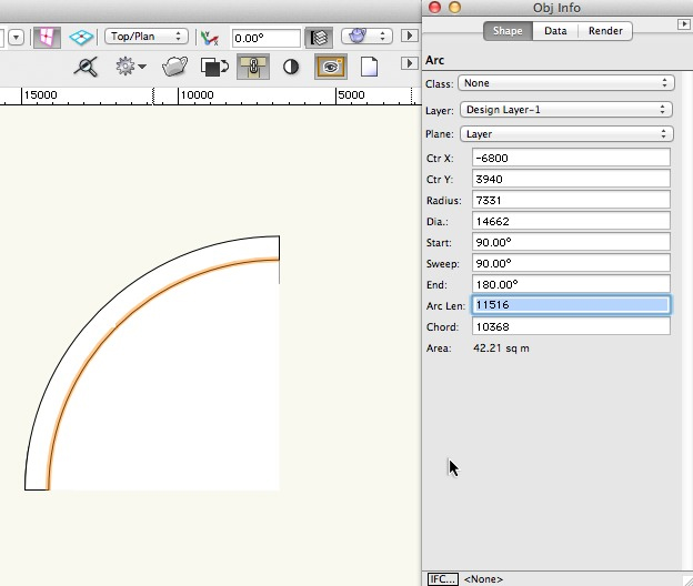
With this arc length information I can calculate that a 6% grade will mean a 691mm rise over the length of the ramp (6 x 11,516mm/100 = 691mm). I use the Reshape tool to stretch the wall end up this amount.
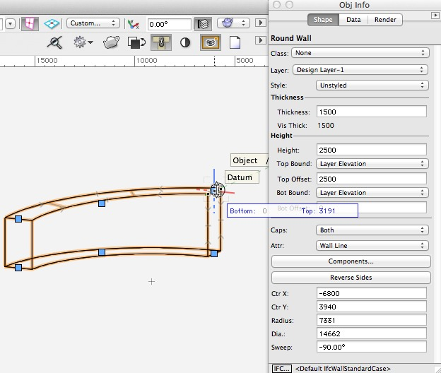
Now I use the Extract Tool to create a NURBS surface from the top of the wall.

And then Modify>Convert>Convert to 3D Polys to change the NURBS surface to a group of 3D polys.

Now put every poly in the group into the class Site-DTM-Modifier. This is the 'magic' class which is recognized by the site model, and it is created automatically by the Site Modifier Tool, so it's probably already in your file by this time. If you draw your own 3D polygons in this class, they'll automatically act as site modifiers.
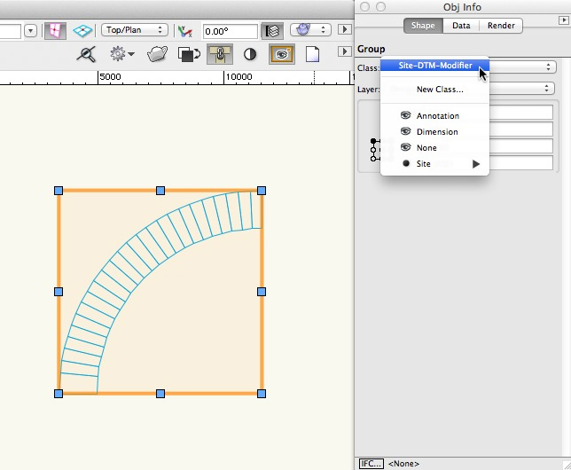
Now move the ramp modifier into place, and set its height according to whatever's needed for your design. Update the Site Model to display the proposed site.

With the addition of a Hardscape object set to act as a Texture Bed, you've now got a curved ramp with a 6% slope integrated into the site model.

I also can see a way to do this with a series of segmented pads, each one with a changing angle of slope, but it looks like more work than this method. One thing about this method though, is that it gives you no way to make a small change to the existing modifiers. If you changed your slope to 8%, the best thing to do would be to start over. I'd save all the objects made in those first steps in a separate file, so that you can quickly go back and re-create the needed 3D polys.
Q: How can you clean up the edge of your site model if survey does not extend past the lot line?
A: My typical answer to this is to make up some fake elevations and put them on the other side of the lot line. In this way, any incorrect triangulation at the edge is further out, and you can use the Site Model Crop to then trim back the edge to where it's nice and clean. Now don't get me wrong, if you're working on something in which the fine grading at the edge of the lot is critical, I'm not suggesting that you still make things up. But if what you're doing is a simple visualization, and you just need a few more points to smooth out the rough edges, it's probably fine, and something you can interpolate from looking at your site photos or visiting the site.
Q: Are the site model files from today's webinar available for the public to work on?
A: Sorry, no.
Q: If one is doing cut and fill calculations — somebody wants their landscape remodels to have lovely hills on it — and you build a model to look like what the final surface grades will be, how do you calculate the cut volumes and fill volumes?
A: Piece of cake…once the modifiers are in place, you've clicked Update, and the proposed site model is showing up, you can then click the button named Update Cut and Fill Calculations in the Object Info Palette. As seen here, you'll get total cut, total fill, and the difference. The volume units for the calculations can also be set here.

Q: Is Vectorworks able to automatically ignore for ID and description fields?
A: So I guess this question is about the import of the survey points. If those fields are present in the survey data, you need to account for them in the import format chosen, so the answer would be no, it can't automatically ignore the fields. But this isn't really an issue. What you'd normally do is bring it all in, and that data is stored with each Stake Object. If you don't want to display it, you don't need to. You can just set the Stake Objects to display only the fields you wish. But now you've got that info in the file if you need to refer to it for some reason later in the design process. See the related question below.
Q: How did you convert separate pads to a single polygon?
A: You're talking about the step in which I took all the parts of the paving and made them into one object, then converted that to a Hardscape. Actually, at that point they weren't pads, but just rectangles. Before converting anything into pads, I made a duplicate of the original rectangles on my Hardscape layer, then I simply selected them and chose right-click>Add Surface to turn them into a single polygon.
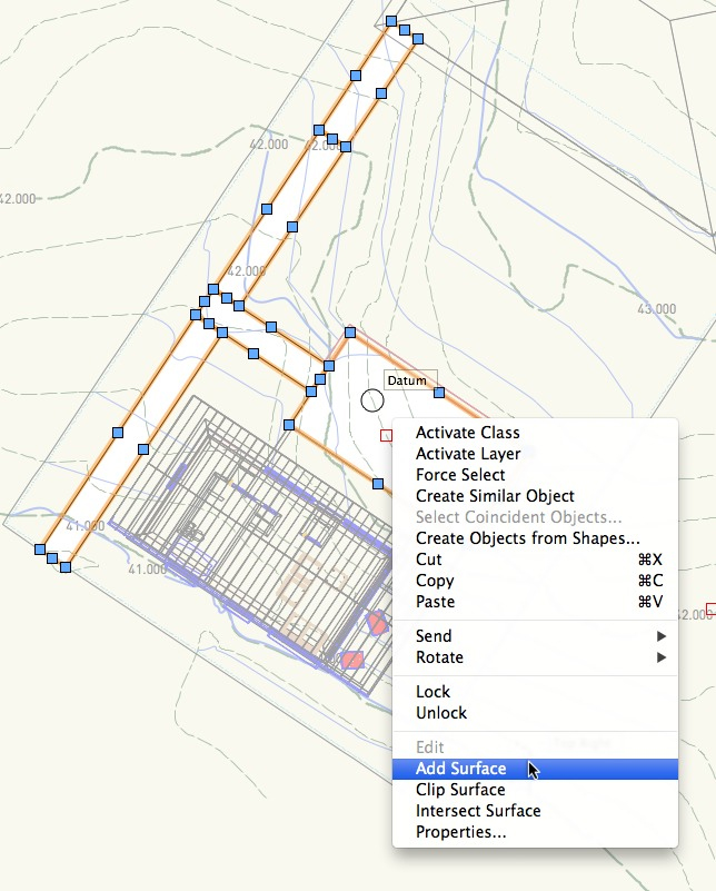
Q: How did you determine the slope of the walkways?
A: To save time during my presentation I zipped through this, just filling in the values with numbers I had already determined would work. Of course, in a real-world project you'd have a bit more calculation. For example, for the sloped walkway between the house and the patio, as seen below, I did the following:
– sidewalk from house = elev. 42.50m (already established)
– sidewalk from patio = elev. 41.80m (already established)
– difference = 0.70m
– length of walkway = ±6.0m
– perform good ol' cross-multiplication, 0.70/6.0 = x/100
– slope would need to be 11.67% (I believe I used 11.5% in my presentation)
If suitable, put values in fields for the pad modifier and you're done. If not suitable, for example if you want less slope, then lengthen ramp, shorten flat segment at the top, recalculate slopes, etc., until design and grading criteria are met.

Q: How did you set the elevation of the massing model for the house? For the property line?
A: Massing Model objects will respond to the Send to Surface command, which puts them more or less where you want them, but not perfectly. Since the terrain is sloping, the lowest corner was sitting in mid-air. But since the placement of the massing model in this project didn't need precision, just an approximate location representing the existing house, I fine-tuned it by increasing the overall height of the Massing Model, then lowered it down into the ground using Modify>Move>Move 3D until it looked about right.
For the property line, I did the following:
– select the 2D polygon from the DWG import, Duplicate, change class to None, choose Cut
– return to model file, choose Paste in Place
– with polygon still selected, choose Send to Surface
*The shape is automatically converted to a 3D polygon which drapes the surface of the site model. It is given as many vertices as needed to conform to the triangulated surface of the site model.
– use Move 3D to raise the height of the property line a few inches more (if it's exactly at the surface of the model, it won't show up clearly when you render)
Q: Why is "Site Modifiers on Layers" in Site Model setup?
A: So I guess you mean the pop-up menu highlighted below. It lets you choose which site modifiers get used when the site model is calculated. For me, it's always set to All Layers. In this way, I never risk changing site model results if I make a change to layer visibility.

Q: How is the site modified in the gaps between the pads? I've had sharp 'spikes' in my model between pads.
A: Hmm, don't know. It's hard to say without seeing the file. One possibility is that you had a Grade Limits modifier around each pad. If this was the case, there would be no regrading between the pads, and it could result in those spikes.
Q: How should building layers relate in elevation to terrain model origin elevation, if they are halfway up the slope; and is it a problem if building is set far from zero elevation, e.g. +500'?
A: This is a judgment call—it can be done more than one way. If you will use real-world elevations in your architectural drawings when calling out elevations for floors, roof, etc., then I would set the layer elevations to height above sea level, and in this way your building and site model will automatically correspond. I did this in the example model in my presentation, as you can see below. Heights here are in meters.
 And by the way, the Elevation Benchmark tool will then automatically pick up those real-world elevations when you annotate your section.
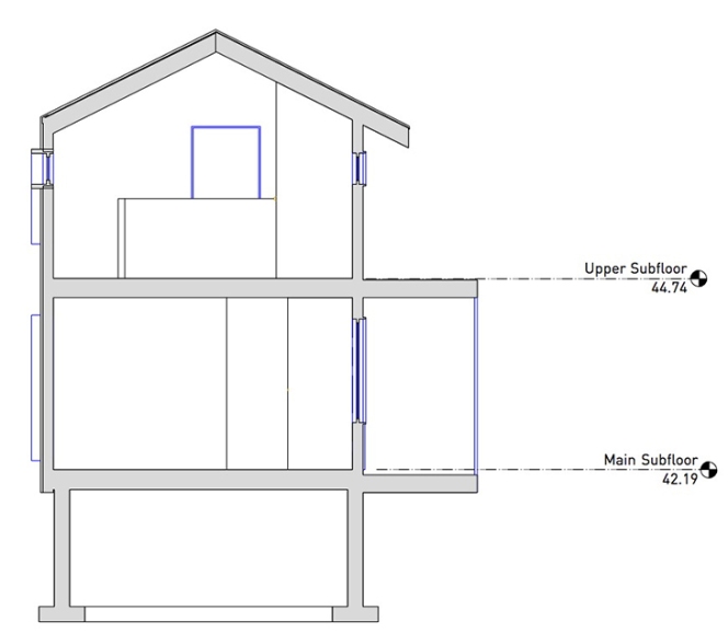
But if you follow the convention of setting a project datum (e.g. main floor subfloor = 0), then you could set your layer Z (or Story Elevation) to zero, and when you bring the referenced viewport of the model into the site model, you make a height adjustment, bringing the building from zero up to its real-world elevation.
Q: Will there be supporting notes for this webinar?
A: Sorry, I don't have supporting notes. The presentation was not created as a step-by-step tutorial, but as a demonstration that would spur you to try out the techniques on your own projects. I encourage you to watch the presentation again if needed, but then dive in on your own project.
Q: Would you ask for the text file for just the the level (elevation data) or the whole survey?
A: I'm not sure I understand the distinction you're making between these two. I would simply ask for a text file of the survey. Your experience may differ, but from what I've seen, you're going to get whatever they already have, and they're not going to make many (or any) adjustments to the file that came out of their machine. The request usually yields something very similar to what I demonstrated, but there are variations in formatting, data headers, etc., and that's why previewing it in Excel is an excellent idea. It gives you an opportunity to see what you've got and to clean up any messiness in the data.
Q: It doesn't seem as though the GIS photo drawing were really necessary. If you did use it, how?
A: Fair comment, I didn't really use it in my presentation. My goal was to show importing a georeferenced photo. My assumption is that you might use the photo to inform your design process and presentation. If I'd had more time I might've shown a site plan with the photo in the background, providing context of the surrounding area. The key thing is that if you have the photo, you shouldn't be nudging it left and right until it kinda aligns, you should be able to use the provided .tfw file to bring it in to the correct spot.
Q: I always thought the origin had to be 0-0. Not true?
A: Vectorworks files have two origins, an internal origin which does not change, and a user origin which can be reset by using Tools>Set Origin. The attention I've given to setting the user-defined origin when setting up files and importing files is based on the greatly increased number of georeferenced files out there today. The process I described in the presentation is to import the DWG file so it's centered over the internal origin, and then reset the user origin so that the coordinates of any object match what they were in the original file. In this way, you're still working close to internal 0-0 and won't get any geometric problems in the file that come with extreme distances from origin. So you might say that the origin is still at 0-0, but we've changed the numbers on the rulers to match what they were in Autocad or the GIS program that the data came from.
It's also important to say that I'm not trying to make your project setup more complicated than it needs to be. If your drawings start and end with you, preserving the X, Y equivalents of latitude and longitude really might not be needed. In that case, feel free to ignore these elaborate steps. But if you need to send your files back to others throughout the process, and they expect the X, Y coordinates to stay the same, you'll have a problem if you don't follow these methods.
Q: What happens to site model within cement wall?
A: The site model elevation differences between the grades inside and outside the wall are taken up in the wall's thickness. See the more detailed explanation below.
Q: What are .tin files?
A: It is a file format used in GIS for representing a site. Vectorworks doesn't use it directly, and though I know about it, I've never personally seen it used by Vectorworks users. It might be possible, but if I was given one, I think that before tinkering with it I'd ask if they can resend in one to the text formats (e.g. .txt or .csv) that are more readily imported into Vectorworks.
Q: What is the optimum minimum distance between two pads?
A: It doesn't really matter, as long as they don't touch or overlap. Although there are many places in CAD and modeling that need you to have everything snapped together perfectly, this isn't one of them. What matters is that you coax the site model into the shape you want.
Q: When you offset the pad what was the distance you used?
A: I think I offset my original rectangles by 10cm (4"). As explained above, there's nothing magical about that number, it was a bit arbitrary.
Q: Where did you get the twf format?
A: The .tfw file came with this photo because the photo was part of a set of air photos covering the city, and part of the GIS data used by the local government. You'll typically see it when you're getting air photos from government sources or from companies that sell high-quality photos.
Q: Is there a way to display Existing and Proposed contours/grade in a _live_ site section? (I am aware of making a non-live one via AEC > Terrain… > Site Model Section).
A: Sort of…I did a test of this just now and see a fairly workable method. I did the following:
– create a section viewport of the existing site, put it on a design layer
– in the Object Info palette, uncheck Display Objects Beyond View Plane so that you see only a profile at the cut line
– convert the viewport to a Group
– return to the model, update the site model to display the proposed site
– make a new section viewport showing the proposed site, put it on the same design layer
– overlay the two shapes, change the existing site's color, line type, as needed to distinguish it from proposed
So this is cheating a little bit…the existing site is not really live. But since the existing site doesn't change, I think it's an acceptable cheat.


Q: Regarding the "descriptions" of each stake object… Where does that info go and how can it be seen/used after import?
A: It is contained within the stake object itself. If you want to see it, you can change any or all stake objects' Label Reference setting, as seen here.
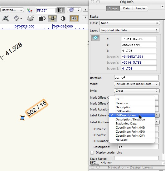
Alternately, you could make a database report and display it within a Vectorworks worksheet. Use Tools>Reports>Create Report.

Q: It would be great to see the VW Architect workaround for the retaining wall site modifier (as part of the blog post.)
A: Start by making a rectangle the size of the excavation. Here it is set to the inside of the walls.
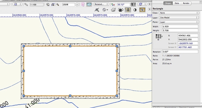
Use AEC>Create Objects from Shapes, and turn it into a Site Modifier.

It should be turned into a Pad, and choose Apply To the Proposed model. Set the elevation to the height that represents the bottom of your excavation.

Now set some 3D loci or Stake Objects along the corners of the walls, and along any other critical points where you wish the finished grading against the foundation to run.

Use the 3D Polygon Tool, and just connect the dots. Make sure you're drawing in the class named Site-DTM-Modifier. If you draw your own 3D polygons in this class, they'll automatically act as site modifiers.
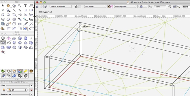
Now update your site model and you should see the results. The blue 3D polys become your finished grading along the outside edge of the foundation. The pad becomes the bottom of the excavation.

Most of the grading takes place in between the outside and inside of the walls. In truth, you could set the pad to be just a hair smaller than the outside face of the walls and it would work fine, just as long as the modifiers don't overlap or touch. I just drew it to the inside because it's easy.

Q: Regarding a site model “snapshot”… when is it useful to use one? And does a site model snapshot actually update when you edit the original, editable site (because it appears that it does) or is this simply a display hiccup? (This would of course be to compare existing vs proposed to get a sense of cut and fill requirements.)
A: Right, I know about hiccups with the Site Model Snapshot, as I had a couple of them when I was trying it out in my presentation. I think it's useful to use a snapshot when you want to look at the impact of some regrading. It's a way of having two views at once. On the left I've got contours and my site modifiers. On the right I have a snapshot with color-coded slopes. I've moved the snapshot off to the side, but I'd never move my actual site model, as too much needs to stay aligned with site model. For example, the blue areas represent less than 2% slope, so I might have pooling water in a couple of these areas. I could make adjustments on the site model, update it, then see the results on the snapshot. Back to the hiccups…I do notice that on my computer, the snapshot doesn't always appear to refresh itself after a change to the site model. I think this is a video card or general display glitch, as zooming in or out slightly forces the screen to redraw, and the snapshot changes then appear.

To register for future Novedge Webinars, click here. To get your own copy of Vectorworks in the United States, visit our website at novedge.com.
If you are reading this from Canada, get your copy of Vectorworks from Resolve.
Also in NOVEDGE Blog
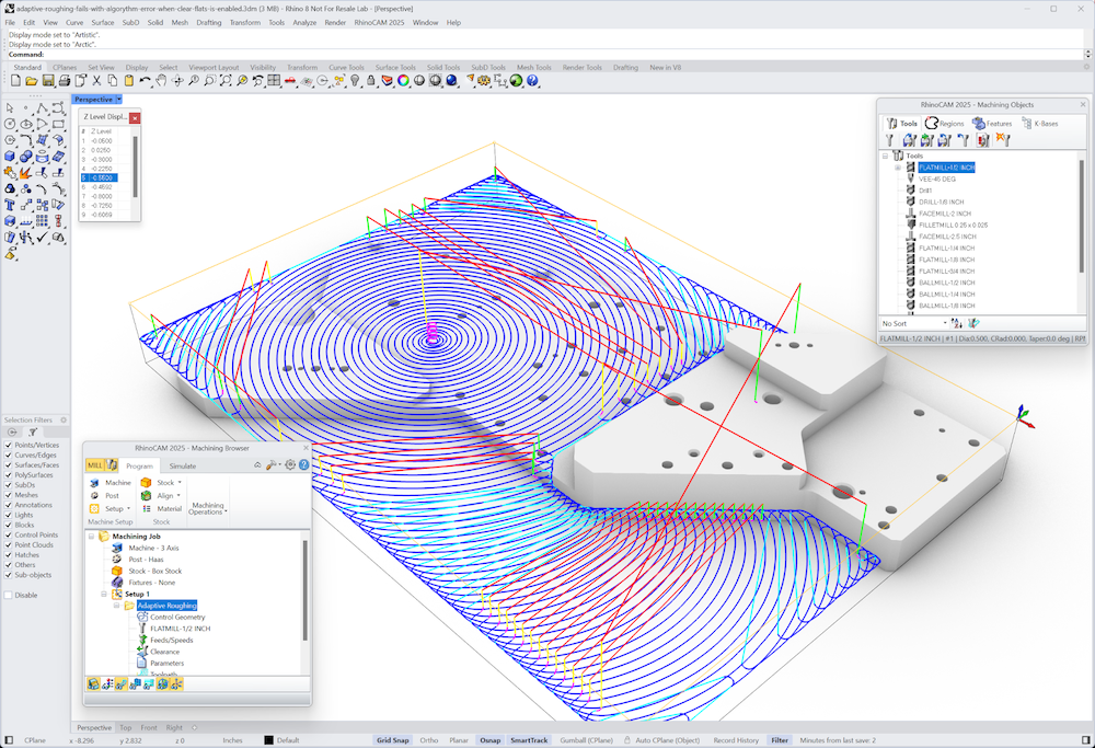
MecSoft Unveils RhinoCAM 2025 and VisualCAD/CAM 2025 with Enhanced Features
March 08, 2025 5 min read
Read More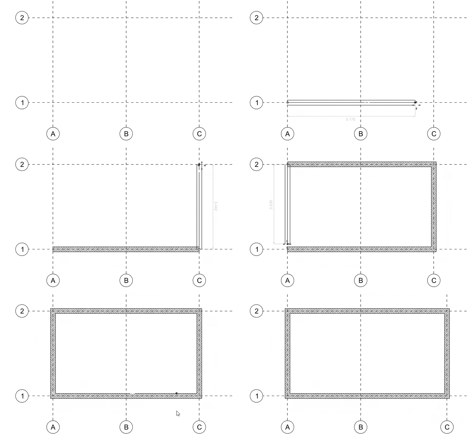
Maximize Your Architectural Workflow with VisualARQ 3's New Guides Feature
January 30, 2025 5 min read
Read MoreSubscribe
Sign up to get the latest on sales, new releases and more …


