
Your Cart is Empty


Topology Optimization as a Production-Ready Engineering Deliverable
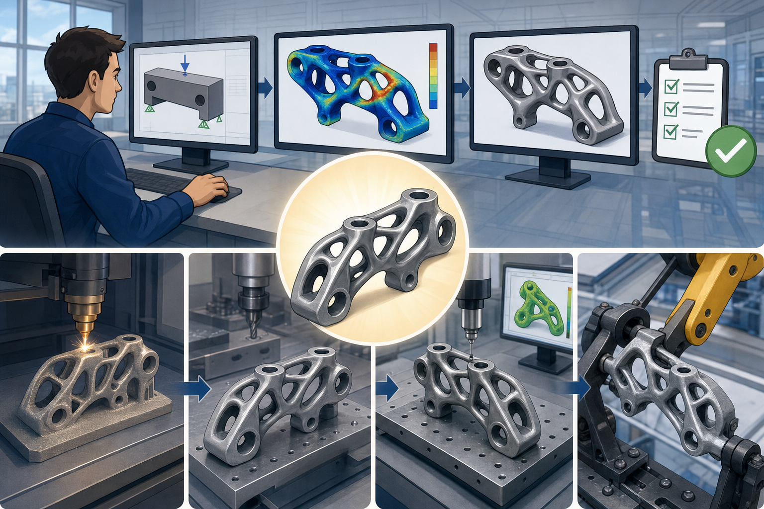


Topology Optimization Is Becoming an Engineering Deliverable
From visual inspiration to accountable geometry
Topology optimization has moved through a remarkable transition. For many years, its most visible contribution to design software was the generation of dramatic, bone-like forms that helped designers imagine lighter components. These outputs were useful because they challenged conventional thinking, especially in mechanical brackets, aerospace structures, robotic arms, medical devices, and high-performance architectural nodes. Yet many of those results were closer to visual prompts than engineering deliverables. The optimized form often required extensive manual remodeling before it could be analyzed, dimensioned, manufactured, inspected, or released into a controlled product development workflow. Today, that expectation is changing. Teams no longer want optimization tools that simply suggest where material could be removed; they want geometry that can survive the entire downstream process. A useful result must respect **real engineering constraints**, produce clean CAD-ready features, support repeatable manufacturing, and remain traceable through validation, documentation, and lifecycle management. In this new environment, topology optimization is less about producing surprising shapes and more about producing reliable decisions.
The unresolved gap in earlier workflows
Earlier optimization workflows frequently separated simulation intelligence from design practicality. An engineer would define a design space, apply loads, set constraints, run a solver, and receive a faceted density map or triangulated mesh that appeared efficient under the defined conditions. The problem emerged immediately afterward: the result was rarely a production model. Someone had to interpret the mesh, rebuild it in CAD, simplify questionable branches, thicken fragile members, add mounting features, standardize fillets, preserve clearances, and prepare the model for another round of analysis. This manual remodeling phase could erase part of the original optimization advantage because the designer was effectively translating a mathematical result into an engineering object. In some organizations, the remodeling effort was so large that topology optimization became a conceptual exploration tool rather than a routine production method. The lesson was clear: an optimized shape is not automatically an optimized product. To become useful in practice, the result must enter a loop of **CAD validation, manufacturing planning, inspection strategy, and certification evidence** without losing design intent.
What “production-ready” really means
A production-ready optimized model must satisfy a more demanding definition than simple weight reduction. It must meet strength, stiffness, fatigue, thermal, vibration, and durability targets under realistic load conditions. It must include non-negotiable functional regions such as bearing seats, fastener interfaces, sealing surfaces, datum structures, electrical clearances, assembly access, and inspection surfaces. It must also be manufacturable using the selected process, whether that process is powder bed fusion, directed energy deposition, CNC machining, casting, forging, sheet fabrication, composite layup, or injection molding. This raises deeper questions for design teams. Can optimized forms meet real engineering constraints rather than idealized simulation assumptions? How much human interpretation is still required when software proposes a shape? What separates a conceptually efficient form from a model that can move into procurement, process planning, quality control, and release management? The answer is not a single algorithm. It is a connected design process where constraints, geometry generation, simulation verification, and manufacturing knowledge are treated as one digital thread.
The Inputs That Determine Whether Optimization Is Useful
Loads, boundaries, design space, and non-design intent
The quality of a topology optimization result is largely determined before the solver begins. Loads and boundary conditions are not administrative inputs; they define the physical reality the algorithm is allowed to understand. If loads are simplified incorrectly, if constraints are over-fixed, or if contact behavior is ignored, the resulting structure may be elegant but misleading. The same is true for the design space. A generous design envelope gives the solver freedom, but if it includes areas that must remain clear for assembly, airflow, tooling, wiring, maintenance, or human access, the output becomes difficult to use. Non-design regions are equally important because they protect interfaces that must remain stable, such as bolt holes, bushings, bearing housings, alignment pins, sealing flanges, sensor mounts, and standardized connection geometry. Advanced teams treat these elements as carefully as they treat material removal targets. They define what can change, what must remain fixed, what must remain accessible, and what must maintain dimensional precision. In doing so, they shift optimization from abstract material distribution toward **constraint-driven engineering geometry**.
Critical study inputs that shape the result
A useful optimization study is not just a solver run with a weight target. It is a structured engineering definition that combines performance requirements, material behavior, manufacturing limits, safety expectations, and downstream validation needs. These inputs are usually interdependent. For example, a material with excellent strength may have anisotropic behavior in additive manufacturing, while a casting process may impose different minimum section thicknesses and draft requirements than a machined billet. Similarly, a part optimized only for peak static loading may fail to address fatigue or vibration durability. To make the process practical, design teams often formalize the inputs before the optimization stage begins. This reduces ambiguity and prevents the solver from exploiting unrealistic assumptions. The most important inputs typically include:
- Loads and boundary conditions that represent operating, transport, assembly, misuse, and service scenarios.
- Design space and non-design regions that distinguish flexible volume from protected functional geometry.
- Material properties, including elastic, plastic, fatigue, thermal, and process-dependent characteristics.
- Manufacturing constraints, such as overhang limits, tool access, draw direction, draft, minimum wall thickness, and support removal.
- Safety factors and performance targets tied to stiffness, displacement, frequency, thermal gradient, buckling, fatigue life, or cost.
When these inputs are weak, the output may still look sophisticated, but the apparent intelligence belongs more to the visualization than to the engineering method.
Material definition and the danger of idealized assumptions
Material definition is one of the most underestimated aspects of topology optimization. Many early workflows assumed homogeneous, isotropic, linearly elastic material behavior, which is acceptable for early exploration but insufficient for production intent in many industries. Additive manufacturing can introduce directional properties, residual stresses, porosity, surface roughness effects, and heat-treatment dependencies. Castings may include local variation in cooling rate, grain structure, and defect probability. Fiber-reinforced composites bring orientation-driven stiffness and failure behavior that must be considered from the earliest optimization stages. Even conventional metals require attention to fatigue, notch sensitivity, surface finish, and environmental exposure. If the optimizer treats the material as an ideal continuum while the manufacturing process produces measurable variation, the result may be overconfident. Production-ready optimization therefore requires material models that reflect service and process realities. This does not mean every study must begin with the most complex nonlinear model available. It means the design team must understand which material assumptions are acceptable at each stage and where those assumptions must be tightened before release.
Advanced Optimization Methods Are Expanding the Design Space
Multi-objective optimization for competing requirements
Real products rarely optimize around a single objective. A bracket should be light, but it may also need high stiffness, low cost, manufacturability, fatigue durability, thermal stability, and compatibility with assembly automation. A heat exchanger support may need structural integrity while allowing airflow and minimizing thermal distortion. A robotic end-effector may require low mass for acceleration, high stiffness for positional accuracy, and carefully tuned dynamic behavior to avoid vibration. **Multi-objective topology optimization** addresses these competing demands by searching for trade-offs rather than a single mathematically pure answer. Instead of asking only for minimum mass under a displacement limit, the software can evaluate stiffness-to-weight ratio, natural frequency targets, material cost, thermal conductivity paths, and process constraints together. The result is often not one final geometry but a family of viable candidates along a performance frontier. This is useful because engineering decision-making is rarely binary. A slightly heavier design may reduce machining complexity, improve inspection access, or provide a better safety margin. The best optimization workflow therefore supports comparison, not just generation.
Multiphysics optimization and coupled behavior
As design software becomes more computationally integrated, topology optimization is increasingly applied to problems involving coupled physics. Structural optimization alone may miss critical interactions with heat transfer, airflow, acoustic behavior, electromagnetic performance, or fluid pressure. In electronics housings, material placement affects stiffness, heat dissipation, shielding, and service accessibility. In turbine-related components, geometry may influence mechanical loading, thermal gradients, resonance, and cooling flow. In architectural design, an optimized node or façade element may need to balance load transfer, thermal bridging, fabrication efficiency, drainage, and installation tolerance. **Multiphysics optimization** makes these interactions visible earlier in the design process. It also raises the standard for constraint definition because each additional physical domain introduces new boundary conditions, material responses, and validation requirements. A structurally efficient shape may trap heat. A thermally efficient shape may reduce stiffness. A flow-efficient form may be difficult to inspect or impossible to machine. The power of multiphysics optimization is not that it eliminates trade-offs; rather, it exposes them while geometry is still flexible enough to be improved.
Lattice and cellular structures for additive manufacturing
Additive manufacturing has changed the conversation around topology optimization because it allows internal complexity that traditional processes cannot easily produce. Lattices, cellular structures, graded porosity, gyroid forms, and variable-density infills can create components that manage stiffness, energy absorption, heat transfer, vibration damping, and biological integration in highly localized ways. However, lattice optimization is not simply decorative infill. To be production-ready, a lattice must account for minimum strut diameter, powder removal, support strategy, surface roughness, inspection method, post-processing access, and the difference between as-designed and as-built geometry. Thin lattice members may appear efficient in simulation but become unreliable if they fall near process capability limits. Dense lattice zones may trap powder or complicate cleaning. Highly intricate internal cells may be difficult to confirm with conventional inspection methods. This makes lattice optimization one of the most powerful but also one of the most demanding areas of advanced design software. It requires a workflow where geometry generation, process simulation, build orientation, support planning, and performance validation operate together rather than as disconnected steps.
Robust optimization under uncertainty
Production environments contain uncertainty. Loads vary, materials vary, manufacturing processes vary, operators make adjustments, machines drift, surfaces wear, and assemblies accumulate tolerance stack-ups. Traditional deterministic optimization can produce a result that performs well under one exact condition but becomes vulnerable when real-world variation appears. **Robust optimization** addresses this issue by evaluating performance across ranges of uncertainty rather than a single ideal state. It may include variations in load angle, bolt preload, material modulus, printed wall thickness, surface finish, temperature, or boundary stiffness. The goal is not just to find the lightest structure, but to find a structure that remains acceptable despite realistic disturbances. This is particularly important in safety-critical products, high-cycle fatigue environments, and components manufactured close to process limits. Robust optimization also changes the meaning of efficiency. A design with slightly more material may be superior if it is less sensitive to variation, easier to inspect, and more forgiving in service. The emerging best practice is to optimize for reliable performance, not merely peak simulated performance.
Solver Quality, Meshing, and Constraints Control Geometry Usability
Why the mathematics behind the interface matters
Modern design software often hides complex numerical methods behind friendly interfaces, but topology optimization remains deeply dependent on solver quality. Algorithms differ in how they handle density distribution, stress constraints, buckling behavior, manufacturing rules, convergence, contact, nonlinearities, and local minima. A tool may produce visually appealing geometry while quietly smoothing over critical numerical limitations. For professional engineering use, the team must understand what the solver is actually optimizing and what it is approximating. Stress-constrained topology optimization, for instance, is significantly more challenging than compliance minimization because stress is local, mesh-sensitive, and prone to concentration near geometric transitions. Buckling and vibration constraints introduce further complexity because small topology changes can alter mode shapes and stability behavior. The practical question is not whether a solver can generate an organic shape. It is whether the solver can produce a result that remains meaningful when refined, re-meshed, reanalyzed, manufactured, and tested against the full set of product requirements. **Numerical credibility** is therefore a production issue, not merely a simulation preference.
Meshing strategy and the resolution of design intent
Meshing strategy strongly influences the usability of optimized geometry. A coarse mesh may suppress important load paths or create blocky forms that require heavy interpretation. A very fine mesh may reveal elegant structural features but produce geometry that is too complex for manufacturing or too expensive to convert into clean CAD. Element type, mesh quality, local refinement, and the relationship between mesh size and minimum feature size all affect the result. If the optimizer is allowed to create members smaller than the manufacturing process can reliably produce, the design may look efficient while being physically impractical. Conversely, overly restrictive minimum feature constraints can remove useful structural paths and produce conservative geometry. Mesh independence is also important. If a small change in element size produces a radically different topology, the result may not be stable enough for production decision-making. Effective teams use meshing as a design control, not just a preprocessing task. They align mesh resolution with manufacturing capability, inspection resolution, critical stress gradients, and the level of geometric detail that downstream CAD systems can manage.
Constraint definition as a creative engineering act
Constraint definition is where topology optimization becomes a design discipline rather than a black-box calculation. The designer is no longer simply shaping surfaces by hand; the designer is shaping the problem the software is allowed to solve. This changes the creative role in a profound way. A poorly constrained problem invites the optimizer to exploit freedoms that do not exist in reality. A thoughtfully constrained problem channels computational search toward practical, high-performance solutions. For example, defining draw direction for casting, tool access for machining, support minimization for additive manufacturing, or symmetry conditions for assembly can radically change the resulting form. The designer must also decide which constraints are strict and which are negotiable. A displacement limit may be fixed by function, while a mass target may be flexible if a small increase improves fatigue life or production yield. In this sense, advanced topology optimization rewards engineers who understand both physics and manufacturing. The strongest results emerge when software intelligence is paired with human judgment, selective simplification, and a clear understanding of product intent.
From Mesh Output to Clean Engineering Geometry
The persistent geometry translation problem
The gap between simulation output and clean engineering geometry remains one of the central challenges in topology optimization. Many solvers produce results as density fields or faceted meshes, which are appropriate for numerical interpretation but not ideal for detailed design release. CAD systems depend on precise surfaces, editable features, stable references, dimensions, tolerances, and associativity with assemblies and drawings. A raw mesh may contain jagged edges, uneven thickness, tiny disconnected regions, irregular curvature, and local artifacts caused by element discretization. Even if the overall load path is correct, the geometry may be unsuitable for machining paths, build preparation, inspection planning, or tolerance annotation. This is why direct use of optimized mesh output is still limited in many production environments. The output must often be reconstructed into NURBS surfaces, subdivision geometry, implicit bodies, or parametric CAD features. The difficulty is maintaining the structural logic of the optimized result while transforming it into a controlled model. Too much smoothing can weaken performance; too little can make manufacturing impractical.
Common production issues in optimized forms
Optimized shapes often reveal production challenges that are not obvious during the first simulation review. Rough mesh geometry can create small notches that amplify stress or complicate toolpath generation. Thin ribs may become impossible to cast, print, machine, or inspect reliably. Overly complex surfaces can increase programming time and reduce dimensional confidence. Smooth organic transitions may look strong but still lack clear datum structures for measurement. Internal voids may reduce weight while creating powder removal or cleaning problems. Stress concentrations may appear near protected interfaces because the optimizer concentrates load paths into narrow regions. These issues are not failures of topology optimization; they are reminders that mathematical efficiency must be reconciled with manufacturing reality. Teams evaluating optimized geometry should commonly check for:
- Rough or noisy mesh regions that need smoothing or reconstruction before CAD release.
- Stress concentrations at transitions, holes, branch intersections, and constrained interfaces.
- Overly complex surfaces that increase manufacturing cost or make tolerance control difficult.
- Difficult inspection requirements, especially for internal channels, lattices, and freeform surfaces.
- Manufacturing process limitations related to tool access, supports, draft, shrinkage, minimum sections, or fixturing.
Recognizing these issues early helps prevent optimization from becoming a late-stage remodeling burden.
Automated smoothing and surface reconstruction
Modern design software is improving the transition from optimized output to usable CAD through automated smoothing, surface reconstruction, and hybrid modeling techniques. Smoothing tools reduce faceting and remove numerical artifacts while attempting to preserve the primary load paths identified by the solver. Surface reconstruction tools convert meshes into editable forms, sometimes using subdivision surfaces for organic continuity or NURBS patches for conventional CAD operations. More advanced systems can extract recognizable engineering features from mesh-based results, such as holes, bosses, ribs, blends, planar faces, and mounting interfaces. This is important because production CAD is not only a shape container; it is a decision model. Engineers need to edit wall thickness, adjust fillets, relocate holes, define datums, control clearances, and propagate changes through assemblies. Parametric regeneration from optimized results can reduce remodeling time by transforming computational geometry into features that behave predictably. The best workflows preserve both sides of the problem: the organic efficiency of optimization and the structured editability of CAD. This balance is essential for practical adoption beyond exploratory design.
Implicit modeling and field-driven geometry
Another major development is the rise of implicit modeling and field-driven design. Unlike traditional boundary representation CAD, implicit modeling defines geometry through mathematical fields, making it well suited for complex blends, lattices, graded structures, and topology-optimized forms. This approach can handle intricate internal geometry more robustly than conventional surface patching, especially when working with additive manufacturing designs. Field-driven methods allow designers to vary lattice density according to stress, temperature, displacement, or user-defined performance zones. They can also blend solid structures into cellular regions without creating thousands of fragile surface intersections. However, implicit modeling still needs integration with engineering controls. A field-defined body must support dimensional verification, manufacturing export, simulation feedback, and change management. It must also communicate design intent to downstream stakeholders who may expect conventional CAD references. The practical value of implicit modeling is highest when it is not isolated from CAD, CAE, and CAM. It becomes powerful when it acts as a bridge between computational material placement and manufacturable geometry generation.
Manufacturing Constraints Must Be Embedded Early
Additive manufacturing constraints are more than overhang rules
Additive manufacturing is often associated with topology optimization because it can produce complex shapes that would be difficult or impossible with subtractive methods. Yet additive freedom is not unlimited. Production-ready additive designs must consider build orientation, support structures, overhang angles, residual stress, thermal distortion, powder evacuation, surface finish, minimum wall thickness, machine envelope, post-processing, and inspection. Overhang control is valuable because it can reduce support material and improve build reliability, but it is only one part of the complete constraint set. Minimum wall thickness rules prevent fragile geometry that may fail during printing, depowdering, heat treatment, or handling. Support removal access may require openings, drainage paths, or simplified regions that the optimizer would not create independently. Internal channels and lattices must be designed so trapped powder or resin can be removed reliably. Advanced software increasingly embeds these constraints inside the optimization process rather than applying them after the fact. This is a critical shift because a geometry corrected after optimization may no longer behave like the optimized result.
CNC, casting, forging, and molding constraints
Topology optimization is not limited to additive manufacturing, but non-additive processes require different rules. CNC machining demands tool access, realistic cutter radii, fixturing surfaces, setup planning, and avoidance of deep inaccessible cavities. A shape that is optimal structurally may become expensive if it requires five-axis machining with long tools, multiple setups, or excessive material removal. Casting introduces draft, parting lines, minimum section thickness, fillet requirements, shrinkage behavior, and feeding considerations. Forging requires attention to material flow, die access, flash, grain orientation, and post-forge machining allowances. Injection molding imposes wall thickness consistency, ribs, bosses, draft, sink marks, gate location, cooling behavior, and ejection strategy. When these process constraints are embedded early, topology optimization can produce results that respect the manufacturing path instead of fighting it. This does not mean the optimizer must fully automate process engineering. It means the design study should reflect enough production reality that the output is directionally manufacturable. **Manufacturing-aware optimization** is the difference between an attractive lightweight proposal and a design that can survive cost review.
Inspection and certification as design constraints
Production-ready geometry must be measurable, not merely manufacturable. Inspection requirements can significantly influence whether an optimized design is practical. Freeform surfaces may require advanced scanning, while internal lattices or channels may require computed tomography or process monitoring evidence. Critical interfaces need datums, tolerances, and accessible measurement features. If a highly optimized form cannot be inspected consistently, it may create quality risk even if it performs well in simulation. Certification and compliance workflows also require traceability. Engineers must document material assumptions, load cases, solver settings, mesh controls, manufacturing constraints, validation results, and design changes. This documentation is difficult when the optimized result is treated as an artistic mesh rather than a controlled engineering model. For regulated or high-reliability products, the model must support evidence generation from the earliest stages. Inspection and certification should therefore be considered design constraints, not paperwork at the end. A practical optimized component is one that can be built, measured, verified, and explained with confidence across engineering, manufacturing, quality, and compliance teams.
The Designer’s Role Changes Rather Than Disappears
From surface author to constraint strategist
Topology optimization does not remove the designer from the process; it changes the designer’s contribution. In traditional CAD modeling, much of the designer’s effort is spent directly creating geometry: extrudes, cuts, fillets, patterns, lofts, ribs, shells, and assemblies. In advanced optimization workflows, the designer spends more time defining objectives, constraints, admissible regions, manufacturing rules, performance priorities, and validation loops. This is not a reduction in creativity. It is a shift toward higher-level authorship. The designer becomes a **constraint strategist and result curator**, deciding what the software should explore and what must remain protected. This requires broader knowledge than manual modeling alone. The designer must understand structural behavior, manufacturing processes, material limits, assembly needs, inspection planning, and cost drivers. After the solver produces results, human judgment is still required to interpret load paths, select robust alternatives, identify artifacts, simplify geometry, and prepare models for communication. The most successful teams do not treat optimization as an automatic answer generator. They treat it as an intelligent collaborator within a disciplined design method.
Human interpretation remains essential
Human interpretation is still required because optimized results depend on assumptions. If the assumptions are incomplete, the output may be incomplete. An engineer must ask whether the load conditions truly represent service behavior, whether boundary conditions are too rigid, whether fatigue or buckling has been considered, whether thermal expansion changes the stress state, and whether the selected manufacturing process can actually produce the intended features. Designers must also evaluate whether the optimized form communicates function clearly enough for assembly, maintenance, and quality teams. In many products, the most elegant structure is not the best product structure. A slightly less optimized geometry may be preferable if it is easier to machine, inspect, repair, document, or scale across variants. The role of the designer is to make these trade-offs explicit. Optimization provides a disciplined way to discover non-obvious geometry, but engineering judgment determines whether that geometry belongs in a released product. As tools become more automated, the value of experienced judgment increases because the cost of accepting an apparently optimal but poorly constrained result can be high.
Connected CAD, CAE, CAM, and PLM Workflows Define the Future
Integrated validation loops reduce redesign waste
The future of topology optimization depends on connected workflows rather than isolated solver capabilities. A production-ready process links CAD, CAE, CAM, additive build preparation, material databases, quality planning, and product lifecycle management. Integrated validation loops are especially important. After an optimized shape is reconstructed into CAD, it must be reanalyzed under higher-fidelity conditions. This verification may include nonlinear material behavior, contact, fatigue, thermal loading, vibration, buckling, manufacturing distortion, and tolerance sensitivity. If the reconstructed geometry performs differently from the original optimization result, the workflow must allow rapid iteration without forcing the team to start over. Associativity between CAD and simulation helps maintain continuity when dimensions, surfaces, or features change. CAM integration helps reveal manufacturability issues early, while PLM integration preserves traceability and release control. The goal is not to make every step automatic. The goal is to prevent design intelligence from being lost during handoffs. **Connected digital engineering** turns topology optimization from a one-time study into a repeatable method for developing high-performance products.
Downstream compatibility is part of design quality
A model is not production-ready if it cannot move cleanly into downstream systems. CAD geometry must support drawings, model-based definition, tolerance annotation, assembly references, configuration management, and revision control. CAM systems must be able to generate toolpaths or build files without excessive repair. Quality systems must be able to identify critical dimensions and inspection methods. PLM systems must manage material specifications, simulation evidence, manufacturing plans, and change history. These requirements may sound administrative, but they influence geometry. A beautifully optimized part that cannot be dimensioned, inspected, or tied to a controlled bill of materials is not yet an engineering deliverable. Downstream compatibility should therefore be treated as a quality attribute. This is especially important when optimized designs use complex organic surfaces, internal lattices, or implicit geometry. Software vendors are responding by improving mesh-to-CAD conversion, hybrid modeling, simulation associativity, additive manufacturing preparation, and model-based definition support. The strongest workflows will be those that allow computationally generated geometry to remain editable, verifiable, manufacturable, and traceable throughout the product lifecycle.
Lifecycle data will influence optimization decisions
As digital engineering matures, topology optimization will increasingly use lifecycle data rather than relying only on predicted load cases. Sensor feedback, field maintenance records, manufacturing quality data, warranty trends, and inspection results can inform future optimization studies. If a component consistently experiences higher vibration than expected, optimization inputs can be updated. If additive builds show recurring dimensional deviation in a specific orientation, manufacturing constraints can be refined. If service data reveals that certain regions corrode, wear, or accumulate damage faster than predicted, future geometry can include improved drainage, access, surface treatment allowance, or local reinforcement. This creates a more intelligent feedback loop between real-world performance and computational design. The most advanced use of topology optimization will not simply produce lighter parts; it will produce designs that improve as organizational knowledge accumulates. In this environment, optimization is connected to lifecycle learning. The geometry becomes one expression of a broader system that includes simulation, manufacturing capability, operational evidence, and continuous refinement across product generations.
Production-Ready Optimization Requires a Connected Workflow
The real achievement is not only lighter parts
Topology optimization is most valuable when it is embedded into a broader digital engineering process. Its future is not defined only by lighter brackets, thinner supports, or more organic structures. The deeper transformation is the emergence of smarter workflows that connect optimization, validation, manufacturing, inspection, and lifecycle data. Production-ready models require accurate constraints, manufacturable geometry, verification through simulation, and compatibility with downstream CAD, CAM, CAE, quality, and PLM systems. They also require designers who understand how to guide computational exploration without surrendering engineering responsibility. The best optimized forms are not merely those that remove the most material. They are the ones that satisfy the full chain of product reality: performance, manufacturability, repeatability, inspectability, certification, cost, and service behavior. Advanced topology optimization is therefore becoming less of a specialized simulation exercise and more of a practical design method for engineers building high-performance products. Its promise is not automation replacing design judgment, but computation expanding what disciplined design teams can responsibly create.
Also in Design News






