Your Cart is Empty
Synchronization of Product Models and Digital Twins to Close the Design–Operate Loop
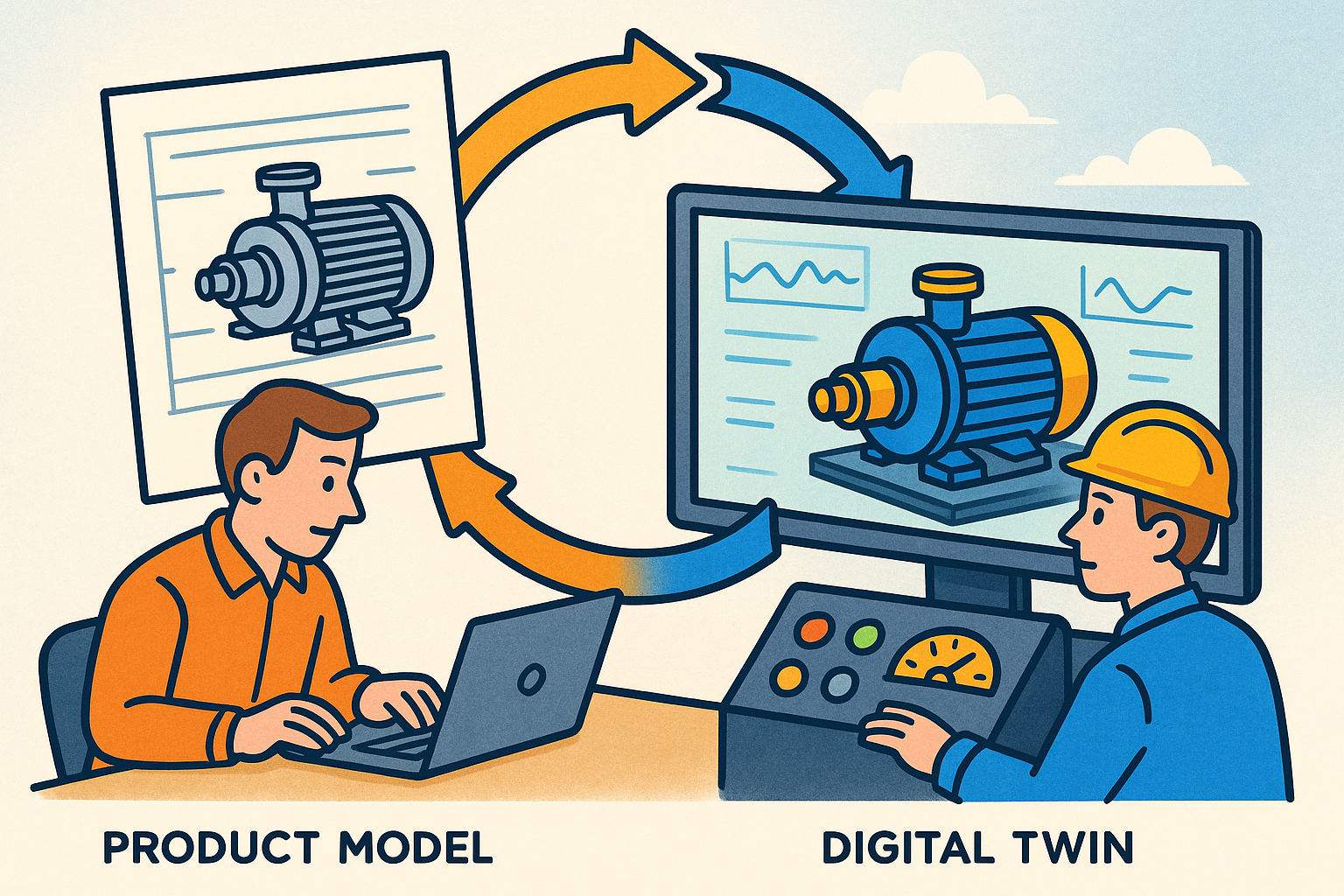


Why synchronizing product models with live systems matters
Close the design–operate loop
Digital product development only reaches its full potential when the models used to design, simulate, and verify a product stay aligned with the product as it is manufactured and used. A concise way to think about this alignment is as a closed feedback loop from operations into design. When **real usage, loads, and environments** flow continuously into CAD/CAE, designers stop guessing at margins and start optimizing with evidence. Rather than treating field data as postmortem reports, the development organization treats it as a living specification that tightens requirements, narrows tolerances, suggests material substitutions, and even updates control strategies to match what customers truly do. The effect is a shift away from punctuated redesigns toward **continuous improvement informed by telemetry**, where every design review leverages fresh distributions of duty cycles and loads instead of worst-case archetypes. This loop does not erase engineering judgment; it focuses it. Engineers choose where fidelity matters, decide when to refit parameters, and codify guardrails that separate safe runtime adaptations from changes that demand formal ECOs. And because the same loop fuels service and quality, product decisions are reinforced by fewer field failures, faster root cause analysis, and better first-pass yield, creating a compelling business case to sustain the investment in a living twin-design stack.
- Feedforward: Convert aggregated duty cycles into design loads and test matrices.
- Feedback: Compare predicted vs observed behavior to refine models and margins.
- Governance: Escalate from calibration tweaks to ECOs based on risk policies.
What “synchronization” really means
Synchronization is more than copying data. It is the deliberate alignment of three linked layers. First, geometry and configuration: a twin should capture options, tolerances, and **wear states** that shape performance, and distinguish **as-designed vs as-built vs as-maintained** structures. That includes serial-number-specific deviations from nominal, captured via metrology and process data tied back to CAD features. Second, parameters and behavior: real machines depart from ideal models through controller gain drift, thermal capacity variation, friction changes, stiffness reductions, and **degradation models** that evolve through life. Synchronization means selectively pushing these measured or inferred parameters into the authoritative models used by design, simulation, and service. Third, state and time context: a model’s accuracy depends on knowing where in the **lifecycle stage** the product sits (commissioning, steady service, end-of-life), and the current **mission profile, environment, and duty cycle**. This context ensures simulators start from an appropriate state and analytics interpret residuals correctly. Together, these layers provide an actionable definition: synchronization is the maintained equivalence class between a physical instance and its model across geometry, behavior, and state, quoted at a declared time and accuracy, and governed by policies that ensure safety, traceability, and intellectual property protection.
- Geometry/config: options, tolerances, nonconformances, repairs, and retrofits.
- Parameters: controller gains, friction coefficients, stiffness matrices, and thermal terms.
- State/time: loads, environments, and usage histories coupled to lifecycle stages.
Lifecycle use cases and practical constraints
Once synchronization is defined, the applications span the lifecycle. In early design, approximate twins let you size components using representative duty cycles, not worst-case folklore. By sampling realistic load spectra, you can reduce overdesign and shift weight or cost into the subsystems that matter. In V&V, co-simulation between lab tests and a digital twin can expose model–hardware divergence long before production, and drive targeted test iterations. In production and quality, mapping metrology and process drift back to CAD features supports **adaptive GD&T**, enabling datum strategies and tolerance bands to reflect empirical capability. In operations, **condition-based maintenance** becomes practical when analytics link sensor paths to features and requirements, and OTA controller updates are first validated against a synchronized twin. Delivering these benefits requires attention to latency tiers—from hard real-time (milliseconds) for control augmentations, through soft real-time (seconds) for monitoring, nearline (minutes–hours) for estimators and planners, and batch (daily) for fleet analytics. It also demands thinking across granularities: component, assembly, product, fleet, and system-of-systems. The payoff is measurable: fewer field failures, material and energy savings, faster ECO cycles, and better first-pass yield, all cross-checked by **model–plant residuals** that trend down over time.
- Latency tiers: hard RT (ms), soft RT (s), nearline (min–hrs), batch (daily).
- Granularity: component → assembly → product → fleet → system-of-systems.
- Outcomes: reduced failures, improved yield, shorter iteration and ECO cycles.
Reference architecture and standards for a robust twin-design stack
Identity, traceability, and the digital thread
A resilient twin-design stack starts with identity. Every artifact—requirement, CAD feature, simulation result, test specimen, serial number, telemetry stream, and service record—needs a persistent identifier and a **traceable lineage** that binds them into a **digital thread**. This thread preserves configuration context across **as-designed, as-built, and as-maintained** structures, capturing variant logic and options that impact physics and service. The thread should resolve both forwards (e.g., “Which serial numbers implement requirement R and how did they perform?”) and backwards (e.g., “Which requirements and tests support the tolerance on this fillet radius?”). Practically, that means adopting an ID scheme consistent across PLM, MES, SCADA, and analytics platforms and exposing it via APIs so tools can anchor events to authoritative structures. It also means modeling the product structure at multiple resolutions, with references from assemblies to features, and from features to constraints and simulation entities. When this identity spine is established, synchronization has somewhere to land: parameters can be written to the right model element; telemetry can be overlaid on the right faces; and service actions can close the loop to update the baseline with controlled, auditable changes.
- Persistent IDs across lifecycle artifacts and instances.
- Bidirectional traceability from requirement to field performance.
- Variant-aware structures linking options to physics and service implications.
Data and integration patterns
The data plane requires fit-for-purpose patterns from edge to cloud. In plants and on assets, OPC UA’s rich information modeling captures typed hierarchies, while lightweight pub/sub like MQTT or DDS moves telemetry efficiently. Time synchronization (PTP/NTP) is critical; without it, co-simulation and residual analysis deteriorate. Ingestion should embrace event sourcing (e.g., Kafka with a schema registry) to ensure that late-arriving or reinterpreted events can be reconstructed. Time-series databases store high-rate signals, while feature stores capture curated variables for ML estimators. The twin service itself maintains a graph: instance topology, states, and links to authoritative models in PLM, CAD, and CAE. On the design side, **tool bridges** expose plugins, REST, or GraphQL endpoints to push/pull parameters, overlay telemetry on geometry, and trigger re-simulations. This approach avoids brittle file-based workflows and makes synchronization programmable. Finally, the integration should honor **latency tiers** and **SLOs** with clear contracts: what is hard real-time, what is nearline; what is sampled, what is event-driven; and how tools degrade gracefully during data gaps or schema evolution.
- Edge: OPC UA for structure, MQTT/DDS for pub/sub, PTP/NTP for time sync.
- Core: event sourcing, time-series DBs, and ML feature stores.
- Twin: graph of instances with links to CAD/PLM/CAE models and APIs for tools.
Model exchange and semantics
Interoperability rises or falls on shared semantics. For geometry and product structure, STEP AP242, JT, and glTF cover neutral exchange and visualization; QIF binds metrology to features; LOTAR strategies ensure long-term readability. For systems and behavior, SysML v2 provides a modern language for requirements, structure, and interfaces, while FMI/FMU packages support **co-simulation across tools**. On the twin side, ISO 23247 and **Asset Administration Shell (AAS)** standardize how industrial assets expose digital submodels, and formats like DTDL can serve instance schemas in IoT stacks. The goal is to express not just shapes, but meaning: which face is a datum; which parameter is a controller gain; which signal corresponds to that arm’s torsional mode. When semantics are clear, you can automate more: constraints convert directly into test vectors; telemetry lands on the right object; and rule engines can reason about the consequences of change. Without them, teams revert to brittle glue code and recoding metadata by hand, yielding schema drift and “unknown unknowns.” Standards let you decouple suppliers and internal tools, reduce integration cost, and keep the door open for future analytics and visualization advances.
- Geometry/structure: STEP AP242, JT, glTF; QIF for metrology; LOTAR for longevity.
- System/behavior: SysML v2 for structure/requirements; FMI/FMU for co-sim.
- Twin semantics: ISO 23247, AAS, and DTDL for instance schemas and submodels.
Security and governance
Keeping models live should never weaken security. Adopt **zero-trust** access with device and user attestation, signed telemetry, and signed model packages. Encrypt at rest and in transit, and rotate keys. Manage SBOMs and model provenance so every model element carries lineage to data and code versions, and apply watermarking to shared geometry or material libraries to deter leakage. Governance needs **policy-as-code** for retention, export control, and IP boundaries, especially in supplier ecosystems where only specific submodels can cross organizational lines. Equally, set approval workflows for parameter and geometry changes: small calibration updates might be auto-approved within risk bands, while material or geometry changes must trigger ECOs with multiparty signoff. Finally, instrument the stack with audit logs that are tamper-evident. When trust is engineered in from the start, synchronization accelerates instead of stalls in security reviews, and stakeholders confidently consume shared twins knowing compliance is preserved even as the models evolve.
- Zero-trust: attestation, signed payloads, and encryption everywhere.
- Provenance: SBOMs, training data lineage, and watermarking of shared assets.
- Policy-as-code: retention, export control, and supplier IP boundaries enforced.
Methods to keep models “live”: calibration, estimation, and controlled updates
State estimation and hybrid modeling
Most states that matter to physics are not directly measured. Observers, Kalman filters, and particle filters estimate them, fusing sensors with dynamic models. In many products, this is a hybrid exercise: a physics-based core provides structure, while data-driven terms absorb unmodeled dynamics. Constrained optimization ensures estimates respect kinematics and bounds, while **drift detection** monitors residuals between predicted and measured signals to trigger re-identification when thresholds are exceeded. For speed, reduced-order representations and **gray-box ROMs** replace full CFD/FEA, while physics-informed neural networks embed conservation laws in trainable surrogates. In practice, you design estimators for tiers: hard real-time observers for control loops; soft real-time filters for health; nearline batch smoothers to reset initial conditions for simulators. These estimators become the heartbeat that keeps the twin aligned, pushing state snapshots and confidence intervals into the twin graph and back into CAE initial conditions. The result is a coherent picture of the product’s internal conditions, even when sensors are sparse, that enables predictive maintenance, performance tuning, and meaningful comparisons between model and plant across operating regimes.
- Observers/filters infer unmeasured states while honoring physics constraints.
- Residuals drive drift detection and automatic re-identification triggers.
- Tiered estimators align with latency requirements from control to planning.
Parameter identification and uncertainty
Keeping behavior honest means fitting parameters to real data and quantifying what you don’t know. Batch methods (least squares, adjoint/gradient-based) refine parameters with high-quality experiments, while online variants (e.g., recursive least squares) adapt gains and coefficients as conditions change. Bayesian inference captures uncertainty explicitly, producing posterior distributions for parameters that flow into performance margins and tolerances. Those uncertainties should not stay buried in analytics notebooks: surface **confidence bounds** in CAD/CAE overlays, so designers see error bars on temperatures, stresses, or deflections. This prevents false precision and prompts decisions about where to invest in better sensing or modeling. Lean into **active learning**: schedule safe experiments or A/B controller tweaks to shrink uncertain parameter spaces, especially where uncertainty most affects risk. Integrate identification into reproducible pipelines with versioned data and code, so re-runs generate consistent results and models are comparable over time. Ultimately, the twin is not a single set of numbers; it is a distribution-aware model whose decisions—whether maintenance or redesign—explicitly weigh uncertainty against cost and safety.
- Batch and online identification to keep parameters tied to reality.
- Bayesian approaches propagate uncertainty into margins and dashboards.
- Active learning plans safe maneuvers to reduce high-impact unknowns.
Geometry/configuration synchronization and simulation-in-the-loop
Geometry changes across life, and synchronization must reflect it. Build parameter maps linking sensors and process data to CAD features: wear patterns mapped to fillet radii, backlash to gear tooth profiles, creep to bolt preload loss. Use QIF to connect metrology to features and generate automated deviation reports that suggest tolerance schema updates in PLM. Guard all updates with rules that distinguish field-calibratable constants from changes that require ECOs: a control offset might auto-apply; a material substitution must not. With behavior and geometry aligned, wire **simulation-in-the-loop**. Orchestrate FMI co-simulations that step when telemetry arrives, respecting real-time budgets. Use **reduced-order models**—modal truncation, POD, or neural surrogates distilled from high-fidelity CAE—to answer “what-if” questions at interactive speeds. For fleets, aggregate many-unit data into representative duty cycles and load spectra for next-generation design inputs, ensuring weighting reflects environment and usage diversity. The net effect is a design stack where simulators and field instances share a heartbeat, geometry deviations are not anecdotes but structured data, and engineering changes are provably beneficial before they land on a line or in the wild.
- Metrology-to-CAD via QIF, with rules for safe vs ECO-bound updates.
- Event-driven FMI co-sim orchestrated to real-time constraints.
- Fleet aggregation converts raw data into design-ready load spectra.
Operations, UX patterns, and CI/CD for twins
A living twin earns trust through experience and user interfaces. In the CAD or PLM context pane, show telemetry heatmaps and **anomaly overlays** directly on 3D assemblies, with clickable paths from sensor to feature to requirement. Embed health scores and **remaining useful life** estimates beside BOM entries, giving design and service a shared picture. Define SLOs for latency, data completeness, and model accuracy; when they are violated, alert and fall back to simpler models or conservative policies. On the delivery side, treat twin updates as a product. Maintain **model registries** with semantic versioning, document input/output schemas, and track provenance. Build reproducible training and calibration pipelines; run OTA pre-checks in sandbox twins; deploy canaries with rollback. Cover rare events with synthetic data to validate estimator robustness. For users, design workflows that make it one click to push a parameter into CAE, or one query to list all requirements linked to a drifting residual. In short, the twin is not just a data store—it is a **CI/CD-enabled system** with clear ownership, release notes, and SLAs, delivered through UX patterns that make synchronized models the default way engineering decisions get made.
- 3D overlays connect signals, features, and requirements for explainability.
- Defined SLOs and fallbacks sustain reliability under imperfect data.
- CI/CD: registries, sandboxes, canaries, and synthetic data increase confidence.
Conclusion: building living models, not static files
Start small, iterate fast
The path to synchronized models is incremental. Pick a high-impact subsystem—thermal loops, vibration paths, drivetrain controls—and map a tight loop from sensors to model parameters to decisions. Keep the scope simple: one set of signals, one estimator, one CAE callback, one dashboard. Show that feeding **real duty cycles** into design reduces cost or mass without sacrificing reliability. At the same time, establish identity and traceability early, because it is the backbone of every later integration; without it, you cannot anchor telemetry to features, or parameters to requirements. Run weekly iterations: add a parameter, refine an observer, test a co-simulation, and capture before/after residuals. Instrument the process with clear metrics—iteration time, ECO cycle time, data latency—and publish them to stakeholders. Early wins build trust that synchronization improves outcomes; early instrumentation keeps the effort honest and focused. As capability grows, expand the loop sideways to adjacent subsystems and upward to fleet-level aggregation. The critical mindset is to treat the twin-design connection as an engineered product, not a project, with a backlog, owners, and roadmaps that commit to reliability as well as features.
- Choose one subsystem; wire one closed loop end-to-end to prove value.
- Stand up identity and traceability; retrofit later is costly and brittle.
- Iterate weekly with visible metrics and tight feedback to stakeholders.
Standardize to scale
Scaling synchronization hinges on open schemas and disciplined boundaries. Adopt AP242 for geometry/product, SysML v2 for structure and requirements, FMI/FMU for model interchange, QIF for metrology, and **AAS/DTDL** for twin semantics. These choices prevent bespoke glue and **vendor lock-in**, and make it feasible to onboard suppliers who can participate at the submodel level without gaining access to your entire design vault. Treat the twin graph as a first-class system: assign ownership, publish APIs, define SLAs, and budget for reliability engineering. Segment the stack into modular services—ingestion, twin service, analytics, visualization—with documented contracts so teams can evolve independently. Finally, plan for long-term archiving (LOTAR) and schema evolution, including migration tools and deprecation policies. Standardization is not bureaucracy; it is an accelerator that lets you integrate a new sensor, model, or supplier in days rather than months, confident that semantics will line up and security will hold. When standards underpin the stack, synchronization stops being a heroic integration exercise and becomes a repeatable, scalable capability.
- Open standards reduce integration friction and future-proof the stack.
- First-class twin graph with APIs and SLAs clarifies responsibility.
- Modular services and versioned schemas enable parallel evolution.
Engineer for reliability and trust
Trust is earned by systems that behave predictably. Bake in security with zero-trust principles and cryptographically verifiable provenance. Make every model change traceable to data and decisions, including who approved it and why. Elevate uncertainty as a first-class concept: show confidence bounds, not just means; integrate risk models into maintenance and design decisions. Enforce clear guardrails about what the field may change (calibration constants with bounded ranges) vs what requires ECO (geometry, materials, safety-critical logic). Simulate suspected changes in **sandbox twins** before touching production assets, and confirm on canary units with rollback paths. Instrument SLOs for latency, completeness, and accuracy, and define graceful degradation: when data drops, models should not silently extrapolate beyond validated regimes. Communicate through transparent release notes and dashboards, so design, production, and service share the same picture of model health. Reliability is not a phase; it is a discipline that turns synchronization into a durable capability, where stakeholders can count on the twin to be accurate enough, timely enough, and safe enough to drive real decisions.
- Security and provenance by default; approvals tied to risk tiers.
- Uncertainty visible in CAD/PLM contexts to counter false confidence.
- Sandboxes, canaries, and SLOs keep changes safe and predictable.
Measure what matters and avoid common pitfalls
Teams sustain investment in synchronization by tying it to outcomes. Track design iteration time and ECO cycle time to show how a live twin reduces delays. Monitor **model–plant residuals** as an objective measure of model fitness; steadily falling residuals signal learning. Quantify maintenance savings and energy or performance gains attributable to better parameter fits or control updates. Publish these metrics to guide prioritization: invest next in the subsystems where delta-to-value is largest. At the same time, dodge common traps. Do not chase **full fidelity everywhere**; use layered models and **reduced-order surrogates** where latency matters. Avoid the “monolithic twin” syndrome by composing twins from modular, testable components with clear contracts; a single giant model is fragile and opaque. Plan change management so field-learned updates enter baselines safely, with clear ECO triggers and signoffs. And be mindful of data drift and schema creep; treat schemas as versioned assets with automated tests. By measuring what matters and steering clear of these pitfalls, you build a practice that delivers cumulative advantage: each iteration compounds into more accurate models, faster decisions, and demonstrable business value.
- Outcome metrics: iteration speed, ECO latency, residuals, maintenance, and energy.
- Layered fidelity and ROMs where real-time constraints dominate.
- Modular twins and disciplined change management keep complexity in check.
Also in Design News