
Your Cart is Empty


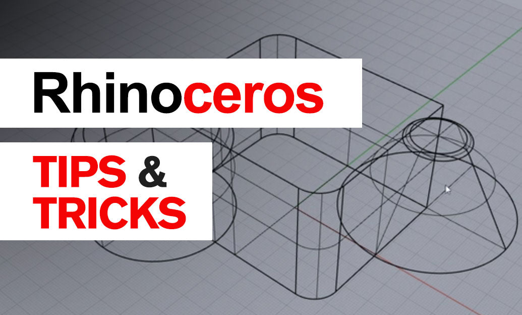

Choose the scaling method that matches your design intent: preserve proportions with Scale, adjust a planar footprint with Scale2D, or change one directional dimension with Scale1D. The key is controlling both the scale factor and the point that stays fixed.
Start with a reliable reference. Before scaling, measure the relevant geometry with Distance. Confirm your document units, then enable appropriate object snaps, such as End, Mid, or Cen. Choose a base point deliberately: a mounting corner, center, or connection point usually makes more sense than an arbitrary location.
-
Use
Scalefor proportional changes. Select the objects, run the command, specify the base point, and enter a factor. A factor of1.25enlarges every linear dimension by 25%;0.8reduces every linear dimension by 20%. Angles and overall proportions remain unchanged. -
Use
Scale2Dfor footprint adjustments. This scales in the active construction plane’s X and Y directions while leaving the perpendicular dimension unchanged. With the World Top construction plane active, you can enlarge a product’s footprint without changing its height. Confirm the construction plane before proceeding. -
Use
Scale1Dfor directional changes. Specify a base point and define the scaling direction through the reference-point workflow. Geometry changes along that direction while perpendicular dimensions remain unchanged. This is useful when adjusting an enclosure’s length without changing its width or height. -
Use
ScaleNUfor independent axis factors. When all three dimensions need different adjustments, this command provides separate scaling factors along the construction-plane axes. Establish the correct construction plane first, especially for rotated components.
Calculate exact factors instead of estimating. Divide the desired dimension by the current dimension. For example, changing a 240 mm housing to 300 mm requires 300 / 240 = 1.25. Apply that factor with Scale1D if only its length should change, or with Scale if the entire object should grow proportionally.
For point-based accuracy, use the commands’ reference-point workflow: establish the original extent with snapped points, then specify the target extent. This avoids rounding a calculated factor and is particularly helpful when matching existing geometry. Watch the command-line prompts rather than placing reference points by eye.
Check what nonuniform scaling changes. Stretching a finished part also stretches its details:
- Circles can become ellipses, affecting holes and cylindrical features.
- Wall thicknesses, fillets, and clearances may change unevenly.
- Assembly interfaces may no longer match neighboring components.
If critical features must retain their dimensions, consider scaling the underlying form before creating holes, fillets, and other manufacturing details. Keep an unchanged copy on a separate layer so you can compare the result and recover the original design quickly.
Finish by measuring the revised dimensions and inspecting important interfaces. Remember that scaling geometry is not the same as correcting document units or changing a layout’s print scale.
For more Rhino workflow resources, explore NOVEDGE. Browse Rhino at NOVEDGE when evaluating software options for your modeling workflow.