Your Cart is Empty
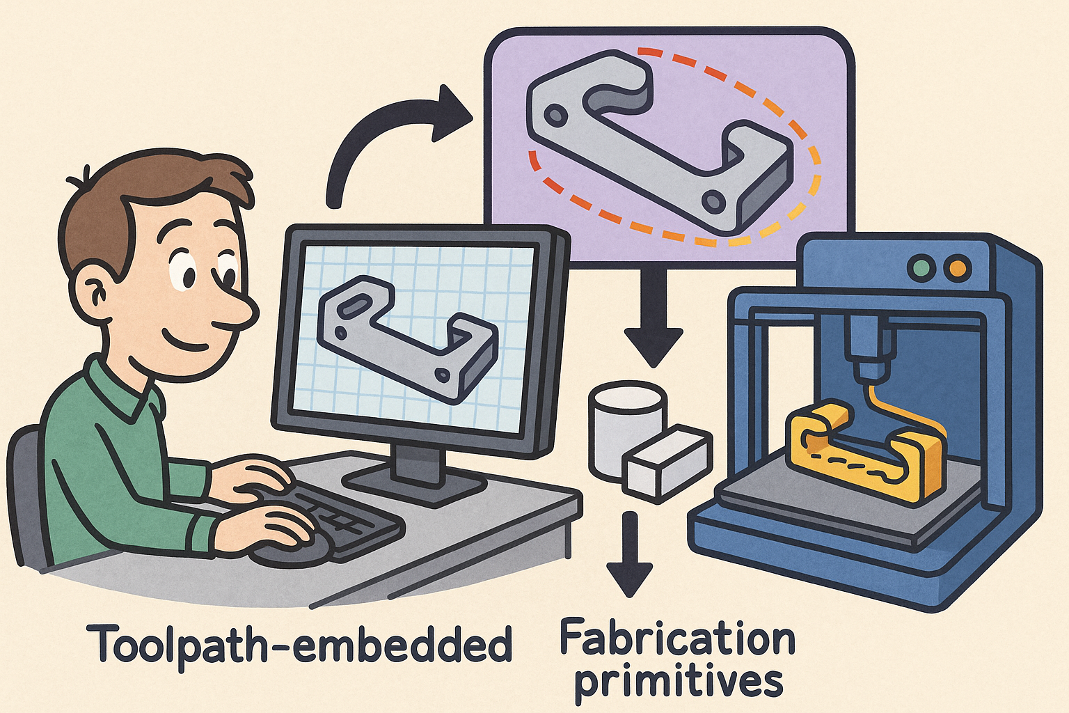
Path-First Modeling: Embedding Toolpath-Aware Constraints and Fabrication Primitives into CAD Kernels


Why Toolpath-Aware Constraints Belong in the Modeler
The gap today
Modern design teams still rely on a split-brain workflow: geometry is authored in an idealized CAD kernel and later “made real” by CAM, often after major decisions are locked. This separation forces manufacturability to become an audit instead of an influence. In subtractive contexts, the model’s sharp internal corners, deep pockets, or skinny ribs look innocent inside the kernel’s exact arithmetic, yet they turn into uncuttable crescents, unreachable zones, and chatter-prone features the moment a tool radius and fixture must be respected. In additive contexts, the same disconnect manifests as walls that cannot be quantized to bead multiples, overhangs that require elaborate supports, or enclosed cavities that violate powder evacuation or resin drainage. The consequence is a costly loop: adjustments are discovered too late, and fixes in CAM are non-local—one local fillet forces a different cutter, which changes strategy, which alters surface finish and thermal profile, which feeds back into tolerance or warpage.
When manufacturability checks are performed post hoc, the geometry’s distance to feasibility is opaque. Designers operate with implicit, incomplete heuristics, while CAM programmers compensate with tool-specific patchwork. Time-to-first-part stretches, variation increases, and process predictability suffers, especially when designs jump between shops or machines with different kinematics. The root problem is epistemic: the model has no representation of the machine’s motion limits, deposition physics, or cutting accessibility. The kernel knows about edges and faces, not about reach cones, scallop height, or bead stacking. By the time violations are detected, the geometry’s topology has already excluded simpler toolpath strategies. A better path is to encode the machine’s worldview directly into the model so that geometry is born consistent with a feasible path.
Toolpath-aware constraints defined
Toolpath-aware constraints are geometric limits and preferences directly derived from tool motion, deposition physics, and machine kinematics, baked into modeling operations rather than bolted on afterward. Instead of generic “minimum radius” rules, the constraint explicitly states that the minimum internal radius is the end mill’s cutter radius (or the nozzle’s turning envelope)—a bound that emerges from a Minkowski dilation of the tool. Instead of abstract “thin wall” warnings, the constraint says walls must be integral multiples of bead width w, with corner curvature respecting a maximum allowable κ that avoids under-extrusion or speed stalls. For laser powder bed, resin vats, and wire arc, constraints tie orientation to peel, recoater, or gravity; for 3-axis and 5-axis milling, constraints bind feature accessibility to reachability cones and fixture contact manifolds.
Such constraints are not rules of thumb but first-class mathematical objects linked to a specific process descriptor and toolpath policy. They are evaluable locally on faces/edges and globally through fields that live in the model. They can be satisfied analytically by design operators while you sketch, swept, or offset. For example, as a designer attempts to create a pocket, the modeler enforces that the pocket’s fillets are no smaller than R of the intended cutter, step-over s implies an iso-scallop bound ε on finishing, and the pocket is trimmed to the reach set of the selected machine orientation. In additive, the operator that forms a vertical wall will snap thickness to n×w, apply curvature filtering to respect κmax, and enforce venting connectivity when cavities are detected. The result is geometry that declares its reliance on the machine’s feasible path rather than geometry that assumes a path will be found later.
Failure modes this prevents
Embedding constraints at modeling time neutralizes common, expensive failure modes by eliminating them before they can arise. In additive, the modeler can refuse or restructure features that would otherwise provoke support proliferation, unquantized walls, or thermal spikes, while in subtractive, it can prevent inaccessible corners, fixturing deadlocks, or surface quality regressions due to excessive scallop. The effect is fewer cycles between design and CAM, more predictable roughing/finishing behavior, and shorter time-to-first-good-part. Consider the following categories of avoidance:
-
Additive-specific avoidance:
- Unsupported overhangs beyond θmax are flagged and either oriented, bridged within Lmax, or reparameterized to self-supporting angles.
- Non-quantized wall thickness is snapped to n×w, and corners exceeding κmax are gently smoothed to maintain constant deposition speed and avoid under-extrusion.
- Thermal hotspots are surfaced by path density and pause-time heuristics, prompting fillet expansion, ribbing, or path redistribution.
- Unventable powder or resin cavities are automatically pierced by vent lattices that meet minimum diameter and connectivity rules.
-
Subtractive-specific avoidance:
- Impossible internal corners are blocked unless filleted to ≥ Rmin(tool) derived via Minkowski sums.
- Unreachable pockets on 3-axis are diagnosed by line-of-sight fields, suggesting 5-axis reorientation or relief channels.
- Excessive scallop height from step-over s is bounded, guiding tool diameter or surface finish expectations.
- Collisions and fixturing conflicts are avoided by checking against a contact manifold and virtual fixtures during feature creation.
By preventing these issues at the moment of geometry authoring, we compress downstream iteration and rework. The model ceases to be a wish list and becomes a machine-credible object. In practical terms, a designer can ask for a small chamfer and immediately see whether the selected tool and setup can honor it, or whether a different tool or sequence is implied. This proactive discipline keeps costs, surface quality, and lead time inside predictable envelopes.
Design objective shift: path-first modeling
The most profound change is philosophical: the design objective moves from “a shape that will be toolpathed later” to “a shape that exists because a feasible toolpath exists.” This is path-first modeling. Instead of emulating sculpture and expecting CAM to rationalize it, the modeler composes features by instantiating toolpath policies that guarantee realizability on a particular process. In additive, you declare “add N perimeters and a raster infill at 45° with variable layer height tied to curvature,” and the solid arises from that intent with bead quantization maintained. In machining, you start from a reachability cone and cutter radius, apply iso-scallop bounds, and let the pocket geometry adapt to ensure finish consistency and tool clearance.
Path-first modeling rewards designers with faster iteration loops and fewer surprises on the shop floor. Optimizations become meaningful: when a fillet is increased, the modeler can immediately show the ripple effects on cutter choice, path length, and finish time. When an orientation changes, collision scores and supportability update in real time. The trade space becomes a multidimensional dashboard rather than a series of disconnected checks. This shift also changes collaboration: CAM experts become co-authors of geometry by encoding their strategies as reusable constraints and primitives, making the team’s production knowledge portable and consistent across projects. Ultimately, geometry becomes the certificate of an already-existing plan of motion, instead of an aspiration to be negotiated downstream.
The Fabrication Primitive Set — Formalizing Toolpath-Aware Geometry
Core concept: a fabrication primitive
A fabrication primitive is the atomic unit that fuses form and making: (geometry operator) × (process descriptor) × (toolpath policy). The geometry operator can be a sweep, offset, pocket, shell, or lattice. The process descriptor encodes machine class, tool types, material, and key physics (peel, heat, flow, stiffness). The toolpath policy defines motion style and constraints—contour-first then raster, climb vs. conventional, spiral vs. zig-zag, bead count, variable layer height, orientation locking. With this triple, the same “pocket” operator becomes different objects for CNC, SLA, or SLS because it carries process causality, not just shape.
Examples make the idea concrete:
- Bead-sweep (FDM/DED): Sweep a centerline with bead width w, layer height h, and curvature κmax. Walls are quantized to n×w, and corners are smoothed to respect maximum turning without starving the bead. The result is a solid that knows its perimeter count and allowable speed profile.
- Contour + raster pocket (CNC): Realizable by tool radius R, step-over s, scallop limit ε, and a reachability cone Ω. Fillets are clamped to ≥ R, and the final surface error is guaranteed by ε with automatic rest machining selection for corners.
- Peel-limited shell (SLA/DLP): Faces are oriented so that peel force stays below Fmax, and holes/vents are inserted to ensure drainage. The shell thickness respects minimum cure depth and anisotropy in exposure.
- Powder-clearable cavity (SLS/MJF): Internal channels meet minimum diameter, curvature, and connectivity, with automatic escape paths traced to the outside world, preventing trapped powder.
Mathematical lenses for constraints
Toolpath-aware constraints can be expressed with rigorous mathematical operators that map cleanly onto kernel operations. Minkowski sums (and their dual, erosions) with the tool as a structuring element encode the fundamental “no internal corner sharper than tool radius” rule, and similarly define offset-able regions for abrasion, laser spot size, or bead envelope. This morphology makes fillet sizing and minimum gap enforcement algebraic instead of ad hoc. For access, reachability fields parameterize feasibility as cones or volumes: 5-axis cones define allowable approach directions; 3-axis line-of-sight maps encode the shadow of the tool and holder across the stock. Surfaces carry iso-scallop bounds linking step-over s to cusp height ε via curvature, giving a direct surface error constraint that the kernel can uphold while offsetting and projecting paths.
Quantization constraints snap thickness and gaps to multiples of tool, bead, or spot size. This is crucial for additive where bead stacking creates discrete thickness levels, but also for subtractive where minimum slot widths or rest machining thresholds must be honored. Additional lenses include thermal accumulation proxies derived from path density and dwell time, and kinematic feasibility captured as maximum curvature of motion or acceleration limits in joint space. By turning each lens into an evaluable constraint, the modeler can apply them during sketch inference, feature edits, and Boolean operations, preventing topology that would be impossible to offset, unreachable to cut, or unstable to print. The same math drives visualization: dilations show “keep-out” halos around tools; iso-scallop maps paint finish gradients directly onto surfaces; and reach cones become live indicators of access risk.
Data structures embedded in the model
To keep constraints alive, the model must carry process-aware fields and annotations alongside its B-Rep or volumetric representation. An orientation field φ(x) associates each point or face with preferred approach directions and allowable tilt, enabling immediate checks against machine axes. A path field p(x) expresses local toolpath intent—contour, raster, spiral—while a step-over field σ(x) ties local curvature to finishing error. Supportability S(x) tracks self-supporting angles, bridging limits, and projected support mass. A fixturing/contact manifold F records viable grips, datums, and clamping surfaces, so that accessibility and collision checks are performed with realistic boundary conditions, not in a vacuum.
Faces and edges carry constraint annotations: R ≥ Rmin(tool) for fillets; θoverhang ≤ θmax for printable faces; Lbridge ≤ Lmax for bridges; w|h quantization for walls; Ω for approach cones; and ε for surface finish targets. These annotations remain live as edits propagate, allowing the kernel to enforce them through parametric solves and Boolean operations. Where meshes are necessary (e.g., for GPU visualization), the volumetric/B-Rep hybrid retains exact constraint definitions so that checks and offsets are done analytically, not merely sampled. The result is a model that is not just geometry, but a compact, queryable database of manufacturing intent. Teams can inspect φ, p, σ, S, and F to understand why a face exists, how it will be made, and what alternatives the constraints still permit.
Manufacturability metrics exposed early
Early exposure to manufacturability metrics turns DFM from a gate into a guide. The modeler can visualize feasible and infeasible regions in real time: as you drag a fillet, faces turn green when R ≥ Rmin(tool) and red when they fall short. Additive surfaces display overhang heatmaps against θmax, while cavities illuminate if vent connectivity is lost. Time and quality proxies appear as you adjust dimensions: path length is estimated from p(x) and σ(x), scallop maps show ε across the surface, and thermal risk is aggregated from local dwell and path stacking density. Collision risk scores update with fixture selection, using F to test wrench stability and clamp clearances across orientations.
Practical feedback becomes actionable suggestions. Instead of a generic error banner, the system proposes: “increase fillet to 3.2 mm for a 6 mm end mill,” “rotate orientation by 15° to keep overhang within 45°,” or “add a 2×w vent lattice to evacuate powder.” These suggestions originate from constraints and fields, not from opaque rules. Moreover, metrics update continuously as parameters change, enabling multi-objective trade-offs: increase thickness to meet stiffness, watch bead count snap to n×w, see time increase by Δt, and learn whether scallop bounds still meet ε in finishing. Because the data structures are embedded, these metrics persist into assemblies and across revisions, allowing automated checks in CI pipelines and richer collaboration with CAM and manufacturing teams.
Embedding Primitives into Design Software Workflows
Kernel-level integration
Bringing toolpath-aware constraints into the kernel demands tight coupling between geometric solvers and manufacturing clauses. Dimensional and assembly constraints must share a solver fabric with manufacturing constraints so that, for instance, a tangent condition and a minimum fillet derived from tool radius R resolve simultaneously. Robust offsetting and Booleans must be aware of erosion/dilation limits to avoid skinny slivers or non-manifold artifacts that violate cutter or bead envelopes. Rather than compute generic offsets and prune failures afterward, the kernel should offset within the morphology induced by the tool—effectively offsetting with a structuring element—so that the result is realizable by construction.
Volumetric/B-Rep hybrids are crucial because process fields (φ, p, σ, S, F) are volumetric in nature even when the boundary remains exact. A hybrid kernel can store smooth fields over a signed distance function while keeping parametric faces intact, enabling analytical evaluation of scallop errors, reach cones, and quantization during feature operations. This also opens the door to differentiable evaluations: gradients of path length or scallop error with respect to feature parameters can be computed inside the solver, exposing real-time sensitivity. The payoff is reliability and speed: constraints are enforced at the same locus where dimensions are solved, Booleans are executed in a realizability-aware manner, and the model always stays inside the feasible set defined by the selected machine and process. That stability is the foundation for path-first operators and live toolpath previews that don’t flicker or collapse under small edits.
Real-time guidance and inverse design
Once the kernel is constraint-aware, the user interface can elevate guidance from warnings to co-design. Live toolpath preview becomes the default visualization, updating with each sketch stroke or feature drag. Violations are flagged in-line with specific fixes tied to machine context: “Switch to a 3 mm corner radius or choose a 4 mm cutter,” “Lock nozzle orientation for this overhang,” or “Reduce step-over to meet ε ≤ 8 μm.” Beyond guidance, inverse design becomes possible: differentiable or surrogate toolpath estimators provide gradients of time, roughness, or risk with respect to dimensions and process parameters, enabling local optimization and even global searches under constraints.
Path-first operators simplify intent expression. You can say, “Add N perimeters here” and the system thickens the wall by exact multiples of w, preserving bead count through downstream edits. “Lock nozzle orientation” freezes φ locally, forcing self-supporting angles while rerouting infill direction fields to minimize jerk. “Guarantee powder venting topology” inserts a minimum-diameter connectivity graph that never disappears under future Booleans. For machining, “Ensure cutter access” inserts automatic fillets or relief pockets wherever reachability cones would otherwise fail, while “Bound scallop height” keeps finishing within ε by modulating step-over per curvature. These operators aren’t macros—they are intentful primitives that drive both shape and motion, shrinking the semantic distance between what a designer asks for and what a machine will do.
Cross-process and multi-axis considerations
Real parts rarely live in a single process lane, and even within a lane, axis count and setup strategy matter. Orientation planning should be embedded in features as reachability cones for 5-axis, with automatic search over tilt/rotation that trades off collision risk, tool length, and stiffness. For 3-axis, line-of-sight volumes identify shadows early; the modeler can autogenerate relief features or suggest setup re-sequencing to restore access. Additive benefits immensely from process-specific tuning: variable layer height tied to curvature smooths domes without exploding build time; corner rounding maintains constant deposition speed and jerk; and anisotropy-aware infill direction fields align filament or scan vectors with load paths to maximize stiffness or fatigue life without thickening.
Hybrid workflows become first-class citizens with sequencing of primitives. A design might instantiate an AM preform with bead quantization and supportability constraints, followed by a CNC finishing pass that imposes scallop bounds and reachability fields. The constraint graph persists across steps so that stock allowance reflects tool radius needs, and additive fillets are placed to avoid forcing tiny cutters later. The designer sees the entire manufacturing itinerary—additive, stress relief, rough milling, finishing—expressed in constraints that the geometry itself respects. That continuity unlocks aggressive design-to-part cycles: fewer setups, fewer surprises, better surface integrity, and a model that never diverges from the plan of motion.
Governance and interoperability
If toolpath-aware constraints are to reshape workflows at scale, they must survive beyond a single CAD session. Persisting constraints and toolpath policies in model metadata is essential. Extensions to standards like STEP AP242 or STEP-NC can carry process descriptors, reachability cones, scallop targets, bead quantization, and fixture manifolds. With standardized fields, shops can load a model and immediately see the intended policy set, not just neutral geometry. This transparency reduces interpretation risk and aligns programming strategies across machines and vendors.
Governance also means automation. Continuous Integration (CI) for manufacturability runs path-feasibility unit tests on pull requests: R ≥ Rmin(tool) checks, θoverhang ≤ θmax validations, ε maps within tolerance, and fixture solvability on target machines. Failing checks gate merges, pushing problems left. Template libraries of process-validated primitives—per machine, material, and shop capability—accelerate onboarding and drive consistency. Designers pick from a curated set of features guaranteed to be cuttable or printable on specific cells. Audit trails capture which constraints were active at release and which suggestions were accepted or overridden, tightening feedback loops with production. Interoperability plus governance turns path-aware modeling from a niche practice into a repeatable, scalable discipline that interoperates smoothly with CAM, PLM, and MES.
Conclusion
From policing to real-time synthesis
When toolpaths become first-class citizens in modeling, the old design–CAM divide collapses. DFM stops being a late-stage policing function and becomes real-time synthesis—helping you author geometry that already embodies motion, access, and quality. The transformation is pragmatic: constraints like minimum internal radius, iso-scallop bounds, reach cones, bead quantization, and vent connectivity are enforced and visualized at creation time, not merely checked after the fact. The payoff is large yet mundane in the best way: fewer revisions, clearer expectations, more predictable schedules, and parts that land on the floor with surfaces, tolerances, and mechanical properties that match intent. Teams spend less time negotiating feasibility and more time optimizing performance and cost because the model is anchored to what machines can actually do.
By encoding what’s realizable via fabrication primitives, the modeler renders tribal knowledge explicit and portable. Toolpath-aware operators become a shared language between design and manufacturing: “Add N perimeters,” “Limit peel force,” “Bound scallop height,” “Guarantee powder venting topology.” With embedded fields—φ(x), p(x), σ(x), S(x), and F—the model becomes an executable specification of motion and quality. The result is a smoother pipeline, better surface integrity and dimensional stability, and a stronger bridge between simulation, programming, and execution. The culture shifts from fixing violations to exploring trade spaces in which production realities are baked into the creative act.
The path forward
What remains is straightforward engineering and ecosystem work. Kernels must be enriched with morphological and reachability math so that erosions, dilations, and access cones are first-class operations alongside offsets and Booleans. Vendors should ship constraint-aware features that expose scallop, bead, and reachability targets as editable parameters—backed by differentiable or surrogate estimators for time and roughness—so that optimization is not an afterthought. Toolpath policies and constraints need persistent, standardized metadata so intent survives across tools and organizations. Shops and design teams should build libraries of process-validated primitives aligned to their machines and materials, and wire manufacturability CI into their PLM/ALM flows to keep feasibility ahead of release gates.
The net effect is compelling: designers author geometry that is already manufacturable because a feasible, high-quality path already exists in its DNA. This is path-first modeling as a practical discipline, not an ideology. It shrinks iteration cycles, de-risks launch, and raises the floor on quality and repeatability. As constraints become collaborators, design software evolves from a shape sketcher into a fabrication partner—one that respects the realities of tools, motion, and material, and turns them into creative leverage rather than limitations. In that world, the best parts are not those that barely pass a late-stage DFM audit, but those whose very form is the signature of a well-orchestrated, physically grounded plan of motion.
Also in Design News