Your Cart is Empty


Model-Driven Technical Illustration for Automated Exploded Views


From Manual Drafting to Model-Driven Technical Illustration
The historical shift from drawing to product intelligence
Technical illustration has always existed at the boundary between design intent and practical understanding. In the era of manual drafting, an exploded view was created by interpreting engineering drawings, redrawing components, positioning them by hand, and adding annotations that depended heavily on the experience of the illustrator. Even when 2D CAD replaced ink, templates, and drafting boards, the process remained fundamentally manual: the illustrator still had to decide how parts should separate, which components deserved emphasis, where balloons should be placed, and how a service technician would read the sequence. The introduction of 3D CAD changed the source of truth, but for many organizations documentation continued to behave like an external artifact. Models were exported, screenshots were captured, views were traced, and manuals were published as if the underlying product were frozen in time. Today, that separation is collapsing. Technical documentation is increasingly becoming a **live extension of the engineering model**, using assembly hierarchy, metadata, geometry, and product structure to generate visual communication directly from the same data used for design, simulation, manufacturing, procurement, and service planning.
Why traditional documentation remains fragile
Traditional documentation workflows remain slow because they duplicate decisions that have already been made inside the engineering environment. An assembly model already contains spatial relationships, mating conditions, part identities, revision information, and often detailed manufacturing or service metadata, yet conventional illustration processes frequently ignore this intelligence. A technical writer or illustrator may manually create views, manually explode parts, manually enter callout numbers, and manually synchronize the bill of materials with the drawing. Each manual step creates an opportunity for inconsistency. A washer may be hidden behind a bracket in one view, a fastener may be numbered differently between an installation guide and a spare parts catalog, or a late revision may introduce a redesign that never reaches the maintenance manual. This is especially problematic in products with hundreds or thousands of components, where small visual discrepancies can lead to incorrect assembly, wasted technician time, or safety-relevant misunderstandings. The core weakness is not the skill of the documentation team; it is the fact that the workflow treats documentation as a disconnected downstream deliverable rather than as a structured, data-driven representation of the product.
- Manual view creation often requires repeated positioning, perspective adjustment, and visual cleanup.
- Repeated annotation work increases the risk of mismatched part names, item numbers, and revision identifiers.
- Inconsistent callouts can create confusion between assembly, service, procurement, and spare part references.
- Late-stage engineering changes frequently fail to propagate into already published documentation.
The emergence of CAD-connected documentation
The most important change in modern technical illustration is the move from document authoring to model-driven publishing. Instead of redrawing a product for a manual, software can now interpret the assembly directly, generate views, apply documentation standards, and maintain a relationship between the visual output and the source model. This does not eliminate the role of the technical communicator; rather, it shifts the role away from repetitive reconstruction and toward validation, sequencing, clarity, and user experience. In a CAD-connected workflow, an exploded view is not just a static picture. It can be a structured scene with linked components, part attributes, revision states, metadata tags, and output rules. If a bracket changes shape, a housing is replaced, or a fastener length is updated, the documentation environment can identify the change and prompt the illustration to update. The implication is profound: documentation becomes less like a snapshot and more like a managed product asset. This allows engineering, manufacturing, quality, training, and service teams to work from a shared visual language that remains aligned with product development instead of trailing behind it.
Automated Exploded Views and the Transformation of Illustration Workflows
How assembly intelligence drives exploded views
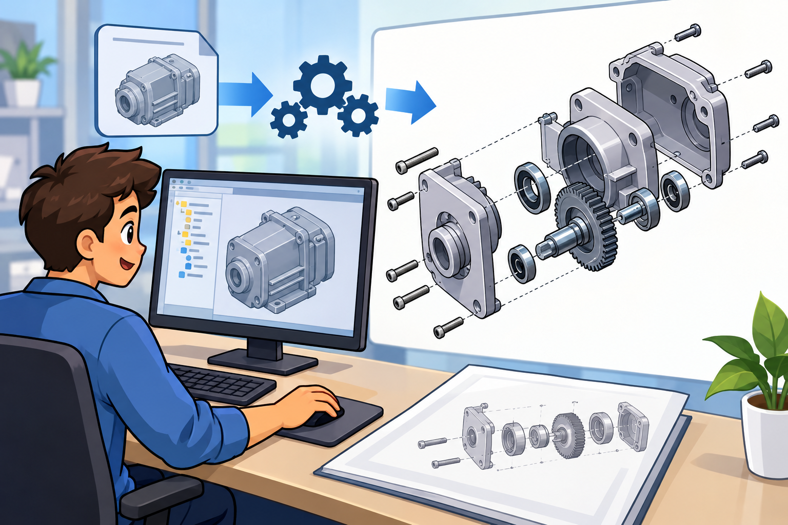
Automated exploded views rely on the fact that modern assemblies are not merely collections of shapes. They contain hierarchy, constraints, mates, coordinate systems, named features, component patterns, subassemblies, configuration states, and part-level information that can be interpreted by software. When a designer builds a gearbox, surgical instrument, consumer device, or machine enclosure, the assembly tree already expresses many useful relationships: which components belong together, which fasteners attach which plates, which seals sit between housings, and which modules are replaceable as service units. Advanced documentation tools use this information to generate controlled component separation without forcing the illustrator to manually drag every part into place. The system can separate a cover from a base, fan out repeated fasteners, preserve subassembly grouping, and maintain orientation relative to the assembled product. This is where **automated exploded views** become more than a convenience feature. They convert product structure into visual logic. Instead of asking an illustrator to infer every relationship from geometry, the software uses the assembly as a source of semantic information, substantially reducing repetitive interpretation and increasing consistency across manuals, catalogs, and training assets.
Collision-free spacing and disassembly logic
The most advanced automation is not limited to moving parts outward in arbitrary directions. Useful exploded views must describe plausible disassembly, not simply display a decorative separation of components. Software can evaluate bounding boxes, contact relationships, fastener axes, insertion directions, and mate constraints to infer how components are likely to be removed. A screw should typically travel along its axis, a sliding cover should move along its rail direction, and a circuit board should clear connectors before rotating. Intelligent spacing also matters because crowded exploded diagrams often become harder to understand than assembled views. Rule-based tools can maintain minimum visual gaps, avoid component overlap in the camera view, and route parts along paths that do not pass through surrounding geometry. In engineering documentation, this capacity supports both visual clarity and procedural accuracy. When a part is exploded in the same direction it is actually removed, technicians develop better spatial intuition. When the diagram avoids collisions and preserves logical order, the illustration becomes an operational guide rather than a stylized image. This distinction is essential for documentation that supports maintenance, field repair, installation, and regulated product handling.
- Automatic part separation can follow assembly hierarchy, service grouping, or manufacturing sequence.
- Intelligent spacing can reduce overlap, preserve readability, and improve visual balance.
- Collision-free disassembly paths can reflect plausible removal directions instead of arbitrary offsets.
- Subassembly preservation can keep functional modules visually grouped while exposing internal structure only when needed.
Callouts, BOM references, and reusable documentation templates
One of the most labor-intensive parts of technical illustration is not the view itself but the surrounding information system: balloons, leader lines, item numbers, part names, bill of materials references, notes, warnings, and procedural labels. Modern documentation software can automate a large portion of this work by connecting callouts directly to model metadata and BOM records. When a component is selected, the software can retrieve its part number, description, material, quantity, supplier identifier, revision, or lifecycle state. The resulting callouts can be generated according to company standards, regional formatting requirements, or publication type. A service manual may emphasize replaceable units and torque values, while a spare parts catalog may prioritize orderable assemblies and item numbers. Reusable templates help standardize these outputs so that every product line does not require a unique documentation style. Templates can define camera projection, line weight, shaded or vector rendering, balloon placement behavior, table formatting, warning symbol placement, and multilingual text fields. The strong advantage is consistency: once a documentation rule is approved, it can be applied repeatedly across installation guides, assembly instructions, maintenance documents, and web-based product support assets.
Model updates and associative illustration behavior
The most valuable feature of model-connected documentation is not the first automated view; it is the ability to respond intelligently when the product changes. Engineering models evolve continuously. Holes move, brackets are consolidated, fastener counts change, materials are substituted, and purchased components are replaced because of supply chain realities. In a disconnected workflow, each of these changes requires someone to discover the impact on published materials. In an associative workflow, the documentation environment can compare the current model to the version used in the existing illustration and flag differences. A removed part can trigger a missing callout warning. A changed component identifier can update a parts table. A modified geometry can refresh the visual representation while retaining the author’s selected camera angle and annotation intent. This form of associativity is a practical expression of the **digital thread**, because the documentation no longer sits outside product development. It becomes a managed derivative that can be updated, validated, and released alongside engineering revisions. For organizations that produce frequent product variants, configurable equipment, or regional adaptations, this link can dramatically reduce the burden of keeping manuals synchronized with reality.
The role of AI and rule-based automation
Rule-based automation and artificial intelligence are beginning to expand what documentation software can infer from complex assemblies. Rules are powerful when organizations have consistent design conventions: for example, fasteners along a common axis can be removed first, safety covers can be shown before internal service parts, and electrical connectors can receive warning labels when voltage metadata exceeds a threshold. AI adds a complementary layer by detecting patterns that are harder to encode manually. It may recognize that a cluster of components forms a removable module, suggest a camera angle that reveals hidden fasteners, identify parts that are visually obstructed, or propose a step-by-step sequence based on part relationships and historical authoring behavior. The goal is not to turn documentation into a black box but to provide intelligent suggestions that accelerate expert review. A documentation specialist may accept, modify, or reject software-generated sequences, maintaining editorial control while avoiding repetitive setup. Over time, these systems can become increasingly useful as they learn organizational preferences for exploded distance, callout density, view orientation, safety emphasis, and service sequence logic.
- AI can suggest logical disassembly sequences based on mates, fasteners, access direction, and replaceable modules.
- Camera recommendation tools can prioritize visibility of hidden components and readable part separation.
- Automated checks can detect missing fasteners, unreferenced parts, duplicate balloons, or obscured components.
- Instruction-generation tools can convert assembly structure into preliminary visual steps for expert refinement.
Technical Documentation as a Connected Digital Asset
Integration with PLM, PDM, and service systems
As documentation becomes model-driven, it also becomes a connected digital asset within the broader product information ecosystem. Product lifecycle management and product data management systems already govern engineering revisions, release states, permissions, configurations, and approval processes. When documentation tools connect to these systems, the manual is no longer a loose file assembled at the end of development. It can reference controlled product structures, approved revisions, validated bills of materials, and service-specific configurations. This matters because the same physical product may exist in multiple variants depending on region, customer, production date, or regulatory requirement. A documentation environment connected to PLM can generate the correct illustration for a specific configuration rather than forcing authors to manually track which view belongs to which variant. Service platforms extend this value further by connecting the published output to equipment records, repair procedures, technician work orders, and spare parts ordering. In this context, a technical illustration is not just explanatory media. It becomes a navigable interface into product knowledge, helping users move from visual identification to procedure, part procurement, compliance information, and feedback from the field.
Why metadata is becoming central to illustration
Geometry shows what a product looks like, but metadata explains what the product means. In older workflows, much of this information lived separately in spreadsheets, ERP systems, engineering notes, or service databases. Automated documentation makes metadata central because the visual output can only be as intelligent as the data behind it. A part number connects a visual component to purchasing and replacement. A revision history clarifies whether a procedure applies to a current or obsolete design. Material data may determine whether a component requires special handling, corrosion precautions, sterilization requirements, or recycling instructions. Torque values connect fasteners to assembly quality and safety. Service intervals determine when maintenance actions should appear in a technician portal. Safety warnings ensure that visual instructions communicate risks, not just geometry. When this information is embedded, linked, or reliably retrieved, the illustration can deliver context-sensitive guidance. For example, selecting a fastener in an interactive service view could display its tool size, tightening torque, thread-locking requirement, replacement rule, and related warning. This is the difference between a picture with labels and a **structured product knowledge asset**.
- Part numbers and descriptions connect visual components to procurement, inventory, and spare part fulfillment.
- Revision history helps ensure that manuals match the correct engineering release or product configuration.
- Material and compliance data support handling, recycling, sterilization, and regulatory communication.
- Torque values, service intervals, and safety warnings turn illustrations into actionable maintenance guidance.
Single-source publishing across many outputs
One of the strongest arguments for automated documentation is the ability to publish many formats from a single maintained source. A printed manual, an interactive PDF, a web portal, an augmented reality repair sequence, a training animation, and a spare parts catalog may all require the same underlying product structure, but each format presents it differently. In a traditional workflow, these outputs are often recreated independently, leading to duplicated effort and conflicting information. In a connected workflow, the assembly model, metadata, exploded states, callouts, and procedural steps can be stored as reusable information objects. A print output may flatten the view into vector line art with numbered balloons. A web portal may expose the same view as a rotatable 3D scene with selectable components. An AR application may use the same disassembly sequence to overlay directional arrows onto physical equipment. A training animation may convert exploded positions into motion paths and timed instructional beats. The core principle is single-source control: update the product information once, validate it once, then publish it through multiple channels with formatting appropriate to each audience and device.
Interactive and immersive documentation experiences
The movement from static images to interactive documentation changes how technicians, assemblers, customers, and trainees engage with product information. A static exploded view is useful because it compresses spatial relationships into a single readable image, but it also forces the viewer to interpret depth, order, and hidden geometry. Interactive documentation can remove that ambiguity. Users can rotate a model, isolate a subassembly, filter by service step, hide already removed parts, search by part number, or select a component to reveal related warnings and tools. In augmented reality workflows, the documentation can be registered to the physical product so that removal directions, fastener locations, and safety zones appear directly in the technician’s field of view. This does not mean every manual should become immersive; many tasks are still best served by concise diagrams and printed references. However, for complex service operations, limited-access components, high-value machinery, or products requiring specialized training, interactive views can reduce cognitive load. The key design challenge is restraint. The best systems do not overwhelm users with 3D novelty; they reveal the right information at the exact moment it improves comprehension, accuracy, or confidence.
Industry value in complex product environments
The benefits of automated illustration are most visible in industries where products are complex, tightly regulated, frequently revised, or expensive to service. Aerospace documentation must manage large assemblies, strict configuration control, long service lives, and precise maintenance procedures. Automotive organizations need scalable documentation for platforms, trims, regional variants, and rapidly evolving electrified systems. Industrial machinery manufacturers must support installation, commissioning, repair, retrofitting, and spare part ordering across global service networks. Medical device companies require documentation that aligns with quality systems, safety warnings, sterilization instructions, and controlled design history. Consumer electronics teams face short product cycles, compact assemblies, delicate components, and high demand for clear repair or support material. Across these sectors, the value is not only speed. It is quality, traceability, and repeatability. A technician replacing a module in a factory, a repair specialist servicing compact electronics, and a manufacturing engineer validating an assembly process all benefit when the visual instruction reflects the correct version of the product. Automated documentation supports this by connecting the visual layer to controlled engineering data rather than relying on manually maintained representations.
- Aerospace benefits from configuration-specific documentation and rigorous revision traceability.
- Automotive teams benefit from scalable outputs across vehicle platforms, trims, and regional variants.
- Industrial machinery manufacturers benefit from clearer service, installation, and spare parts communication.
- Medical device organizations benefit from controlled documentation aligned with safety and quality requirements.
- Consumer electronics teams benefit from faster updates and clearer communication for compact, intricate assemblies.
Design Process Implications for Engineering and Documentation Teams
Changing responsibilities across disciplines
Automated illustration changes the relationship between engineering, documentation, manufacturing, and service teams. In a manual workflow, documentation often receives engineering data late and must compensate for incomplete naming conventions, inconsistent assembly structure, missing metadata, and ambiguous service intent. In a model-driven workflow, those upstream decisions directly affect the quality of downstream communication. A clean assembly tree, meaningful part names, stable identifiers, service-aware grouping, and accurate metadata become documentation enablers. This creates a strong incentive for design teams to model not only for manufacturing but also for communication. Engineers may need to identify replaceable modules, define removal directions, attach torque data, or structure assemblies in ways that reflect service reality. Documentation specialists, in turn, become more involved in defining rules, templates, publication logic, and validation criteria. The process becomes collaborative rather than sequential. The best results occur when technical illustrators are not treated as people who merely “make pictures,” but as experts in visual product intelligence who help configure the rules by which engineering data becomes reliable instruction.
Model quality and documentation readiness
The promise of automation depends heavily on the quality of source data. A poorly structured CAD assembly can still generate an exploded view, but it may produce confusing separation, incorrect grouping, or excessive manual cleanup. Documentation readiness therefore becomes an important design maturity criterion. Components should have stable part identifiers, subassemblies should reflect functional or service groupings where possible, and fasteners should be modeled or represented in a way that supports accurate callouts. Lightweight or simplified geometry should be managed carefully so that visual output remains clear without misrepresenting critical details. Metadata should be maintained through controlled fields rather than informal notes buried in file names or drawings. Design teams may also need to define which product configurations are documentation-relevant, because publishing every engineering variant can create unnecessary complexity. This is where governance matters. Automated documentation is not magic; it is a system that rewards disciplined data management. When CAD, PDM, PLM, and documentation tools share consistent information structures, teams can generate outputs faster and trust them more. When source data is inconsistent, automation may simply expose the disorder more visibly.
- Use meaningful component names and stable identifiers rather than temporary or ambiguous labels.
- Structure assemblies to reflect functional, manufacturing, or service relationships where appropriate.
- Maintain metadata such as torque values, materials, revision states, and safety notes in controlled fields.
- Define documentation-relevant configurations to avoid publishing unnecessary or misleading variants.
Validation as a critical layer of automation
As documentation becomes more automated, validation becomes more important, not less. The fact that a view can be generated automatically does not guarantee that it communicates correctly. Software may know that two parts are connected, but it may not understand a technician’s preferred access strategy, a regulatory requirement, or a shop-floor convention unless those rules have been encoded or reviewed. Effective workflows include validation checkpoints that compare generated documentation against engineering release data, service requirements, safety standards, and usability expectations. Automated checks can find missing balloons, unreferenced parts, out-of-date revisions, overlapping callouts, hidden fasteners, incomplete BOM links, and inconsistent terminology. Human reviewers then focus on judgment: Is the sequence understandable? Does the viewpoint reduce ambiguity? Are warnings placed at the right moment? Does the illustration include too much detail for the intended task? This balance is essential. Automation should remove mechanical effort while strengthening expert review. A mature documentation pipeline therefore combines associative updates, metadata checks, publication rules, and human approval workflows, producing outputs that are not only faster but also more trustworthy.
The Future Is Intelligent, Interactive, and Always Up to Date
From static communication to connected product knowledge
The central shift in technical illustration is the movement from static visual communication to intelligent, connected product knowledge. Exploded views were once created as finished drawings that explained an object at a specific moment. Increasingly, they are generated views of a living product definition, capable of updating as parts change, metadata evolves, and service requirements become more refined. This makes automated exploded views far more significant than a productivity feature. They are becoming part of the broader digital thread that connects design, manufacturing, quality, documentation, training, and service. When the same engineering data can drive assembly instruction, maintenance guidance, spare part identification, and interactive training, organizations reduce duplication and improve alignment. The long-term benefit is not merely faster publishing, although speed is important. The deeper benefit is that product knowledge becomes reusable and consistent across the lifecycle. A single corrected part number, warning, or disassembly step can propagate into every relevant output instead of being manually corrected in scattered documents. This is the foundation for documentation that remains current by design rather than by crisis-driven revision.
Long-term operational implications
The operational implications are substantial. Faster documentation cycles allow manufacturers to release products, variants, and updates without waiting for extensive manual illustration work. Fewer service errors result when technicians receive configuration-specific instructions with accurate callouts, current warnings, and visually clear disassembly steps. Manufacturing and maintenance communication improves when the same product structure supports both assembly planning and field repair. Engineering data reuse improves because the model, metadata, and product hierarchy become assets that serve multiple downstream functions instead of remaining locked inside CAD and PLM environments. Customer and technician experiences become more consistent because every output can be generated from governed information rather than from separately maintained files. These benefits compound over time. Organizations that invest in structured data, automation rules, and connected publication pipelines gradually build documentation systems that become faster and more reliable with each product generation. The future manual will not be a static endpoint. It will be a continuously updated product interface, capable of being generated, validated, localized, personalized, and republished as the underlying design evolves.
- Faster documentation cycles reduce delays between engineering release and usable support material.
- Fewer service errors result from accurate sequences, current revisions, and clearer visual guidance.
- Better manufacturing and maintenance communication emerges when both teams reference connected product data.
- Improved reuse of engineering data turns CAD and metadata into lifecycle communication assets.
- More consistent technician and customer experiences come from single-source, governed publication workflows.
Generated, validated, localized, and continuously updated
The next generation of technical documentation will be increasingly automatic in the full sense of the word: generated from controlled product data, validated against rules and metadata, localized for language and regional requirements, and updated whenever the product changes. AI will assist by proposing sequences, identifying missing information, simplifying views, and adapting instructions to user context. Rule engines will enforce standards for safety, formatting, terminology, and publication. Connected platforms will distribute the right documentation to the right user based on product configuration, serial number, service history, or training level. This future does not remove the need for expert communicators, engineers, or service specialists; it raises the importance of their judgment by freeing them from repetitive reconstruction. The most successful organizations will treat documentation as a strategic layer of the product lifecycle, not as an afterthought. Automated exploded views are an early and highly visible sign of that transformation. They show how design data can become instruction, how instruction can become interactive experience, and how product knowledge can remain synchronized with the object it describes.
Also in Design News