Your Cart is Empty


Design Software History: Design for Additive Manufacturing: How 3D Printing Reshaped CAD and Solid Modeling


From Printable Geometry to a New Design Discipline
The Early CAD Assumption
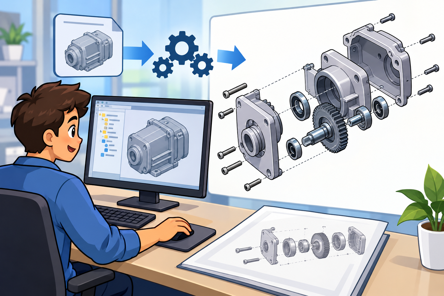
In the first decades of commercial 3D printing, most CAD systems treated additive manufacturing as an output destination, not as a fundamentally different design method. Engineers created parts in the same solid-modeling tools they used for machining, casting, molding, or sheet-metal fabrication, then exported a file for a separate preparation workflow. A designer working in systems such as Pro/ENGINEER from Parametric Technology Corporation, CATIA from Dassault Systèmes, Unigraphics from EDS and later Siemens, or SolidWorks in the 1990s and early 2000s generally thought in terms of sketches, extrusions, revolves, fillets, shells, holes, ribs, bosses, and assemblies. Once the design was considered complete, the model was often translated into an STL mesh and sent to another application for repair, slicing, support generation, and machine setup. This workflow made sense historically because early stereolithography, selective laser sintering, and fused deposition systems were still viewed as prototyping machines. The central objective was to get a shape out of CAD and into the physical world, even if that shape was still conceived according to conventional manufacturing habits.
The STL Bridge and Its Hidden Cost
The STL format, developed by 3D Systems in the late 1980s during the rise of Chuck Hull’s stereolithography technology, became the practical bridge between CAD software and the first generation of commercial additive machines. Its genius was its simplicity: a CAD model could be tessellated into a collection of triangular facets, and those facets defined the approximate surface of the part. Yet that same simplicity created long-term limitations that shaped the history of Design for Additive Manufacturing. STL discarded feature history, analytic surfaces, constraints, color, material definitions, tolerances, and most forms of engineering metadata. It also introduced unit ambiguity, because the format did not reliably encode whether a dimension was in millimeters, inches, or another unit. Curved surfaces became faceted approximations, and model repair became a persistent industry problem. Companies such as Materialise built important software businesses around fixing, preparing, and managing mesh data precisely because the CAD-to-printer bridge was so lossy. STL helped additive manufacturing grow, but it also delayed the realization that additive manufacturing needed design intelligence inside CAD itself.
Printable Did Not Mean Optimized
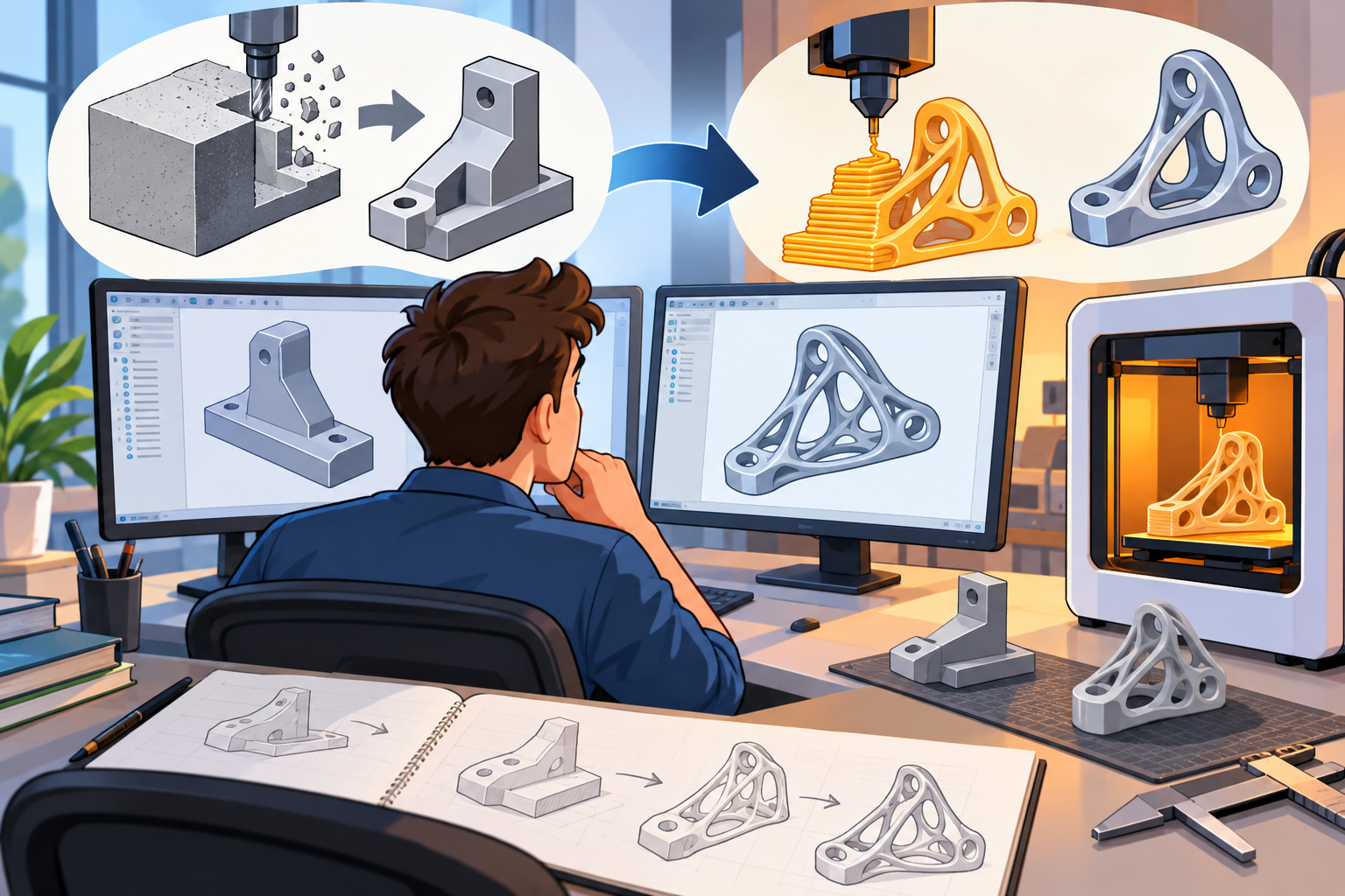
The weakness of early workflows was not that they failed to produce physical parts. They often succeeded at that basic task. The deeper problem was that they produced parts designed with old assumptions embedded in them. A bracket might be exported to STL and printed successfully, but it would still have the silhouette, ribbing logic, wall thicknesses, and stress paths of a machined or cast component. Conventional CAD encouraged designers to think in prismatic cuts, planar faces, draft angles, tool access, mold parting lines, and assembly sequences. Those concerns remained relevant for traditional manufacturing, but additive manufacturing opened a different design space. Internal channels no drill could reach, material placed only along load paths, monolithic replacements for multi-part assemblies, and geometry tuned to thermal or biological performance all challenged the old feature-centered approach. The historical turning point came when software vendors, researchers, and advanced manufacturers recognized that DfAM was not merely downstream print preparation. It was a new design discipline requiring CAD systems to represent, evaluate, and generate forms that were never intended for subtractive manufacturing.
- Early workflow: CAD model, STL export, mesh repair, slicing, supports, build preparation.
- Hidden limitation: the design intent usually remained conventional even when the manufacturing method was additive.
- Historical shift: DfAM moved additive thinking from printer software back into the design environment.
The Technologies That Forced CAD to Change
Additive Manufacturing Challenged Solid Modeling Assumptions
Traditional solid modeling was built around the representation of enclosed volumes, usually using boundary representation, or B-rep, geometry supported by analytic surfaces such as planes, cylinders, cones, spheres, and NURBS patches. Kernels such as Parasolid, originally developed by Shape Data and later owned by Siemens, and ACIS, developed by Spatial Technology and later owned by Dassault Systèmes, were exceptionally powerful for mechanical design because they supported precise topology, Boolean operations, filleting, shelling, and parametric feature histories. Additive manufacturing did not invalidate those capabilities, but it exposed their limits. A B-rep model is excellent for describing a machined housing with holes and mounting bosses; it becomes less comfortable when asked to describe millions of lattice struts, stochastic cellular networks, graded porosity, complex trabecular structures, or organic load-path forms generated by optimization. CAD kernels were designed for clarity, precision, and editability, not necessarily for vast fields of small repeating geometry. As additive manufacturing moved from prototyping into aerospace, medical implants, motorsport, energy systems, and industrial tooling, CAD had to expand beyond traditional surface-and-solid definitions into mesh, voxel, field, and implicit methods.
New Geometries Changed the Software Agenda
The manufacturing capabilities of additive processes changed the questions software had to answer. Laser powder bed fusion could produce complex metal parts with internal ducts for cooling, fuel flow, or hydraulic routing. Polymer powder bed fusion could support intricate lattice cushioning and lightweight structures. Vat photopolymerization could create fine surface detail, dental devices, and anatomical models. Directed energy deposition introduced repair and hybrid manufacturing possibilities. Binder jetting promised scalable metal and sand applications. Each process placed different demands on the design tool, but all shared a key effect: they weakened the old assumption that manufacturability meant tool access. Once a feature no longer needed an end mill, drill, mold core, or assembly fixture to reach it, CAD users began asking for geometry that followed flow, stress, heat, acoustics, mass, and personalization. The software response could not be limited to a print button. Designers needed build orientation feedback, support-risk analysis, residual stress prediction, surface-quality estimation, powder-removal planning, and ways to design internal features without losing control of the model’s engineering purpose.
- Curved internal channels for cooling, fluid flow, and heat exchangers.
- Lightweight lattice structures and cellular materials that reduce mass while preserving stiffness.
- Organic shapes from optimization that place material where load paths demand it.
- Part consolidation that replaces fasteners, welds, and assemblies with single printed components.
- Mass customization in dental, orthopedic, consumer, and ergonomic products.
- Multi-material and functionally graded designs where material behavior varies across the part.
Topology Optimization Became a Practical Design Driver
Topology optimization did not originate with commercial 3D printing. Its intellectual roots extend through structural optimization research in applied mechanics, finite element analysis, and mathematical programming, with influential academic work from researchers such as Martin P. Bendsøe and Noboru Kikuchi in the late twentieth century. For years, topology optimization was valuable but awkward: the resulting forms were often difficult to manufacture using milling, casting, or molding without major reinterpretation. Additive manufacturing changed that balance. Suddenly, the branching, bone-like, and highly organic forms produced by optimization algorithms were not just theoretical suggestions; many could be printed directly or redesigned with far less compromise. This is why companies such as Altair, with OptiStruct and Inspire, became so influential in additive-oriented design. Autodesk invested heavily in generative design inside Fusion 360 and earlier research platforms. Dassault Systèmes connected SIMULIA, CATIA, and 3DEXPERIENCE workflows. Siemens integrated optimization and simulation into NX. PTC added additive and generative capabilities to Creo. The importance of topology optimization was historical as much as technical: it shifted the designer’s role from manually sculpting every feature to defining constraints, loads, objectives, materials, and manufacturing processes.
Lattices Pushed CAD Beyond Ordinary Geometry
Lattice and cellular structures presented one of the clearest software challenges in DfAM. A conventional CAD system might handle a few dozen ribs or holes without trouble, but a production lattice can contain hundreds of thousands or millions of beams, nodes, cells, and transitions. If every strut is represented as a precise B-rep cylinder with trimmed surfaces, edges, vertices, and feature dependencies, the model can become unusably heavy. This forced the industry to take mesh-based and implicit modeling seriously. In implicit modeling, geometry can be represented as a mathematical field, often by defining a surface as the location where a function reaches a particular value. This approach is naturally suited to smooth blends, graded lattices, gyroid structures, and field-driven variation. nTopology became one of the most important companies associated with this shift, because it rejected the assumption that every design had to be built as a classical feature tree. Its field-driven approach allowed engineers to vary thickness, porosity, stiffness, or pattern density according to stress, distance, temperature, or other simulation-derived values. This was a major conceptual step toward computational design rather than merely digital drafting.
How CAD Platforms Absorbed DfAM
From Specialist Print Tools to Mainstream CAD
DfAM entered mainstream CAD gradually, through a combination of acquisition, integration, and competitive repositioning. For many years, additive manufacturing preparation lived in specialist tools. Materialise Magics became a central application for mesh repair, support generation, nesting, labeling, build preparation, and service-bureau workflows. Netfabb, founded in Germany and later acquired by Autodesk, became another important platform for file repair, analysis, and additive manufacturing preparation. These products existed because mainstream CAD did not yet handle the practical realities of printing well enough. Over time, however, the boundary between CAD and print preparation blurred. Designers did not want to discover support problems, trapped powder, thermal distortion, or lattice failures after releasing geometry downstream. They needed additive feedback while the model was still fluid. This pressure encouraged CAD vendors to absorb functions once considered external utilities. Printability checks, build orientation studies, lightweighting tools, lattice generators, machine-specific constraints, and simulation loops began appearing inside or adjacent to the CAD environment. The CAD model was no longer the final design artifact; it became one node in a connected manufacturing workflow.
The New Toolset Inside CAD
The absorption of DfAM changed the functional definition of a CAD platform. A mature additive-aware CAD environment had to do more than create watertight solids. It had to evaluate whether a design would print, distort, overheat, collapse under support removal, trap powder, exceed machine build volume, or fail because of anisotropic material behavior. Support generation, once treated as a printer-software task, became a design consideration because supports affect surface finish, cost, post-processing access, and even whether a part can be removed from a build plate without damage. Build orientation ceased to be a technician’s afterthought and became a design variable tied to strength, accuracy, surface quality, recoater risk, and support volume. Likewise, simulation had to become more process-aware. Traditional finite element analysis evaluated the service performance of a part after manufacture; additive simulation also had to estimate manufacturing-induced residual stress, warpage, thermal gradients, microstructure effects, and layerwise process behavior. These additions transformed CAD from a geometric authoring system into a design-manufacturing decision environment.
- Built-in printability checks for wall thickness, overhangs, enclosed voids, and minimum feature size.
- Support generation and support-avoidance strategies linked to design choices.
- Build orientation analysis tied to cost, accuracy, strength, and surface finish.
- Lattice-design tools for lightweight structures, cushioning, implants, and thermal control.
- Topology optimization and generative design workflows connected to simulation.
- Distortion, residual stress, and thermal simulation for process-aware validation.
- Direct export or connection to machine preparation and production management environments.
Autodesk and the Push Toward Unified Workflows
Autodesk played a visible role in popularizing the idea that additive manufacturing belonged inside a broader, unified design-to-manufacturing workflow. Its acquisition of Netfabb in 2015 gave Autodesk deeper technology for mesh repair, additive preparation, support strategies, and industrial build workflows. Fusion 360 then became a public-facing expression of a larger strategy: combine CAD, CAM, CAE, collaboration, generative design, and manufacturing planning in one cloud-connected environment. Autodesk had already explored advanced fabrication research through projects such as Within, a company known for lattice and optimization capabilities that Autodesk also acquired, and through generative design efforts associated with Autodesk Research. The company’s generative design tools were significant because they helped make additive-friendly organic forms familiar to a larger audience of engineers and product designers. Instead of starting with a block and cutting material away in the mental style of machining, users could define keep-out zones, load conditions, materials, safety factors, and manufacturing methods. The software then generated alternatives, many of which visibly reflected the freedom offered by additive manufacturing.
Siemens, Dassault Systèmes, and Industrial-Scale Additive Integration
Siemens and Dassault Systèmes approached DfAM with the weight of long-standing industrial CAD, PLM, and simulation ecosystems. Siemens NX, built on a lineage that includes Unigraphics and the Parasolid kernel, integrated additive manufacturing tools with high-end modeling, simulation, CAM, robotics, and manufacturing planning. This mattered especially for aerospace, turbomachinery, medical, and industrial machinery customers who needed additive capability inside controlled engineering environments rather than isolated experimental tools. Siemens also connected additive workflows to Teamcenter PLM, reflecting the reality that production additive parts require revision control, material traceability, machine parameters, inspection plans, and certification documentation. Dassault Systèmes used CATIA, SIMULIA, DELMIA, and the 3DEXPERIENCE platform to position additive manufacturing as part of a lifecycle environment rather than a single modeling feature. CATIA’s strength in complex surfaces and aerospace-grade engineering made it relevant for highly engineered printed components, while SIMULIA brought advanced simulation into the workflow. In both companies’ strategies, DfAM was not just about geometry creation; it became a bridge between design intent, process planning, validation, and enterprise manufacturing governance.
Startups, Specialists, and Machine Ecosystems
Startups and specialist companies often moved faster than large CAD vendors because they were less constrained by legacy feature trees and traditional modeling expectations. nTopology, founded in 2015, became especially important because its implicit and field-driven modeling system addressed the kinds of geometries that classical parametric CAD struggled to manage. Materialise continued to be influential through Magics and its broader additive manufacturing services, particularly in medical, orthopedic, industrial, and service-bureau workflows where data preparation, traceability, and reliability are essential. Machine vendors also shaped software requirements. EOS influenced metal powder bed fusion workflows through industrial laser systems. Stratasys shaped polymer additive practice through FDM and PolyJet ecosystems. 3D Systems remained historically central because of stereolithography and broad additive technologies. Formlabs helped normalize professional desktop stereolithography and selective laser sintering workflows. Carbon pushed software-linked digital light synthesis and material-process integration. Desktop Metal emphasized binder jetting and production-oriented metal additive manufacturing. Each machine ecosystem created software demands around materials, supports, orientation, compensation, nesting, validation, and production data, proving that DfAM could not be separated from machine reality.
DfAM Changed What CAD Was Supposed to Be
From Describing Parts to Exploring Possibilities
The central historical shift is that early CAD helped engineers describe parts, while DfAM-era CAD helps engineers explore what parts could become when manufacturing limits are different. Drawing-centered systems translated drafting practices into software. Feature-centered solid modeling translated machining, casting, and assembly logic into editable digital geometry. DfAM introduced a third orientation: performance-centered design. In this mode, the designer still cares about geometry, but geometry is no longer the starting assumption. The process begins with loads, constraints, heat flow, fluid movement, stiffness targets, weight limits, cost limits, machine envelope, support strategy, surface requirements, and material behavior. The resulting form may be prismatic, organic, latticed, porous, cellular, consolidated, or customized. This does not mean traditional CAD disappeared. Precise B-rep modeling remains essential for interfaces, sealing surfaces, datum structures, fastening points, and regulated engineering documentation. But additive manufacturing forced CAD to broaden its identity. A modern CAD platform can no longer be understood only as a digital tool for drawing solids. It increasingly operates as a computational environment where design intent, analysis, and manufacturing feedback continuously interact.
The Deep Changes Beneath the Interface
Additive manufacturing did not simply add another export option to CAD. It forced software vendors to revisit foundational assumptions about geometry representation, simulation integration, material awareness, and manufacturing feedback. Meshes, once treated as degraded export artifacts, became active design representations. Implicit models, once mostly associated with research and specialized computation, became practical tools for lattices, smooth blends, and field-driven structures. Simulation moved earlier in the workflow, not as a final verification step but as a generator of design direction. Materials became more complex because printed properties depend on orientation, process parameters, post-processing, porosity, and microstructure. Manufacturing constraints became richer, not weaker. Additive manufacturing removed some traditional limitations, but it introduced new ones: overhang angles, support scars, trapped powder, residual stress, anisotropy, build failures, recoater interference, heat accumulation, and qualification requirements. This is why the most serious DfAM tools do not celebrate freedom without discipline. They combine geometric freedom with process knowledge. The result is a more honest form of design software, one that acknowledges that geometry, material, machine, and performance are inseparable in advanced manufacturing.
- Geometry representation expanded beyond classical solids into mesh, lattice, voxel, and implicit structures.
- Simulation integration moved from late-stage checking toward early-stage design generation.
- Material awareness became essential because printed performance depends on process and orientation.
- Manufacturing feedback entered the design phase through printability, support, and distortion analysis.
- Optimization-driven design changed how engineers define and evaluate form.
The Broader Legacy of DfAM
The most important legacy of DfAM may not be any single 3D-printed bracket, turbine component, medical implant, heat exchanger, or lattice-filled aerospace part. Its deeper impact is that it changed expectations for CAD itself. Engineers and designers now increasingly expect software to propose, analyze, adapt, and connect, not merely document. The rise of additive manufacturing made it harder to maintain a clean separation between design software and manufacturing software, because the manufacturability of a printed part is embedded in geometry, orientation, support strategy, material behavior, and process parameters from the beginning. This historical transformation also made CAD more mathematical and more computational. The industry moved from drafting entities to parametric features, from parametric features to simulation-informed structures, and from simulation-informed structures to field-based and optimization-driven design. The companies that shaped this transition—Autodesk, Siemens, Dassault Systèmes, PTC, Altair, Materialise, nTopology, 3D Systems, Stratasys, EOS, Carbon, Formlabs, and others—did not merely add additive checkboxes to existing tools. Collectively, they helped redefine CAD as a manufacturing-aware design environment. DfAM made CAD behave less like a digital drafting table and more like a computational partner connected directly to manufacturing reality.
Also in Design News