
Your Cart is Empty


Mesh-to-CAD Reverse Engineering in Modern Design Software
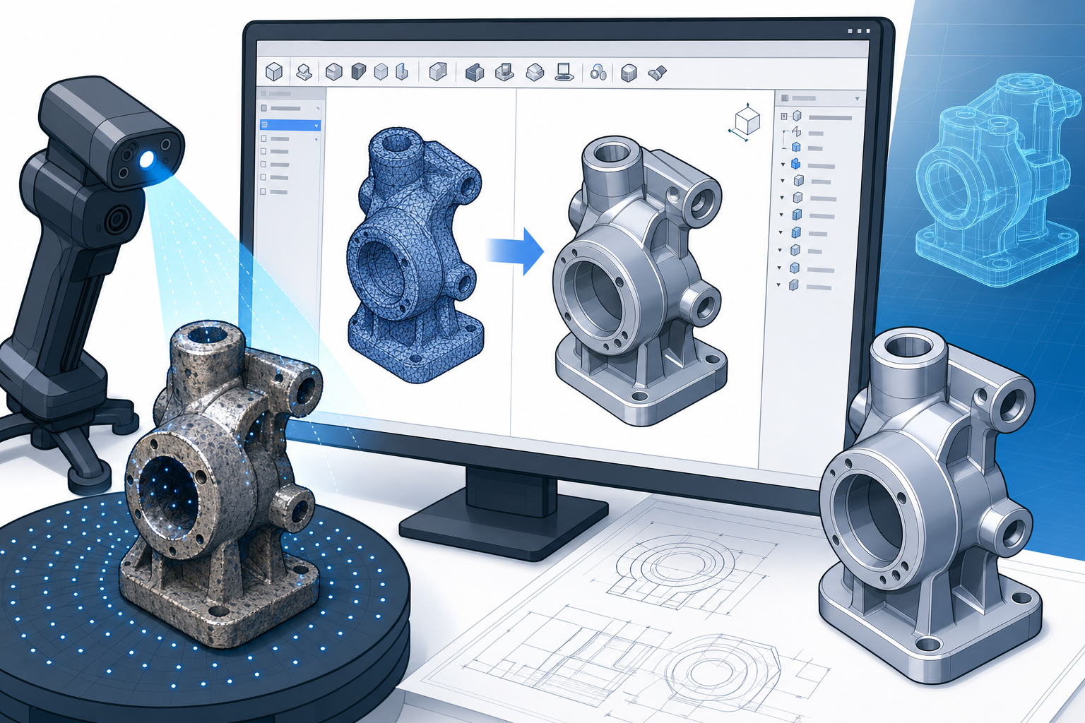


The New Starting Point for Digital Design
Captured Geometry Has Entered the Mainstream
Design teams are no longer beginning every project with a blank sketch plane and a clean parametric feature tree. Increasingly, the first input is a scanned component, a tessellated STL from an additive manufacturing workflow, a supplier OBJ file, a drone-captured building envelope, or a field measurement dataset from a mobile scanner. This shift matters because these inputs are not merely visual references; they often represent the only available source of truth for a physical object, legacy assembly, replacement part, or built environment. The practical design challenge is that captured geometry arrives with the messiness of reality: worn edges, manufacturing deviations, missing areas, surface noise, inconsistent scale, and no embedded design intent. Traditional CAD was built around idealized solids, constrained sketches, and mathematically clean surfaces. Modern CAD must now operate in a different world, where imported meshes and scan data are fundamental engineering inputs rather than awkward external files to be redrawn from scratch.
Why Meshes Are Now Core CAD Inputs
Real Products Rarely Arrive as Perfect Parametric Models
The growing importance of mesh-based workflows is closely tied to the realities of contemporary product development. Companies inherit old products with no usable CAD history, update manufactured parts that have drifted from original drawings, receive supplier geometry in lightweight tessellated formats, and inspect 3D printed prototypes that differ subtly from nominal designs. In architecture and construction, teams increasingly capture existing conditions using laser scanners, drones, and mobile devices, then need to convert that reality data into actionable geometry for renovation, fabrication, or facility documentation. In medical, automotive, aerospace, and industrial equipment environments, designers often work from physical objects whose final form was shaped by casting, machining, wear, ergonomic testing, or manual fabrication. These contexts make reverse engineering a normal design function, not a specialized exception. The key insight is that a mesh is not automatically inferior to CAD; it is simply a different representation. It captures shape through triangles, while CAD describes shape through analytic surfaces, topology, constraints, and feature relationships.
- 3D scans capture real-world geometry that may not match nominal drawings.
- STL and OBJ files commonly appear in additive manufacturing and visualization pipelines.
- Legacy parts may exist physically but lack editable CAD models.
- Supplier geometry may be delivered as lightweight faceted data for speed or IP protection.
- Reality capture from buildings, infrastructure, and equipment creates large spatial datasets for design reference.
The Fundamental Gap Between Captured Shape and Editable Intent
Triangles Describe Form, But Not Engineering Logic
The central difficulty with imported meshes is not that they are visually inaccurate; many scans can represent physical form with impressive fidelity. The difficulty is that meshes lack the semantic structure that engineering software expects. A cylindrical boss in a scan is not recognized automatically as a cylinder with a diameter, axis, concentric constraint, and manufacturing purpose. It is usually thousands of triangles arranged in a roughly cylindrical pattern, potentially interrupted by noise, scratches, holes, or scanning shadows. A flat mounting face is not a plane in the CAD sense; it is a cloud of small facets that approximate flatness within measurement tolerance. This distinction affects everything downstream, including dimensioning, tolerance analysis, simulation, tooling design, and manufacturing preparation. The goal of reverse engineering is therefore not simply to “convert STL to CAD,” because conversion alone may produce a heavy, uneditable object. The higher-value goal is to recover design intent where it matters, preserve organic form where parametrics are unnecessary, and create a model that behaves appropriately for the next engineering task.
The Raw Scan Problem
Why Imported Data Usually Needs Interpretation
Raw scan data is often persuasive on screen but unreliable as a direct engineering foundation. Holes appear where the scanner could not see undercuts, glossy surfaces, deep cavities, or areas hidden by assembly constraints. Non-manifold edges can emerge when surfaces intersect incorrectly or when triangle connectivity fails. Overlapping triangles may result from multiple scan passes that were not aligned cleanly. Excessive polygon counts can make even a simple bracket difficult to manipulate, while low-resolution data can obscure critical edges. Noise and distortion create surface roughness that may be impossible to separate visually from real manufacturing texture. Coordinate systems are another common issue: imported scan data may not align to meaningful datums, may arrive in the wrong unit system, or may be positioned arbitrarily relative to the CAD origin. These problems are not cosmetic. If left unresolved, they can propagate into incorrect dimensions, unstable surfaces, failed booleans, poor toolpaths, and misleading inspection results. A modern reverse engineering workflow begins by treating mesh data as measured evidence requiring validation.
- Holes and missing regions caused by scanner visibility limits.
- Non-manifold edges that prevent watertight solid conversion.
- Overlapping triangles from misregistered scan passes.
- High polygon counts that slow editing and visualization.
- Surface noise that obscures functional geometry.
- Poor coordinate alignment that disconnects the scan from design datums.
Cleaning, Decimation, and Repair as Engineering Preparation
Mesh Conditioning Is More Than File Optimization
Mesh cleanup is often misunderstood as a file-size reduction exercise, but in advanced CAD workflows it is closer to preparing raw measurement data for engineering interpretation. Decimation reduces polygon count while attempting to preserve important curvature, silhouette, and edge structure. The best tools allow targeted decimation so that planar regions become lightweight while high-curvature areas retain detail. Hole filling can be automatic for small gaps, but larger missing regions require judgment: should the system interpolate a smooth patch, extend neighboring surfaces, or reconstruct the missing form from symmetry and functional context? Surface smoothing has similar risks. Aggressive smoothing may remove scanner noise, but it can also erase intentional knurling, cast texture, parting lines, or subtle ergonomic transitions. Sharpening tools can help recover edges where triangulation softened a machined boundary, yet over-sharpening can introduce artificial geometry. The practical objective is mesh conditioning: improving the dataset enough for measurement, alignment, reconstruction, or manufacturing without pretending the scan is more precise than the capture process supports.
Alignment: Turning a Floating Scan into a Design Reference
Datums Make Captured Reality Useful
A scanned object becomes significantly more useful when it is aligned to a meaningful coordinate system. In mechanical design, this usually means establishing primary, secondary, and tertiary datums from functional faces, mounting holes, cylindrical axes, or symmetry planes. In architecture, alignment may involve building grids, floor levels, structural axes, or georeferenced survey coordinates. Without this step, the mesh may look correct but remain difficult to sketch against, section, compare, or manufacture. Advanced CAD and reverse engineering tools support multiple alignment methods, including manual point matching, best-fit alignment, feature-based orientation, and iterative closest point registration. A designer might identify a broad planar base as the primary reference, extract a cylinder axis from a hole as the secondary reference, and use a side face to lock rotation. For worn or damaged parts, best-fit alignment must be applied with caution because the mathematically optimal position may not reflect the part’s functional design intent. Good alignment transforms the mesh from a disconnected visual artifact into a spatially disciplined reference within the CAD environment.
- Plane fitting establishes mounting surfaces and datum faces.
- Cylinder fitting recovers hole axes, shaft centers, and rotational references.
- Symmetry detection helps reconstruct balanced parts from imperfect scans.
- Best-fit registration aligns multiple scans or compares scan data against nominal CAD.
Extracting Engineering Geometry from Meshes
Primitives, Sections, and Curves Bridge the Representation Gap
Once a scan is clean and aligned, the next step is often not full conversion but selective extraction. Advanced tools can identify best-fit planes, cylinders, cones, spheres, torus-like features, and freeform surface patches from faceted data. This matters because many manufactured objects are composed of a mixture of analytic and organic geometry. A pump housing, for example, may include planar flanges, cylindrical bores, cast transitions, filleted ribs, and freeform blend zones. Rebuilding every triangle as a surface would be inefficient and difficult to edit. Instead, designers extract essential primitives where precision matters, then use section curves to capture complex transitions. Sectioning a mesh along defined planes can reveal profiles for lofts, sweeps, revolves, and boundary surfaces. Curvature analysis helps distinguish intentional edges from noise and identify where surfaces should be tangent, continuous, or sharply broken. This approach turns the mesh into an intelligent scaffold for CAD reconstruction. The result is not a blind copy of the scan, but a structured model that reflects both measured reality and engineering logic.
Hybrid Modeling as the New Reverse Engineering Environment
Meshes, Solids, and Surfaces Must Coexist
The most important evolution in CAD is the rise of hybrid modeling environments where polygonal meshes, boundary representation solids, and NURBS surfaces can coexist in the same workspace. In older workflows, users often had to leave CAD for specialized mesh software, repair the file, export again, and re-import a compromised result. Modern systems increasingly let designers reference mesh vertices and facets directly, create sketches from mesh sections, perform booleans between faceted and solid bodies, and use scan geometry as construction context. This does not eliminate the distinction between mesh and CAD geometry, but it reduces the friction between them. A designer might import a scanned casting, reconstruct machined bores as parametric cylinders, create new mounting features as solid bodies, then retain the organic exterior as a surface-fitted or mesh-based reference. This is the essence of hybrid modeling: using the right geometric representation for each region of the object instead of forcing the entire part into one modeling philosophy.
- Mesh bodies can remain visible and measurable beside solids and surfaces.
- Sketches can be created from section cuts through scan geometry.
- Boolean tools may cut, trim, or combine faceted and B-rep bodies.
- Critical features can be rebuilt parametrically while noncritical form remains mesh-based.
Feature-Based Reconstruction for Mechanical Parts
Rebuilding Intent Rather Than Copying Triangles
Feature-based reconstruction remains the preferred method when the output must be an editable mechanical CAD model. The designer uses the mesh as a reference and rebuilds the part using sketches, extrudes, revolves, sweeps, lofts, fillets, patterns, shells, and constraints. This method is slower than automatic conversion, but it produces a model that engineering teams can modify confidently. For example, a scanned bracket may show slightly warped faces and worn holes, but the reconstructed CAD model should usually restore planar mounting faces, concentric holes, nominal symmetry, and manufacturable fillets. The designer must decide which deviations represent real design requirements and which are artifacts of use, wear, manufacturing variation, or scanning noise. This is where reverse engineering becomes a design process rather than a translation task. The best parametric reconstruction treats the scan as evidence, not authority. It recovers the functional architecture of the part: what must align, what must clear, what must carry load, what must be machined, and what can be simplified for production.
Surface Fitting for Organic and Complex Forms
NURBS Reconstruction Preserves Shape With Editable Continuity
Surface fitting becomes essential when the object contains ergonomic, aerodynamic, cast, sculpted, or styled geometry that cannot be described efficiently with simple extrusions and revolves. In these workflows, the mesh guides the creation of NURBS patches, boundary surfaces, lofts, and curvature-continuous blends. The challenge is balancing fidelity against surface quality. A surface that follows every scan imperfection may be geometrically accurate but aesthetically poor, difficult to manufacture, and unstable for downstream operations. A surface that is too simplified may lose important ergonomic or aerodynamic intent. Advanced tools help by generating patch networks, analyzing curvature flow, identifying feature lines, and reporting deviation between the fitted surface and the original scan. Designers often use color maps to evaluate where the reconstructed model sits inside or outside the captured data. The strongest surface-fitting workflows are not fully automatic; they combine computational assistance with expert decisions about continuity, patch layout, edge conditions, and manufacturing constraints. The outcome is editable freeform CAD geometry that respects the scan while improving mathematical cleanliness.
Direct Mesh Editing for Additive Manufacturing and Fast Repair
Not Every Mesh Needs to Become Parametric CAD
There are many situations where direct mesh editing is the most efficient and technically appropriate approach. Additive manufacturing, digital sculpture, anatomical modeling, lattice design, topology optimization, and rapid prototype repair often benefit from maintaining faceted geometry. If a part is intended for 3D printing and does not require detailed parametric modification, converting the mesh into a dense B-rep solid can create unnecessary complexity. Direct mesh tools allow users to cut, thicken, offset, smooth, remesh, hollow, repair, and locally deform geometry while preserving a print-ready representation. This is especially valuable when repairing broken STL files, modifying scanned objects for fixture design, or creating custom-fit components based on anatomical or field-captured geometry. The key is understanding downstream requirements. If the end goal is CNC machining with precise drawings and editable dimensions, direct mesh editing may be insufficient. If the goal is a watertight printable body with local modifications, it may be ideal. Advanced CAD now increasingly supports this decision without forcing users into a single conversion path.
- Use direct mesh editing for rapid additive manufacturing preparation.
- Use parametric reconstruction when dimensions, drawings, and editable history matter.
- Use surface fitting when shape continuity and styled form are the main concerns.
- Use hybrid reference modeling when only selected functional regions require reconstruction.
Deviation Analysis as a Design Decision Tool
Comparison Reveals What Should Be Preserved or Corrected
Deviation analysis is one of the most powerful capabilities in modern reverse engineering because it turns visual comparison into measurable evidence. By comparing scan data against a reconstructed CAD model, designers can see where the model deviates from the captured object through color maps, distance probes, cross sections, and statistical summaries. This supports a more disciplined reconstruction process. If a rebuilt planar surface differs from the scan by a small amount but restores a functional datum, the deviation may be acceptable. If a fitted ergonomic grip drifts too far from the scanned reference, the surface may need additional control curves or patch refinement. In quality inspection workflows, deviation analysis can compare manufactured parts to nominal CAD to reveal warpage, shrinkage, machining errors, or assembly deformation. In design update workflows, it helps separate meaningful physical differences from scanning noise. The critical point is that scan-to-CAD deviation should not be interpreted mechanically as “zero deviation is always best.” Good engineering often means correcting reality toward intent, not preserving every imperfection.
AI and Automation in Mesh-to-CAD Workflows
Assisted Recognition Is Becoming More Practical
Artificial intelligence and advanced geometric algorithms are beginning to change expectations around reverse engineering. Modern tools can already detect planes, cylinders, cones, symmetry, repeated features, patch boundaries, and curvature regions with increasing reliability. The next step is not merely automatic conversion but assisted reasoning: suggesting that a noisy circular pattern is a bolt circle, identifying that two rough surfaces were likely intended to be parallel, or proposing a parametric feature sequence from extracted geometry. AI-assisted completion may help reconstruct missing scan regions based on symmetry, neighboring geometry, or learned shape patterns. However, automation must be evaluated carefully in professional workflows. A system may infer a mathematically plausible feature that is functionally wrong, especially when the scanned part includes wear, damage, manufacturing variation, or intentional asymmetry. The best future tools will keep the designer in control by exposing assumptions, showing confidence levels, and allowing reconstruction suggestions to become editable parametric features. Automation will reduce repetitive interpretation, but engineering judgment will remain essential for deciding what the model should become.
- Automatic feature recognition can accelerate reconstruction of standard mechanical elements.
- Curvature segmentation helps identify patch boundaries and surface transitions.
- Symmetry detection supports repair of incomplete or damaged scans.
- AI-assisted completion may propose geometry for missing or obstructed regions.
- Parametric suggestions can speed the creation of editable feature history.
Reverse Engineering as a First-Class CAD Workflow
CAD Is Expanding From Creation to Interpretation
The larger shift is philosophical as much as technical. CAD is moving away from being only a tool for creating idealized geometry from scratch and becoming a platform for interpreting, correcting, and improving real-world geometry. Imported meshes and scan data are no longer outside the design process; they are part of the design process. The strongest platforms will allow designers to move fluidly between scanned reality, polygonal data, fitted surfaces, parametric solids, inspection results, and manufacturing-ready outputs. Future progress will depend on faster handling of massive scan datasets, more robust mesh repair, integrated deviation analysis, better AI-driven feature recognition, and seamless pipelines from CAD to additive manufacturing, machining, fabrication, and construction documentation. The most capable designers will not ask whether a model is “mesh or CAD” as if one representation must dominate. They will ask which representation best captures the functional, visual, manufacturing, and inspection requirements of each part of the object. In that sense, reverse engineering is becoming a core design discipline, not a cleanup task at the edge of CAD.
Also in Design News






