
Your Cart is Empty


Design Software History: From CAD Shading to Physically Based Rendering in Product Design
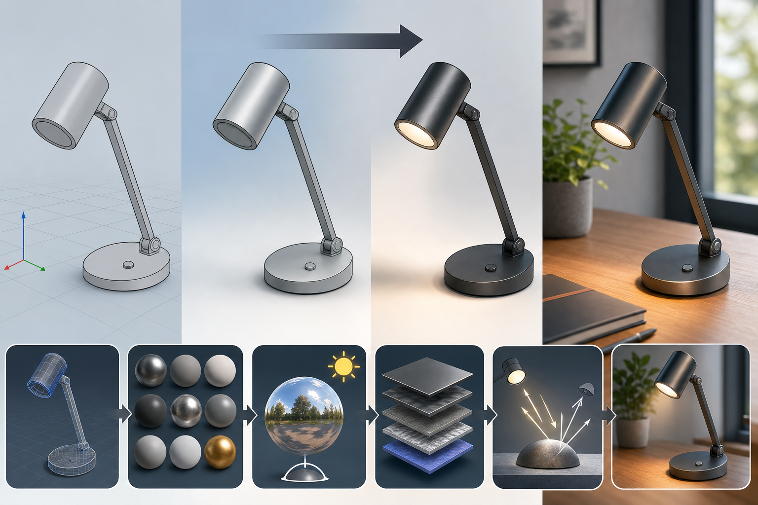


From Accurate Geometry to Believable Appearance
The original CAD priority was definition, not illusion
For most of its early history, design software was built to answer engineering questions before it answered visual ones. A CAD system had to define points, curves, surfaces, dimensions, constraints, topology, tolerances, assemblies, drawings, bills of materials, and manufacturable intent. Systems such as DAC-1 at General Motors, CATIA at Dassault, CADAM from Lockheed, Computervision CADDS, Intergraph, and later AutoCAD, Pro/ENGINEER, Unigraphics, SolidWorks, and Inventor were judged primarily by whether they could describe a product precisely enough to design, analyze, document, and manufacture it. The screen image was a working representation of the model, not a prediction of how the object would behave under light. Wireframes, hidden-line drawings, flat colors, simple specular highlights, and shaded viewports helped engineers understand form, but they rarely represented real optical behavior. A glossy plastic part might be given a blue color and a bright highlight, yet the software was not modeling how the polymer’s surface roughness, Fresnel response, pigment absorption, or coating layer bent and scattered light. Early CAD visualization was therefore a communication aid, while physically based rendering later became a design instrument.
- Early CAD images emphasized geometric clarity, drafting accuracy, and assembly comprehension.
- Materials were usually assigned as display colors rather than as optical models.
- Lighting existed mainly to make the viewport readable, not to simulate measured illumination.
The Long Gap Between CAD Shading and Real Product Images
Viewport realism arrived in layers, not all at once
The earliest interactive graphics breakthroughs made digital design possible long before realistic appearance became practical. Ivan Sutherland’s Sketchpad, developed at MIT in 1963, established the idea that designers could interact directly with graphical geometry on a screen, using constraints and a light pen to manipulate drawings in ways that anticipated much of later CAD. Yet Sketchpad was not a product rendering system; its importance was interactivity, not photorealism. During the 1970s and 1980s, raster displays, frame buffers, z-buffering, scan conversion, and shaded polygon pipelines gradually transformed engineering graphics from line drawings into filled, depth-sorted, colored models. Researchers such as Edwin Catmull, Jim Blinn, Bui Tuong Phong, Henri Gouraud, and Martin Newell gave the field essential algorithms for texture mapping, shading, reflection models, and object representation. In CAD, these methods made models easier to inspect, rotate, and explain, but the resulting views were still approximations. A shaded model could reveal curvature, silhouette, and interference, yet it did not reliably tell a designer whether a satin aluminum knob would look premium, whether a black plastic seam would disappear, or whether a transparent lid would reveal internal components attractively.
Why Early Visualization Was Not Truly Physics-Based
Painted surfaces were not the same as simulated materials
The weakness of early product visualization was not that images were useless; it was that they were often visually persuasive without being physically meaningful. A user could apply red, chrome, glass, or rubber appearances, but those labels typically controlled a small set of artist-friendly parameters such as diffuse color, shininess, reflection intensity, opacity, and perhaps a texture map. Real materials are more complex. Brushed stainless steel is anisotropic, car paint may have pigments, flakes, clear coats, and depth-dependent reflections, molded plastic may show micro-scratches and subsurface diffusion, and frosted glass transmits light differently depending on thickness and surface roughness. Early viewport lights frequently consisted of one or two directional or point lights placed for convenience, not actual luminaires with intensities, sizes, color temperatures, measured distributions, or environmental context. This meant that design teams could create attractive renderings, but they could not always trust them for repeatable comparison. The central historical movement in visualization was therefore a shift from “make the geometry understandable” toward predict how the product might look in the real world, with the crucial word being “predict.”
- Traditional shading often used simplified diffuse and specular terms rather than complete light transport.
- Reflection and refraction were frequently faked or limited to special rendering modes.
- Material libraries became valuable only when their parameters corresponded to repeatable optical behavior.
The Rendering Research That Changed Design Visualization
Ray tracing, global illumination, and the move toward light transport
Modern product rendering owes much to computer graphics research that initially developed outside ordinary engineering CAD. Turner Whitted’s 1980 paper on recursive ray tracing demonstrated a practical way to calculate reflections, refractions, and shadows by tracing rays through a scene, establishing an intellectual foundation for realistic glass, mirrors, polished metals, and transparent components. At Cornell University, Donald Greenberg and colleagues advanced radiosity and global illumination research, and the famous Cornell Box became an enduring test scene because it exposed whether a renderer could reproduce indirect light, color bleeding, and spatial illumination in a controlled environment. These ideas mattered because products are not seen under isolated highlight tricks; they are seen in rooms, showrooms, kitchens, cars, stores, factories, and hands, with light bouncing from surrounding surfaces. In engineering terms, the renderer became less like a painter and more like a simulator. The goal was no longer only to draw an object but to account for the transfer of energy from light sources to surfaces to camera, including the many indirect paths that create softness, depth, and visual credibility.
The Technical Language of Physically Based Rendering
BRDFs, Fresnel behavior, roughness, and energy conservation
Physics-based rendering brought a more disciplined vocabulary into product design software. One core concept is energy conservation: a surface should not reflect more light than it receives, which sounds obvious but was often violated by older artistic shading models. Another is the bidirectional reflectance distribution function, or BRDF, which describes how light arriving from one direction is reflected in another direction. Microfacet models, associated with research by people such as Robert Cook, Kenneth Torrance, and later many graphics researchers refining practical implementations, model a surface as countless tiny facets whose orientation distribution determines glossiness, roughness, and highlight shape. Fresnel effects explain why reflections become stronger at grazing angles, which is essential for believable plastics, glass, clear coats, and water-like surfaces. Metallic response distinguishes conductors from dielectrics: metals color reflections through their optical properties, while plastics and ceramics usually have colored diffuse bodies with largely neutral surface reflections. Subsurface scattering and spectral behavior add still more realism for wax, translucent polymers, skin-like materials, milky glass, food packaging, silicone, and resin. These concepts became crucial because industrial designers make decisions at the boundary between shape and perception.
- Roughness controls how broad or sharp highlights appear across a surface.
- Metallic response changes whether color comes from reflected light or from the body of the material.
- Fresnel effects make edges and grazing angles reflect differently from front-facing surfaces.
- Surface scattering helps translucent plastics, rubber, resin, and silicone avoid a flat computer-generated look.
How Film Rendering Influenced Industrial Design
RenderMan, photon mapping, and production-quality materials
The film industry pushed rendering toward extreme visual sophistication, and product design software eventually absorbed many of its lessons. Pixar’s RenderMan, shaped by figures such as Ed Catmull, Pat Hanrahan, Rob Cook, Loren Carpenter, and others at Pixar, popularized programmable shading and production rendering practices that allowed artists to define complex surface behavior. Although film rendering was often judged by storytelling and cinematic control rather than engineering repeatability, its breakthroughs made designers expect richer material behavior, better lighting, and more convincing images. Henrik Wann Jensen’s work on photon mapping and subsurface scattering gave computer graphics powerful tools for simulating indirect illumination and translucent materials. These techniques directly influenced how designers represented frosted plastics, medical devices, cosmetics packaging, fabric, ceramics, and rubber-like consumer products. Automotive visualization also benefited from film-grade thinking because car paint is optically layered: primer, colored base coat, metallic flakes, pearl effects, clear coat, orange peel, and environment reflections all shape perception. The bridge from film to design was not a simple transfer of pretty images; it was a migration of mathematical light transport, shader structure, sampling strategies, and material description into product workflows where appearance affects cost, brand identity, manufacturability, and customer acceptance.
Why Realism Had to Become Useful, Not Merely Beautiful
Design decisions require repeatability and control
A photorealistic image can impress executives, but product development needs something more demanding: controlled realism that supports comparison. A designer evaluating two black finishes on a consumer electronics enclosure must understand whether the first finish hides fingerprints better, whether the second exaggerates parting lines, and whether either one makes curvature breaks look cheap under retail lighting. A packaging team examining translucent bottles must know whether material thickness, liquid color, cap finish, and label opacity work together. A furniture designer judging fabric texture needs reliable scale, weave direction, and sheen. Automotive designers studying interior trim require accurate response from leather grain, brushed aluminum, piano black plastic, stitching, rubber seals, and touch-screen glass. This is why visual realism and engineering usefulness are not identical. A beautiful image may be heavily art-directed, while a useful rendering must be repeatable, parameterized, and tied to understandable inputs. Product visualization became part of design when teams could use it to compare alternatives before tooling, detect appearance risks before samples, and communicate decisions across engineering, marketing, manufacturing, and executive review without pretending that every attractive render was a measured optical truth.
- Automotive teams needed trustworthy previews of paint, glass, wheels, trim, upholstery, and interior lighting.
- Consumer electronics teams needed to judge seams, edge reflections, fingerprints, screens, coatings, and premium finishes.
- Packaging teams needed to evaluate transparency, label reflectivity, liquid color, plastic thickness, and shelf lighting.
- Furniture and soft-goods teams needed better previews of fabric, grain, stitching, scale, and surface wear.
How Rendering Moved Into Commercial Product Design Tools
From specialist visualization packages to everyday CAD workflows
For many years, realistic rendering lived outside mainstream CAD. Engineers and industrial designers frequently exported NURBS surfaces, polygon meshes, IGES files, STEP data, or proprietary geometry into specialist visualization software. Alias and Wavefront were especially important in high-end industrial design, automotive surfacing, and animation before their tools became part of Autodesk’s broader portfolio. 3D Studio, later 3ds Max, became widely used for visualization on PCs; Softimage became influential in animation and advanced digital content; Maya emerged from the Alias and Wavefront lineage as a powerful modeling, animation, and rendering environment; Cinema 4D from Maxon gained popularity for accessible motion graphics and product visualization. This separation reflected the division between engineering geometry and image production. CAD systems were strong at parametric part definition, assemblies, drawings, constraints, and manufacturing data, while visualization packages were stronger at cameras, lights, materials, textures, environments, and final image control. The workflow was powerful but fragile: imported models needed cleanup, tessellation choices mattered, material assignments could break, changes required re-exporting, and designers often depended on rendering specialists. The eventual goal was clear: bring high-quality rendering directly into the design loop rather than treating it as a disconnected downstream activity.
Major CAD Vendors and the Integration of Visualization
Autodesk, Dassault Systèmes, Siemens, PTC, and Luxion
Commercial design software vendors responded by embedding rendering and visualization more deeply into product development environments. Autodesk connected visualization across AutoCAD, Inventor, Fusion 360, 3ds Max, and related cloud and rendering technologies, reflecting its unusual position across drafting, mechanical design, media, and visualization. Dassault Systèmes expanded from CATIA’s high-end engineering heritage and SOLIDWORKS’ mid-market mechanical design strength into broader product-experience visualization through tools and acquisitions associated with 3DEXCITE and related platforms. Siemens supported visualization through NX, Teamcenter Visualization, JT-based workflows, and high-end manufacturing and engineering review environments, where large assemblies and product lifecycle context are as important as surface beauty. PTC incorporated rendering into Creo so mechanical and industrial design teams could evaluate appearances without leaving parametric design workflows. Luxion’s KeyShot deserves special attention because it became influential by reducing the expertise barrier: drag-and-drop materials, HDR environments, fast previews, and approachable controls made high-quality product renderings available to industrial designers and engineers who did not want to build complex shader networks. KeyShot’s historical significance is not merely image quality; it helped normalize the idea that rendering should be immediate, iterative, and understandable inside product design practice.
- Autodesk linked CAD, visualization, and digital content creation across several product families.
- Dassault Systèmes connected engineering design with product experience and brand visualization.
- Siemens emphasized visualization for large assemblies, lifecycle review, and manufacturing context.
- PTC brought rendering into mechanical and parametric product design workflows.
- Luxion KeyShot made professional product rendering more approachable for non-specialist users.
GPU Acceleration Changed Expectations for Interactivity
NVIDIA, AMD, Iray, OptiX, RTX, and the shrinking wait time
The history of PBR in product design cannot be separated from the graphics hardware revolution. Early photorealistic rendering was slow because ray tracing, global illumination, soft shadows, glossy reflections, refractions, and sampling-heavy effects demanded enormous computation. Designers could wait hours for a final image, but they could not evaluate dozens of finish variations interactively if every decision required an overnight render. GPU acceleration changed that expectation. NVIDIA’s CUDA ecosystem, OptiX ray tracing framework, Iray renderer, and later RTX hardware with dedicated ray tracing acceleration helped move physically based and ray-traced rendering closer to real-time design review. AMD also advanced professional graphics capabilities through Radeon Pro hardware, ProRender, and open rendering initiatives. As GPUs became programmable and massively parallel, the boundary between viewport and final render began to collapse. Designers could rotate a model, change an HDR lighting environment, adjust roughness, swap a brushed metal for anodized aluminum, alter clear-coat strength, and see increasingly reliable feedback within seconds. This changed behavior: rendering was no longer only a final presentation stage but became part of exploration. The most important effect of GPU acceleration was psychological as much as technical, because teams began to expect interactive visual truth while designing.
Material Libraries Made PBR Practical for Designers
CMF workflows required reusable, intelligible appearance definitions
Physics-based rendering could not become mainstream if every designer had to become an optical physicist. Its adoption depended on material libraries, presets, measured data, and interfaces that translated complex models into manageable controls. In color, material, and finish work, usually called CMF, designers need to compare plastics, paints, anodized metals, glass, elastomers, fabrics, wood veneers, ceramics, coatings, and printed graphics. Practical PBR materials therefore include properties such as base color, roughness, metallic value, specular level, index of refraction, transmission, opacity, bump, normal maps, displacement, anisotropy, clear coat, sheen, and sometimes measured reflectance curves or scanned texture data. Companies such as X-Rite Pantone, AxF technology developers, Adobe with Substance materials, Chaos with V-Ray materials, Luxion with KeyShot libraries, Autodesk with appearance assets, and Dassault, Siemens, and PTC through their own ecosystems helped establish reusable material definitions. The material library became a design language. A team could assign alternatives, preserve them across revisions, render them under consistent environments, and discuss whether a product should feel rugged, clinical, premium, playful, sustainable, or discreet. In that sense, CMF iteration became computational: designers could explore perception through adjustable, repeatable parameters rather than relying only on physical samples and subjective memory.
- Reusable PBR materials reduced the need to build shaders from scratch.
- Roughness and normal maps helped represent molded texture, stitching, grain, scratches, and brushed finishes.
- Measured or standardized material data improved consistency across teams and rendering systems.
- CMF workflows benefited because appearance alternatives could be reviewed before physical sampling.
Rendering Became Part of the Product Development Process
Appearance decisions moved earlier in the timeline
Physics-based rendering entered product design because visual decisions became inseparable from design decisions. The appearance of a product is not decoration applied after engineering; it affects perceived quality, usability, ergonomics, manufacturability, brand recognition, assembly strategy, cost, and customer trust. A small change in edge radius can transform how highlights travel across a device. A different texture can hide sink marks or make a part look cheap. A glass component may require thickness adjustments to avoid unappealing refraction. A metallic coating may reveal waves in a surface that were invisible in a shaded CAD viewport. By evaluating these issues digitally, teams can make decisions before prototype tooling, before physical samples, before expensive photography, and before marketing campaigns lock in expectations. This does not eliminate prototypes, because touch, weight, durability, and manufacturing variation still require physical validation. It does, however, reduce blind iteration. The historical importance of PBR is that it made appearance a first-class design parameter in the same environment as geometry. A product team could discuss curvature, seam placement, material finish, lighting response, and marketing imagery from the same digital model, increasing alignment between industrial design, engineering, manufacturing, and brand stakeholders.
The Historical Merger Behind Modern Product Visualization
CAD, graphics research, materials, GPUs, and product experience converged
The rise of physics-based rendering in design software represents a merger of worlds that were once separate. CAD contributed exact geometry, feature history, assemblies, drawings, tolerances, and product structure. Computer graphics research contributed ray tracing, global illumination, BRDFs, sampling theory, shading languages, texture mapping, and camera simulation. Material science contributed knowledge about reflectance, roughness, coatings, translucency, pigments, metals, polymers, fabrics, and measured appearance. GPU computing contributed speed, interactivity, and the possibility of design-time visual feedback. Industrial design contributed CMF strategy, form language, brand expression, and human-centered judgment. Marketing visualization contributed the demand for compelling product imagery before manufactured products existed. Product lifecycle systems contributed configuration, collaboration, and review context. When these domains converged, rendering changed status. It stopped being a decorative export and became part of concept exploration, design validation, stakeholder review, sales configuration, and digital product experience. The next phase will blur the boundary further through real-time ray tracing, AI-assisted material creation, cloud rendering, augmented reality, virtual reality, and digital twins. In the long history of design software, PBR matters because it turned appearance into something designers could compute, compare, and refine, not merely something artists could paint at the end.
Also in Design News






