Your Cart is Empty
Mesh-to-CAD Acceleration Stack: 5 Capabilities for Faster Reverse-Engineering Reconstruction
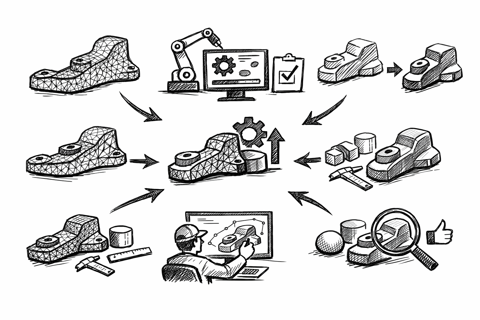


Faster part reconstruction in reverse engineering means moving from scanned or meshed reality to an editable CAD model with fewer iterations, fewer surface patches, and far less manual rework. Practically, the fastest teams treat reconstruction as a workflow stack rather than a collection of tools: prepare the mesh, extract intent-critical features, build robust references, surface with continuity targets, then validate and iterate using deviation insight. When these five functionalities work together, you spend less time “chasing the scan” and more time producing CAD that edits predictably and meets functional tolerances.
Mesh Preparation & Segmentation Tools (clean inputs = exponential time savings)
What to master
Mesh preparation is where reconstruction speed is either earned or lost. The goal is not to create a “pretty mesh,” but to create one that supports stable fitting and surfacing.
Noise reduction / smoothing strategies that preserve edges and feature fidelity require selective thinking. Global smoothing can erase exactly the information you need (creases, parting lines, sharp breaks). Prefer workflows that allow:
- Feature-preserving smoothing (edge-aware filters) where curvature is continuous
- Local smoothing brushes that avoid transitions, corners, and small fillets
- Separate treatment of machined faces versus cast or organically worn zones
Hole filling approaches should be chosen based on downstream surfacing intent. Some holes must be filled to make sections and surface tools behave; others are better ignored to avoid injecting fake geometry that you will later “correct” back out.
- Patch/fill when the missing region lies on a surface you will reference for a fit or section curve
- Ignore when the hole is a non-functional void, occluded scan region, or irrelevant underside
- Use minimal, low-curvature fills for continuity, not “invented” detail
Mesh decimation settings should reduce triangle count while protecting curvature-critical zones. Decimation is not just about performance; it’s about preventing downstream ripples when curves and surfaces are derived from uneven tessellation density. The most reliable setups:
- Preserve boundaries and sharp edges (do not allow edge collapse across creases)
- Use curvature-weighted decimation (retain triangles where curvature changes)
- Maintain higher density around fillets, ribs, embossed detail, and transitions
Region/feature segmentation is where reverse engineering starts looking like CAD again. The objective is to separate the mesh into logical surface families such as planes, cylinders, blends, and freeform zones so that each can be fit and surfaced using the most appropriate method.
Why it matters in reconstruction speed
A mesh with noise, holes, inconsistent density, and unsegmented regions causes error propagation: a bad mesh leads to unstable fits; unstable fits produce poor references; poor references force surface rework. That rework is rarely linear: a single incorrect cylinder axis can force multiple downstream patches and trims to be rebuilt.
Clean and segmented input enables a “fit once” strategy. You fit primitives and derive curves a single time with confidence, instead of repeatedly refitting because the selection region was contaminated by noise, edge rounding, or unrelated geometry.
Practical checklist
- Identify datum-worthy zones first: mounting faces, bores, sealing surfaces, alignment bosses, and any mating interface.
- Clean and simplify globally (remove obvious outliers, unify normals if needed), then refine locally around edges and transition zones.
- Segment the mesh into logical surface families before extracting geometry: planar regions, cylindrical features, blend bands, and freeform skins.
Common pitfalls to avoid
Over-smoothing is the fastest way to destroy design intent. It rounds edges, broadens fillets, and shifts crease locations so that the reconstructed CAD will look “soft” and measure wrong where it matters.
Over-decimation breaks curvature continuity and produces “faceted curvature,” which then shows up as wavy section curves or rippled NURBS surfaces. If a surface needs to be Class-A smooth or dimensionally stable, don’t starve its source region of triangles.
Feature Extraction: Best-Fit Primitives & Analytical Recognition (planes, cylinders, cones, spheres)
What to master
Once the mesh is prepared, the biggest acceleration comes from turning triangle regions into analytic CAD features. Best-fit primitives are more than convenience features; they are the anchors that define the part’s functional coordinate system.
Best-fit plane/cylinder/cone creation should be performed on carefully controlled selection sets. Many tools allow region growing, paint selection, or angle-based capture; use these to avoid including adjacent blends or worn edges, which can bias the fit.
Robust axis extraction is essential for holes, bores, shafts, bosses, and rotational symmetry. A cylinder with a slightly incorrect axis won’t just measure wrong; it will corrupt patterns, coaxial stacks, and mates in downstream assemblies.
Batch recognition patterns can be a major multiplier if you have repeated features such as hole arrays, fin patterns, or stepped coaxial bores. Recognition routines that identify consistent radii, shared axes, or common normals help you build structured CAD quickly rather than re-fitting each entity as an isolated artifact.
Outlier control is the quiet skill behind stable fitting. Wear, dents, scan noise, and partial occlusion create outliers that can pull a fit away from the “true” intent. Master selection trimming and re-fitting workflows so you can converge quickly.
Where it accelerates reconstruction
Analytic recognition converts “triangle soup” into editable CAD anchors immediately. Each recognized plane or cylinder reduces the need for freeform patching and provides a stable reference for sketch planes, revolve/extrude features, and assembly datums.
Capturing analytic intent early also reduces the number of surfaces needed. A clean cylinder replaces multiple freeform patches that would otherwise be required to approximate a rotational feature.
Tactics reverse engineers rely on
- Fit primitives on functional surfaces first: interfaces, mounting pads, sealing faces, bearing bores, and alignment features.
- Use multiple localized fits rather than one global fit when wear or deformation exists (for example, fit each bearing seat independently, then manage coaxial intent through references rather than forcing a single compromised fit).
- Preserve coaxiality and parallelism intent by referencing shared axes and planes across multiple primitives instead of letting each fit float independently.
Quality controls
Do not commit a primitive simply because the software produced it. Track deviation statistics such as max and mean error on each fitted entity. A cylinder fit might have an acceptable mean deviation but an unacceptable max deviation concentrated in a functional region, which is a red flag that your selection set includes a blend, a nick, or scan artifact.
Also verify that fit tolerances align with manufacturing realities. A cast exterior may legitimately deviate more, while a machined sealing land or precision bore typically demands tighter acceptance. Treating every region equally is a common driver of wasted effort.
Curve & Edge Derivation for Design-Intent Skeletons (sections, silhouettes, boundary curves)
What to master
If primitives provide the anchors, curves provide the skeleton. A strong curve network is what makes freeform surfacing predictable rather than improvised.
Section curve generation using planar cuts is the most controllable way to capture profiles and transitions. Strategic sectioning exposes the true intent of ribs, bosses, draft angles, and blend behavior in a way that raw mesh shading cannot.
Silhouette/outline extraction matters when the exterior boundary is complex or when the part’s functional envelope must be respected. Silhouettes can provide stable outer constraints even when local mesh detail is noisy.
Edge detection on meshes (crease/feature lines) is fundamental for locating sharp transitions: flange breaks, parting lines, stamped edges, and abrupt curvature changes. These edges often define where you should split surfaces later.
Curve fitting options—degree, tolerance, and point distribution—determine whether your curves are editable and stable. A curve that perfectly follows a noisy mesh may “fit,” but it will generate surfaces that are impossible to keep smooth and will be extremely sensitive to small edits.
Why it’s a speed multiplier
A clean curve skeleton eliminates time-consuming surface guessing. Instead of pushing control points until the deviation map looks acceptable, you build surfaces from well-placed boundaries and sections that already encode the part’s design logic.
It also simplifies downstream surfacing: fewer spans, cleaner continuity, and easier edits. In practice, an hour spent simplifying and re-parameterizing curves can save many hours of patch repair and continuity tuning later.
Implementation details that make the difference
Section spacing strategy should be adaptive. Dense sections belong where curvature changes rapidly (tight blends, changing draft, transitional “shoulders”). Sparse sections belong on simple runs (long planar or near-cylindrical zones). This avoids building surfaces that are over-constrained by redundant, noisy data.
Curve simplification and re-parameterization are often the difference between a surface that highlights well and one that “grabs” light with ripples. Simplify by reducing control points where possible while staying within a tolerance that matches the region’s functional needs.
Enforcing symmetry is another major speed lever. When a part is intended to be symmetric but the scan is not (because of noise, wear, or partial occlusion), extract and rebuild half, then mirror. This produces CAD that behaves like design intent rather than like measured imperfection.
Pitfalls
Over-fitting noisy mesh data creates wavy curves, which in turn create unstable surfaces that require excessive continuity management. If your curves look “nervous,” the resulting surfaces will be worse.
Under-fitting critical profiles causes systematic deviation that only becomes obvious late, after surfaces and trims are built. This leads to expensive rework because early skeleton decisions propagate forward.
Guided Freeform Surfacing with Continuity Control (G0/G1/G2)
What to master
Guided surfacing converts the curve skeleton and primitives into a coherent CAD skin. The central skill is disciplined surface planning: where to split, what continuity to demand, and which references to trust.
Patch layout planning is a design activity, not a software operation. Choose splits where the physical part naturally changes behavior: along feature lines, at parting lines, at sharp creases, or where manufacturing transitions (machined to cast) are expected. Avoid arbitrary splits that create tiny patches with fragile boundaries.
Surface creation tools should follow extracted curves while adhering to mesh constraints. Depending on the software, this may involve network surfaces, boundary surfaces, lofts with multiple sections, sweep-like tools, or explicit mesh-constrained surfacing where the solver pulls the surface toward the mesh within a tolerance envelope.
Continuity tuning between adjacent surfaces is where reconstruction quality becomes predictable. G0 (position) is often sufficient for sharp edges and hard breaks. G1 (tangent) is typical for most functional blends. G2 (curvature) is crucial where flow and highlight quality matter or where a surface must transition smoothly over a broad area.
Blend and transition surfacing must respect manufacturing realities: fillets that are not arbitrary but sized and located as they would be produced, draft considerations where molding is implied, and parting lines that align with segmentation and crease detection rather than being “drawn in” after the fact.
How it speeds reconstruction
Guided surfacing accelerates work by minimizing manual “surface chasing.” When surfaces are built from a stable skeleton and constrained sensibly to the mesh, you have fewer degrees of freedom to fight, and edits have predictable impact.
It also produces CAD that edits predictably. That matters because reconstruction rarely ends at “match the scan.” It often continues into tolerance adjustments, feature suppression, simplification for manufacturing, or modifications for a mating assembly.
Workflow
- Build primary structural surfaces first: datums, major analytic areas (planes, cylinders, cones), and any surfaces that define the coordinate logic of the part.
- Add secondary freeform skins guided by section curves and boundary curves, keeping spans and curve complexity under control.
- Apply continuity targets at joins early, then lock in trims and edges late to avoid re-trimming every time a surface updates.
Quality and robustness guidance
Favor fewer, better patches over many small ones, unless the physical feature layout demands segmentation. Excessive patching increases the number of joins you must manage and multiplies the opportunities for continuity failure.
Use curvature continuity strategically. Apply G2 continuity where aesthetics and surface flow matter (visible exterior skins, ergonomic forms, optical continuity). Use G1 where function dominates (many internal transitions, non-visible but sealed surfaces, generalized blends). Applying G2 everywhere can actually slow reconstruction because it can over-constrain the system and force repeated adjustments for marginal benefit.
Deviation Analysis & Iterative Correction (close the loop without starting over)
What to master
Deviation analysis is the feedback system that turns reconstruction into a controlled process. Without it, you either accept unknown risk or you overbuild surfaces “just in case,” which is slow and often counterproductive.
3D deviation maps compare mesh to reconstructed surfaces or solids with a color scale that exposes where the model is inside or outside the scan. The key is to use deviation tools continuously, not only at the end.
Localized deviation inspection is crucial for functional zones: seals, contact interfaces, bores, bearing seats, and mounting faces. Global heatmaps can hide local failures if the scale is set for the entire part.
Targeted refit workflows are what enable iteration without restarting. Depending on what the deviation reveals, you may:
- Adjust a controlling curve (move a section, simplify a spline, tighten a boundary)
- Refit a primitive using a cleaner or more appropriate selection set
- Reflow a single surface patch while preserving neighboring continuity constraints
Tolerance-driven acceptance criteria keeps iteration rational. Different surfaces justify different thresholds: functional accuracy for mating geometry, and looser thresholds for cosmetic or cast-like regions that are inherently variable.
Why it’s essential for faster outcomes
Deviation analysis prevents late-stage surprises by validating continuously rather than discovering mismatches after the model is fully trimmed, stitched, and feature-built. Early discovery means corrections are local and cheap.
It also enables controlled iteration: fix only what changes functional accuracy. If you try to eliminate every last red pixel on a deviation map, you are often optimizing against scan artifacts, not design intent.
Validation approach
- Validate datums and primary features first: axes, planes, mating faces, and any references that other geometry depends on.
- Validate transitions next: blends, edge breaks, and fillets, because these influence how patches join and how solids will stitch.
- Validate freeform skins last using region-based thresholds so you don’t over-correct non-critical areas.
Common mistakes
Chasing max deviation outliers is a classic trap. Outliers are frequently driven by scan artifacts, occluded regions, or reflective surfaces. If the mean and functional zones are acceptable, an isolated extreme value may not justify geometric change.
Using a single tolerance for everything leads to unnecessary rework. It forces high-precision treatment on low-importance surfaces and masks the need for tighter control where function demands it. The result is slower reconstruction and sometimes worse functional outcomes because effort was spent in the wrong locations.
Conclusion
The mastery stack for faster reconstruction is consistent: clean and segment the mesh, recognize analytic geometry, build a curve skeleton that reflects design intent, surface with controlled continuity, then validate with deviation-driven iteration. The practical takeaway is that reconstruction speed comes from reducing rework loops. Each of these five Mesh2Surface capabilities shortens a specific loop—turning reverse engineering from an artisanal, trial-and-error exercise into a predictable, repeatable process that produces robust, editable CAD.
Also in Design News