Your Cart is Empty


Machine Learning Feature Recognition in Advanced CAD Workflows


Why Feature Recognition Still Matters in Advanced CAD Workflows
Turning Static Geometry into Engineering Meaning
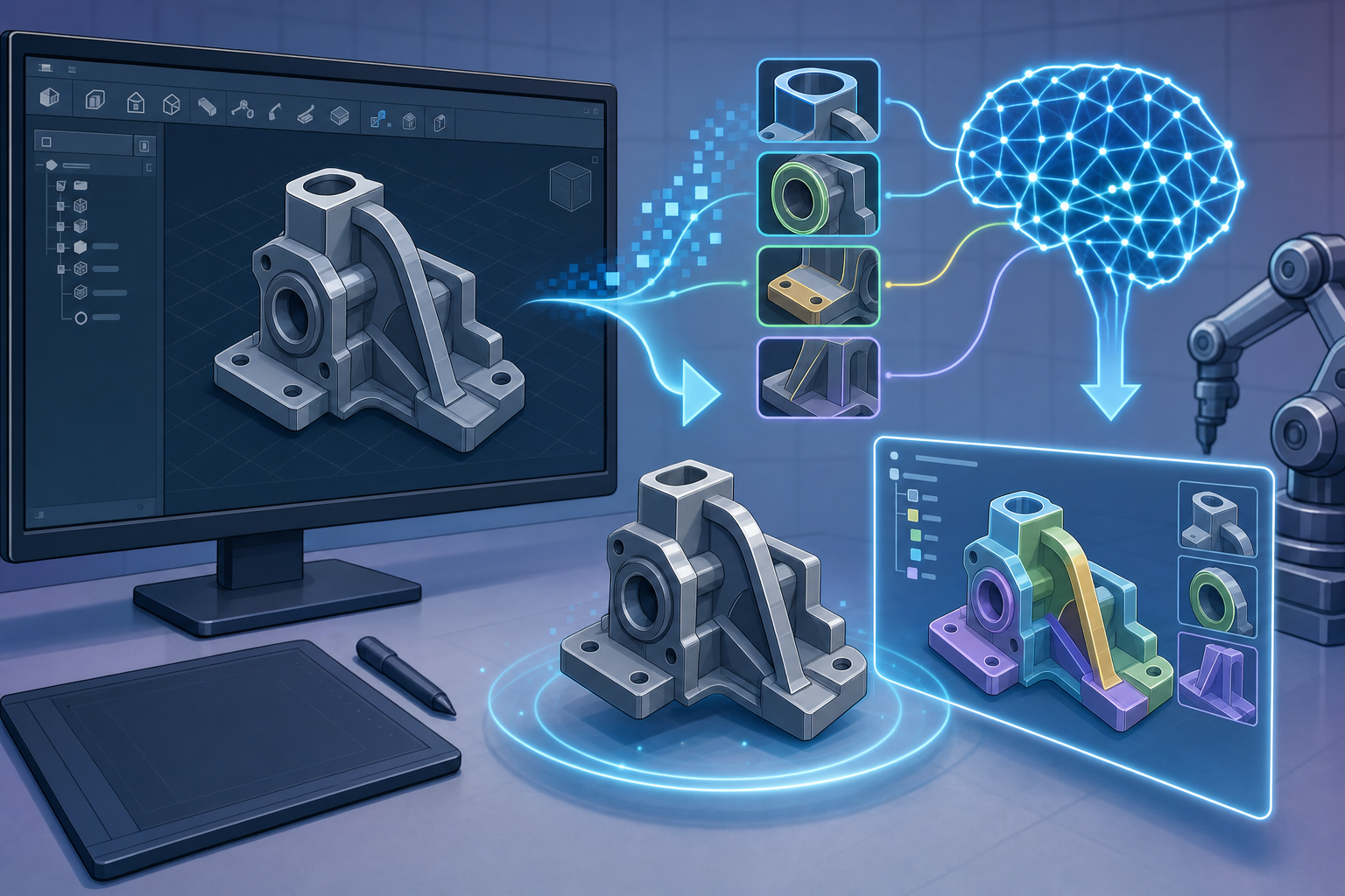
Feature recognition in CAD is the process of identifying meaningful design and manufacturing elements inside solid geometry, such as holes, fillets, pockets, bosses, ribs, chamfers, slots, patterns, bends, turned profiles, and other recurring geometric conditions that engineers and manufacturers understand as functional entities. In a native parametric model, these elements may already exist as part of a feature tree, but in many real engineering workflows the receiving system sees only boundary representation data: faces, edges, vertices, tolerances, and topology. Feature recognition translates “dumb” imported geometry into editable, semantic, process-aware models, allowing software to infer that a set of cylindrical faces is not just geometry but possibly a drilled hole, that a constant-radius transition is a fillet inserted for stress reduction or manufacturability, or that several repeated cuts define a fastening pattern. This distinction matters because modern CAD workflows are no longer isolated modeling exercises. Geometry must move into CAM, CAE, inspection, additive manufacturing preparation, cost estimation, product visualization, and lifecycle systems. Without recognized features, every downstream process must rediscover meaning from raw shape, usually through manual interpretation or brittle rules.
The Persistent Problem of Imported and Legacy CAD Data
Traditional CAD data exchange has always struggled with design intent. A STEP, IGES, SAT, or Parasolid file may preserve an accurate solid body, but it commonly loses the parametric timeline, sketches, constraints, named features, equations, configurations, and modeling rationale that shaped the original part. Legacy models often contain geometry but very little information about why that geometry exists, which operations created it, or how it should change when the design is revised. This creates a significant burden for engineers who must modify supplier parts, repair archived designs, standardize component libraries, or prepare imported models for manufacturing. Manual reconstruction is slow because the user must inspect geometry, determine likely operations, recreate sketches, rebuild features, and validate that the reconstructed model behaves like the original. It is also error-prone because many features are ambiguous: a cylindrical cavity may be drilled, bored, cast, printed, or inserted as a clearance condition. In advanced environments, this ambiguity becomes expensive because an incorrectly reconstructed feature can propagate into tooling decisions, simulation assumptions, tolerance planning, and manufacturing cost estimates.
Why Automation Has Become More Urgent
The urgency behind automated feature recognition has increased because engineering organizations now reuse more external and historical data than ever before. Supplier models arrive continuously, design libraries contain decades of parts created in different systems, and product teams are expected to evaluate manufacturability, sustainability, cost, simulation readiness, and procurement risk earlier in the design cycle. This requires models to be understandable by software, not merely visible to humans. If a quoting system can automatically identify milled pockets, drilled holes, tight internal radii, and inaccessible surfaces, it can estimate manufacturing effort far faster than a manual reviewer. If CAM software can recognize machinable features, it can propose operations and toolpaths with less programming time. If simulation tools can identify small fillets, cosmetic holes, contact areas, and load-bearing regions, they can automate model simplification and mesh preparation. In this context, machine learning moves feature recognition from rule-based geometry interpretation toward probabilistic, context-aware understanding. Instead of relying only on fixed geometric rules, ML-based systems learn from examples and can evaluate partial, noisy, or ambiguous situations in ways that more closely resemble expert engineering judgment.
- Imported models often retain shape but lose editable feature history.
- Legacy components may need modification, classification, quotation, or simulation without original design intent.
- Automated recognition improves digital thread continuity between CAD, CAM, CAE, PLM, inspection, and manufacturing planning.
- Machine learning helps software infer likely meaning when pure geometry rules are incomplete or ambiguous.
How Machine Learning Recognizes CAD Features
From Deterministic Rules to Learned Geometric Context
Traditional feature recognition methods rely heavily on geometric rules, topology graphs, face adjacency, surface types, concavity, convexity, loop structures, and Boolean decomposition. These methods are powerful when features are clean, isolated, and similar to their expected definitions. For example, a through-hole can be detected by finding cylindrical faces bounded by two planar openings, while a pocket can be identified by a set of connected faces forming a concave depression. However, production parts rarely remain so tidy. Features overlap, fillets blend boundaries, patterns are interrupted, imported tolerances distort surfaces, and design features interact with manufacturing features in ways that violate simple assumptions. Machine learning changes the recognition task by allowing systems to learn statistical patterns from annotated CAD datasets. Instead of asking only whether geometry matches an exact rule, a trained model can estimate the probability that a region represents a pocket, boss, rib, bend, undercut, or fastener interface based on topology, shape, proportion, neighborhood context, and recurrence. This does not eliminate geometric reasoning; it expands it. The most practical systems combine exact CAD kernel data with AI classifiers so that recognition is both mathematically precise and contextually flexible.
Graph Neural Networks for Boundary Representation Data
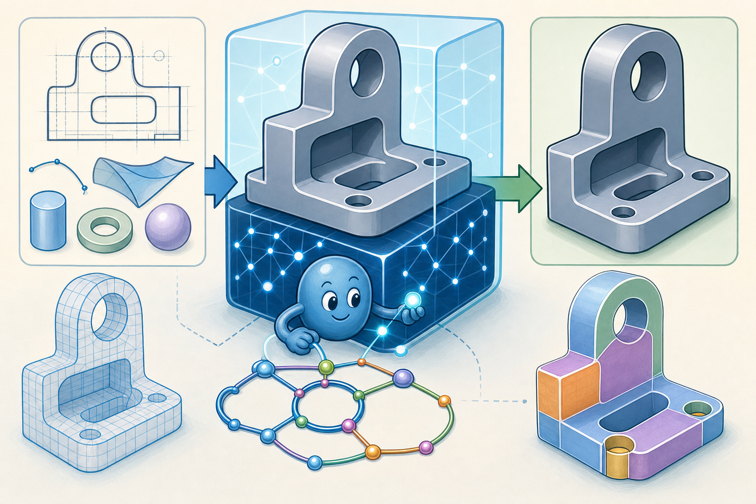
One of the most promising approaches is the use of graph neural networks, often applied to boundary representation models. A CAD solid can be interpreted as a graph in which faces are nodes, edges represent adjacency, and attributes describe surface type, curvature, area, orientation, loop count, convexity, and other geometric relationships. This is attractive because B-rep topology is already the native language of many CAD kernels. A graph model can learn that certain arrangements of cylindrical, planar, and conical faces tend to represent holes, countersinks, counterbores, slots, or machined pockets. It can also understand that feature meaning depends on neighborhood context. A cylinder surrounded by planar faces may behave differently if it is one member of a repeated bolt pattern, intersects a rib, terminates inside a blind cavity, or crosses a curved housing wall. Graph methods are particularly useful for recognizing features whose identity depends on connectivity rather than raw volume. They can preserve engineering precision better than voxel methods because they operate on faces and relationships directly, making them well suited to production-grade CAD applications where exact surface definitions remain important.
Volumetric, Point Cloud, Mesh, and Hybrid Models
Other machine learning approaches analyze CAD models as voxel grids, meshes, point clouds, or hybrid geometric structures. 3D convolutional neural networks can process volumetric representations in a way that resembles image recognition extended into three dimensions. This is useful for spatial pattern recognition, especially when the system needs to understand gross shape, internal cavities, or repeated local structures. The drawback is that voxelization can sacrifice precision, particularly for small radii, thin walls, tight clearances, and detailed machining features where engineering accuracy matters. Point cloud and mesh-based models are valuable for reverse engineering, scan-to-CAD workflows, additive manufacturing inspection, and polygonal design environments, where exact parametric surfaces may not exist. These models can identify ribs, bosses, holes, freeform transitions, and deformations from sampled geometry, but they often require additional steps to convert recognition into editable CAD features. For this reason, many advanced systems use hybrid geometric-AI architectures. The CAD kernel supplies exact data such as analytic surfaces, topology, and tolerances, while machine learning classifies likely feature regions, ranks interpretations, and handles uncertainty. This combination is usually more practical than a pure AI approach because engineers still need deterministic, editable, and auditable geometry.
The Feature Vocabulary ML Systems Can Learn
The features that machine learning systems can identify extend beyond simple cuts and protrusions. On the manufacturing side, models may learn drilled holes, milled pockets, turned profiles, keyways, grooves, undercuts, counterbores, countersinks, slots, sheet metal bends, flange conditions, relief cuts, and additive manufacturing support-sensitive regions. On the design side, software may recognize ribs, mounting bosses, snap fits, reinforcement structures, sealing lips, cooling channels, lattice zones, draft faces, and ergonomic surface transitions. At the assembly level, recognition can extend to fastener patterns, connector interfaces, bearing seats, gasket regions, mating planes, alignment pins, and repeated interface geometries. The important shift is that these features are not merely geometric shapes; they often imply intent and downstream behavior. A boss may imply a screw connection, a rib may imply stiffness, a pattern may imply assembly alignment, and a bend may imply sheet metal manufacturing constraints. Advanced recognition systems therefore benefit from labels that include both geometry and process meaning. The richer the feature vocabulary, the more useful recognition becomes for automated design checking, manufacturing planning, component search, and intelligent model editing.
- Graph-based recognition is strong for exact CAD topology and face adjacency.
- Volumetric recognition is useful for broad spatial patterns but can lose fine engineering detail.
- Point cloud and mesh recognition supports reverse engineering and scan-derived geometry.
- Hybrid geometric-AI systems are often the most realistic path for professional CAD software.
Practical Applications Across CAD, CAM, CAE, and Manufacturing
Reconstructing Editable CAD Models from Non-Parametric Geometry
One of the most immediate applications of machine learning-based feature recognition is CAD model reconstruction. When an engineer imports a non-parametric part, the software can analyze the body, identify likely features, and suggest an editable feature tree rather than leaving the user with a single solid body. This can accelerate migration from legacy CAD platforms, repair of archived designs, and adaptation of supplier models. A practical workflow might begin with automatic detection of primary reference planes, extruded profiles, revolved features, repeated hole patterns, fillets, chamfers, and shell operations. The system could then propose a reconstruction strategy, allowing the engineer to accept, reject, or reorder features. The benefit is not simply saving clicks; it is preserving revisability. If a mounting pattern is recognized as a pattern rather than ten unrelated cylinders, the spacing can be edited parametrically. If a rib is recognized as a structural feature, its thickness and draft can be changed intelligently. This creates a bridge between static geometry and editable design intent, which is particularly valuable when organizations must maintain products long after original design knowledge has disappeared.
CAM Automation and Machining Intelligence
In CAM, feature recognition can directly reduce programming effort by identifying machinable regions and associating them with known manufacturing strategies. A system that recognizes pockets, slots, planar faces, holes, chamfers, fillets, turned outside diameters, grooves, and undercuts can recommend tools, operations, cutting parameters, workholding assumptions, and machining sequences. For repetitive part families, this becomes a significant productivity multiplier. For example, a recognized blind hole may trigger drilling, peck drilling, boring, or thread milling depending on diameter, depth, tolerance, and material. A recognized pocket may trigger roughing with adaptive clearing, rest machining with smaller tooling, and finishing passes on walls and floors. A recognized undercut may warn that special tooling or multi-axis access is required. Feature recognition turns CAM from manual geometry selection into process-aware automation. It also improves quoting because the same recognized features can be translated into estimated cycle time, setup complexity, tooling cost, and risk. When combined with shop-specific machining knowledge, ML recognition can help standardize programming practices and reduce variability between individual programmers.
Simulation Preparation and Automated Idealization
Simulation workflows benefit from feature recognition because analysis models often require different geometry than manufacturing or visual models. Small fillets, embossed logos, tiny holes, cosmetic grooves, threads, and minor chamfers may add enormous meshing cost without improving the accuracy of an FEA or CFD simulation. A recognition system can detect these features and recommend suppression based on size, location, expected load path, and analysis type. At the same time, it can highlight features that should not be removed, such as stress-relieving fillets, load-bearing bosses, gasket contact regions, bolt preload holes, cooling channels, or sealing surfaces. This distinction is difficult with simple size-based rules because a small detail may be irrelevant in one context and critical in another. Machine learning can support more nuanced idealization by learning from previous simulation preparation decisions. It can also identify contact surfaces, symmetry regions, load application zones, and mesh refinement areas. In CFD, recognized inlets, outlets, internal passages, and obstruction features can speed boundary condition setup. The result is not fully automatic simulation judgment, but a smarter pre-processing environment that reduces repetitive geometry cleanup and makes analysis preparation more consistent.
Design for Manufacturability Feedback Inside CAD
Feature recognition becomes especially powerful when it supports real-time design for manufacturability feedback inside the modeling environment. If the system recognizes thin walls, deep pockets, inaccessible internal corners, small radii, excessive aspect ratios, unsupported overhangs, insufficient draft, fragile ribs, or problematic bend reliefs, it can flag manufacturability risks while the engineer is still designing. For machining, this might mean identifying pockets that require long-reach tools, internal radii smaller than available cutters, or features that require additional setups. For casting, it might mean detecting abrupt wall thickness changes, isolated heavy sections, or missing draft. For injection molding, it may identify undercuts, sink-prone bosses, weak ribs, or shutoff concerns. For additive manufacturing, it can recognize overhangs, trapped powder volumes, support-intensive zones, and heat accumulation risks. The crucial point is that manufacturability checks depend on recognizing not just geometry but process-relevant features. A small radius is not automatically a problem; it becomes a problem when it interacts with material, process, tolerance, tooling, and access constraints. Machine learning helps encode these contextual relationships into design software.
Part Classification, Library Search, and Design Reuse
Large component libraries often contain duplicated, near-duplicated, or functionally similar parts that are difficult to find using filenames, metadata, or manually entered classifications. Feature recognition offers a more robust method for part classification because it can group components by shape, function, and manufacturing content. A library search system could identify all parts containing a certain flange pattern, bearing seat, hose connector, ribbed housing structure, or sheet metal bracket layout, even if the parts were created by different teams in different CAD systems. This supports standardization by revealing opportunities to reuse existing designs rather than creating new variants. It also improves procurement and manufacturing planning because parts with similar feature content may share tooling, fixtures, inspection routines, or supplier capabilities. In a broader digital thread, recognized features become searchable attributes that connect engineering design to cost, inventory, quality, and service data. Instead of searching only for part numbers or text descriptions, engineers can search by functional geometry. This is one of the more strategic applications of ML-based feature recognition because it converts geometry into reusable organizational knowledge.
- CAD reconstruction uses recognition to rebuild editable feature trees from imported solids.
- CAM automation uses recognition to connect geometry with operations, tools, and machining sequences.
- CAE preparation uses recognition to suppress irrelevant detail and preserve analysis-critical regions.
- Manufacturability analysis uses recognition to detect process-specific risks early in design.
- Library search uses recognition to classify components by geometry, function, and production similarity.
The Engineering Reality: Ambiguity, Data Quality, and Workflow Integration
Why Feature Meaning Is Not Always Obvious
Although machine learning has dramatically improved the potential of feature recognition, engineering geometry remains full of ambiguity. A cylindrical cut may be a clearance hole, dowel hole, cooling channel, lightening feature, fluid passage, inspection access, or manufacturing artifact. A rib may exist for stiffness, mold filling, alignment, impact resistance, or simply as a legacy design habit. A fillet may reduce stress, support casting flow, improve ergonomics, remove sharp edges, or satisfy machining limitations. Pure geometry rarely contains all the information needed to determine intent with certainty. This is why high-quality feature recognition should provide confidence levels, alternative interpretations, and user-controllable decisions rather than pretending that AI output is always definitive. In professional engineering software, the user must remain able to inspect why a feature was classified a certain way and override the system when needed. Explainability matters because recognized features influence manufacturing cost, simulation assumptions, design validation, and lifecycle decisions. If an AI system suppresses a fillet that actually controls fatigue life, the consequences can be severe. The productive goal is therefore not blind automation, but collaborative interpretation between software and engineer.
The Training Data Challenge in CAD Environments
Training data is one of the most significant constraints for machine learning-based feature recognition. Unlike consumer image datasets, CAD data may be proprietary, highly specialized, inconsistently labeled, and difficult to share across organizations. A dataset of mechanical brackets may not generalize well to turbine components, consumer electronics housings, biomedical implants, architectural connectors, or sheet metal enclosures. Even within one company, different teams may model the same feature in different ways. One designer may create a slot as an extruded cut with sketch arcs, another as a subtractive Boolean, another through imported vendor geometry, and another through direct modeling. If labels only describe surface shape but not design intent, the model may learn incomplete or misleading associations. Synthetic data can help by generating many annotated feature examples, but synthetic models may lack the messy overlapping conditions typical of real products. Effective training therefore requires balanced datasets containing clean primitives, complex interactions, manufacturing variations, and real imported geometry. It also requires labeling schemes that distinguish geometry class, manufacturing method, design function, and downstream relevance. Without this structure, AI systems may recognize superficial shape while missing process meaning.
Kernel Interoperability and Production Deployment
Another major challenge is CAD kernel interoperability. Professional design environments rely on kernels that represent geometry differently, manage tolerances differently, and expose different levels of topological detail through their APIs. A feature recognition system trained on one representation may need adaptation before it performs reliably on another. Imported files can also contain healing artifacts, sliver faces, stitched surfaces, imprecise edges, or topology that differs from the original model. These irregularities can confuse both rules-based and machine learning systems. Production deployment therefore requires robust preprocessing, geometry healing, tolerance management, and fallback strategies. A practical system may first simplify topology, merge nearly tangent faces, identify analytic surfaces, repair small gaps, and normalize units before applying ML classification. It may then validate recognized features using deterministic geometric checks. This layered structure is important because engineering users expect reliability, not impressive demos that fail on imperfect models. Integration with existing workflows is equally important. Recognition results must appear in usable forms: editable feature trees, CAM feature lists, simulation preparation suggestions, manufacturability warnings, searchable metadata, or PLM attributes. If recognition remains isolated from daily engineering tasks, its intelligence has limited value.
- Feature intent is often ambiguous and should be represented with confidence, alternatives, and user override.
- Training datasets must include varied industries, modeling styles, manufacturing processes, and imperfect imported geometry.
- CAD kernel differences require preprocessing, normalization, validation, and careful integration.
- Explainable AI is essential when recognition affects engineering decisions rather than cosmetic classification.
Conclusion: From Geometry Recognition to Design Intelligence
Adding Meaning to Geometry
Machine learning-based feature recognition is not merely a convenience tool for accelerating repetitive CAD operations. It is becoming a foundation for more intelligent design systems because it adds meaning to geometry that would otherwise remain visually clear but computationally shallow. A cylindrical cut is not merely a surface arrangement; it may be a bolt hole, a dowel location, a cooling passage, a fluid connection, or a manufacturing constraint. A fillet is not merely a rounded edge; it may define fatigue behavior, casting quality, machining feasibility, ergonomic comfort, or visual identity. When software can recognize these possibilities, it can support smarter automation across CAD editing, CAM programming, simulation setup, manufacturability analysis, inspection planning, and lifecycle management. The value lies in linking shape to intent, process, and behavior. This is why the future of feature recognition will likely be part of a broader semantic modeling layer in CAD. Models will include not only surfaces and solids, but also inferred functions, manufacturing implications, simulation relevance, cost drivers, and reusable design knowledge. That semantic layer will help engineering teams move from isolated geometry creation toward knowledge-rich digital product development.
The Next Generation of Design Software
Major challenges remain, including training data quality, ambiguous design intent, CAD kernel interoperability, explainability, and integration with established engineering workflows. Yet these challenges do not weaken the importance of the technology; they clarify what must be solved for it to become trustworthy. The most successful systems will not replace engineering judgment. They will augment it by recognizing patterns, surfacing likely interpretations, automating routine setup tasks, and connecting models to downstream decisions. In practical terms, future CAD systems will increasingly understand not only what geometry exists, but why it may exist and how it should behave during manufacturing, analysis, assembly, procurement, and service. This shift is profound. The next generation of design software will not simply help engineers draw models faster; it will help them interpret, classify, validate, and reuse the design knowledge embedded inside geometry. Feature recognition is therefore one of the key bridges between traditional CAD modeling and true design intelligence. As machine learning becomes more tightly integrated with exact geometry kernels, process databases, and digital thread platforms, recognized features will become the language through which design intent travels across the product lifecycle.
Also in Design News