Your Cart is Empty


Design Software History: Topology-Aware CAD Kernels: Geometry, Topology, and the Rise of Solid Modeling


From Digital Shape to Digital Meaning
The central shift in early CAD
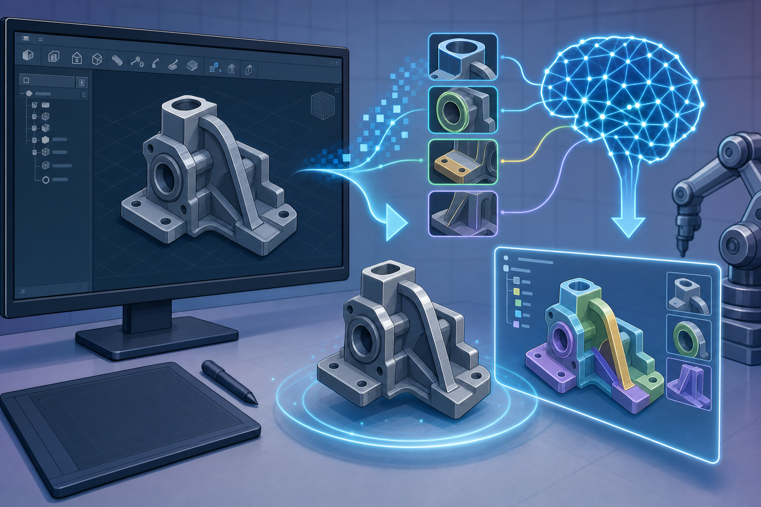
Modern CAD feels ordinary because it allows engineers to make a change and expect the model to remain meaningful: a hole remains a hole, a pocket remains bounded by faces, and a fillet either succeeds or fails for understandable geometric reasons. That expectation did not exist in the earliest years of computer-aided design. The first great transformation in design software was not simply the ability to draw on a screen, but the ability to represent objects so that software could reason about them. The essential breakthrough was the union of geometry, which describes mathematical shape, with topology, which describes how pieces of that shape connect to form edges, faces, shells, and solids. Before topology-aware kernels matured, early CAD systems could produce impressive visual descriptions of lines, arcs, curves, and surfaces, but those descriptions often lacked reliable engineering meaning. A model might look satisfactory on a display and still fail as a valid physical object. That gap between visual appearance and computable validity became one of the defining problems in the history of design software.
Geometry Without Reliable Physical Meaning
Wireframes, surfaces, and the ambiguity problem
The early CAD world was dominated by wireframe and surface descriptions because those representations matched what computers could reasonably calculate and display at the time. A wireframe model could define vertices connected by line segments and curves, giving a recognizable skeletal image of a bracket, housing, aircraft panel, or machine component. Surface modeling went further by allowing designers to describe skins, panels, and sculpted forms using mathematical patches. This was especially important in automotive and aerospace work, where companies such as General Motors, Lockheed, and Boeing needed accurate aerodynamic and aesthetic surfaces long before desktop solid modeling was practical. Yet wireframes and loose surfaces had a severe limitation: they did not necessarily say whether the apparent object was closed, manufacturable, or even logically consistent. A cube drawn as twelve edges looked like a cube, but the software might not know which side of each edge belonged to which face, whether all faces formed a closed shell, or whether the model contained duplicate or disconnected elements hidden by the viewpoint.
Why visual correctness was not enough
The difference between a drawing that looked right and a model that behaved right became painfully important as CAD moved from drafting assistance toward digital product definition. A machinist, numerical-control programmer, mold designer, or structural analyst needed more than a convincing image; they needed a representation that could survive downstream computation. Small gaps between surfaces could prevent toolpath generation. Overlapping edges could confuse intersection calculations. Dangling surface patches could make it impossible to determine inside from outside. Duplicate curves could create false boundaries that appeared harmless on screen but caused failure when a drawing was exported, meshed, or sectioned. These failures were not merely inconveniences. In an engineering environment, ambiguity propagates. A defective model may generate an incorrect mass property, an incomplete finite-element mesh, or an invalid cutter path. The software industry gradually learned that the screen image was the least demanding consumer of CAD data. The more serious question was whether the model carried a coherent structure that other algorithms could interrogate with confidence.
The Crucial Distinction Between Geometry and Topology
Shape versus connection
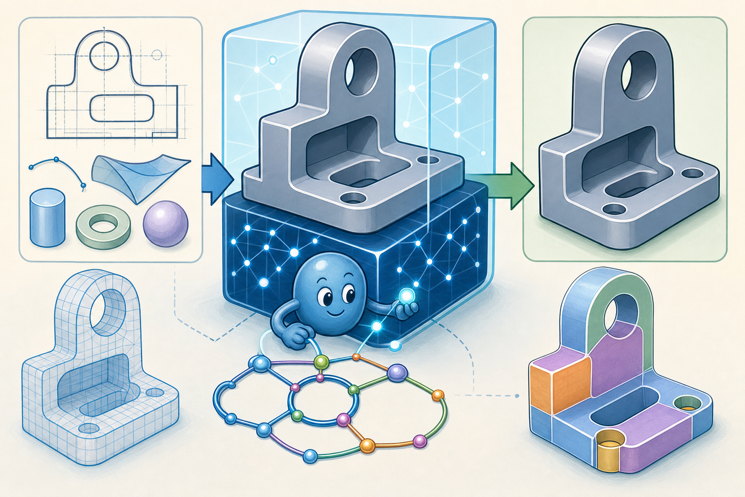
The distinction between geometry and topology is the conceptual key to understanding why CAD kernels became so important. Geometry describes shape: points in space, curves such as lines, arcs, splines, and conics, and surfaces such as planes, cylinders, cones, spheres, tori, and freeform patches. Geometry answers questions such as where a curve lies, how a surface bends, or what coordinates define a point. Topology describes structure: vertices, edges, coedges, loops, faces, shells, regions, and solids, together with the incidence relationships among them. Topology answers different questions: which edges bound a face, which faces meet at an edge, which loop forms a hole inside a face, and whether a collection of faces encloses a volume. A CAD model without strong topology can be visually rich yet computationally fragile. A CAD model with topology can support operations that require adjacency, orientation, enclosure, and identity. This is why topology-aware modeling transformed CAD from a digital sketching and surfacing tool into an engineering information system.
Historical roots of the problem
The pressure to solve this problem emerged from several strands of early computer graphics, numerical design, and manufacturing research. Ivan Sutherland demonstrated with Sketchpad at MIT in 1963 that interactive geometric constraint manipulation could be more than electronic drafting; it could become a new medium for design reasoning. In France, Pierre Bézier at Renault and Paul de Casteljau at Citroën developed mathematical curve and surface methods that became foundations for industrial shape definition. Their work helped automotive companies define smooth forms with precision, but it also exposed a deeper issue: smooth geometry alone did not guarantee a complete product model. At major industrial organizations, including MIT research groups, General Motors with its DAC efforts, Lockheed with CADAM-related production needs, and Boeing with increasingly complex aircraft definition workflows, the ambition was expanding beyond drawing automation. These groups wanted computers to support analysis, production, tooling, and configuration control. To do that, models had to become valid objects, not merely collections of mathematical fragments.
Why Solid Modeling Demanded Topology Awareness
A solid is more than surfaces
Solid modeling raised the stakes because a true solid model must answer a deceptively simple question: what volume does this object occupy? A collection of surfaces can suggest the answer, but unless the surfaces are connected, oriented, and complete, the software cannot reliably distinguish the inside from the outside. A block with a missing face is visually close to a block from many viewpoints, but it is not a closed solid. A cylindrical hole represented by a surface without properly connected circular edges may look like a hole, but downstream algorithms may not recognize it as a boundary of material removal. A valid solid required software to know which faces bounded the volume and how those faces met along edges and vertices. The model needed a consistent topological map, not just a catalog of equations. This is why topology-aware kernels became central to the rise of professional CAD. They supplied the structures and algorithms needed to maintain validity as the model was created, edited, combined, cut, blended, shelled, and exported.
Boolean operations exposed weak representations
Boolean operations made topology awareness unavoidable. Union, subtraction, and intersection appear conceptually simple because they mirror physical operations: add one body to another, remove material with a cutting tool, or keep only the common volume. Computationally, however, these operations require robust calculation of where surfaces intersect, how faces are split, which pieces remain, and how new loops, edges, and vertices are formed. When subtracting a cylinder from a block, for example, the system must intersect the cylindrical surface with the block faces, create circular or elliptical trimming curves, discard the interior material, and rebuild a valid boundary around the resulting hole. If the topology is inconsistent, the Boolean result may contain sliver faces, inverted normals, non-manifold edges, or open gaps. Designers often experienced these weaknesses as mysterious Boolean failures, but the underlying cause was usually the expression of a deep mathematical and structural challenge. The operation forced the CAD system to prove that it understood the object, not merely that it could display its outline.
Boundary Representation and the Engineering Model
How B-rep joined mathematics to structure
Boundary representation, commonly known as B-rep, became one of the dominant ways to represent solids because it joined precise mathematical geometry to explicit topological structure. In a B-rep model, a solid is described by its boundary: faces bounded by loops, loops made from oriented edges, edges associated with curves, and vertices associated with points. A face might lie on a plane, cylinder, cone, torus, or spline surface, while its boundaries define the trimmed region of that underlying surface that actually belongs to the solid. This separation is powerful. The mathematical surface can extend infinitely or beyond the useful area, while topology defines the portion that participates in the model. B-rep was particularly well suited to detailed engineering parts because manufactured objects are often defined by faces, holes, pockets, ribs, bosses, blends, drafts, slots, and intersections. Unlike a mere skin of disconnected surfaces, a coherent B-rep can answer questions about adjacency, enclosure, and orientation, which are indispensable for mass properties, section views, machining, meshing, and assembly interference checking.
The entities that made solids computable
The vocabulary of B-rep modeling may sound abstract, but each entity solved a practical engineering problem. Vertices anchor exact points where edges meet. Edges connect vertices and carry curve geometry, but they also express adjacency between faces. Loops define boundaries around faces, including outer loops and inner loops representing holes. Faces connect surface geometry to trimmed regions. Shells describe connected sets of faces, and a closed shell can define a solid region. This hierarchy allowed CAD systems to perform operations that earlier wireframe and surface systems struggled to support reliably. For example, when a designer applied a fillet to an edge, the kernel knew which two faces met there, what tangent conditions to satisfy, which adjacent edges needed trimming, and how to insert new blend faces into the model. This was a fundamental change in design software because the model was no longer a passive record of curves. It had a formal organization that algorithms could traverse, modify, validate, and repair.
- Geometry supplied the equations for curves and surfaces, including splines, analytic cylinders, planes, cones, spheres, and toroidal surfaces.
- Topology supplied the logical graph showing how vertices, edges, loops, faces, shells, and solids were connected and oriented.
- Modeling operations depended on both layers because an exact surface without correct connectivity could not produce a dependable engineering object.
CSG, PADL, and the Search for Solid Modeling Foundations
Primitive combinations and formal validity
Boundary representation was not the only path to solid modeling. Constructive Solid Geometry, or CSG, represented objects as combinations of primitives such as blocks, cylinders, spheres, cones, and wedges combined through Boolean operations. CSG was elegant because it stored a procedural construction tree: a part could be described as a block minus cylinders plus bosses and other primitive additions. This approach made membership classification conceptually clear, because the system could evaluate whether a point belonged inside or outside the resulting object by walking the Boolean tree. CSG also aligned with certain engineering mental models, especially for prismatic machined parts. However, CSG alone could become less convenient for the detailed boundary manipulation required in mature mechanical design, especially where blends, local face edits, sculpted boundaries, and imported surfaces played a major role. In practice, CSG and B-rep became competing and complementary ideas. Many systems used CSG-like feature histories while relying on B-rep structures to represent the evaluated result visible to the designer and usable by downstream applications.
Herbert Voelcker and PADL
A major academic influence came from the University of Rochester, where Herbert Voelcker and colleagues developed PADL, the Part and Assembly Description Language. PADL was important because it treated solid modeling as a problem requiring mathematical rigor, not merely interactive graphics. Voelcker’s work helped clarify issues of validity, regularized Boolean operations, and the need for representations that avoided pathological results. The language of “regularized” operations mattered because raw set operations on solids can generate dangling faces, isolated edges, or lower-dimensional remnants that have no physical manufacturing meaning. By insisting that operations return well-formed solids rather than arbitrary mathematical leftovers, solid modeling research moved closer to engineering reality. PADL also helped influence the intellectual climate in which commercial kernels later emerged. It demonstrated that digital product descriptions needed formal semantics: a model should not only be drawn but should represent a physically plausible object. This academic lineage is one reason solid modeling developed differently from ordinary graphics. CAD needed visual display, but its real ambition was computable manufacturing intelligence.
Romulus, ACIS, Parasolid, and the Commercial Kernel Era
Shape Data and the first commercial foundations
The commercial kernel era began when the industry recognized that robust modeling algorithms were too complex for every CAD vendor to reinvent independently. One of the pivotal companies was Shape Data in Cambridge, United Kingdom, which developed Romulus, widely recognized as one of the first commercial solid modeling kernels. Romulus provided reusable capabilities for B-rep solid modeling, Boolean operations, and topological management at a time when many CAD systems were still building proprietary solutions. Shape Data’s work had long-term consequences because its technology and personnel influenced later kernel development, including the lineage that led to Parasolid. The significance of Romulus was not merely that it made solid modeling commercially available. It helped establish the idea that the geometric modeling kernel could be a specialized software component, hidden beneath the CAD interface yet responsible for the deepest acts of model creation and modification. This separation of interface, application logic, and modeling engine shaped the architecture of CAD software for decades.
ACIS and Parasolid as hidden industrial infrastructure
Two commercial kernels became especially influential: ACIS and Parasolid. ACIS was developed by Spatial Technology, founded by figures including Richard Sowar, and became widely licensed across CAD, CAM, and engineering software markets. Parasolid grew from Shape Data technology and ultimately became owned by Siemens, where it formed a core modeling foundation for products such as Siemens NX and Solid Edge, while also being licensed to many other software vendors. These kernels delivered functions that users often took for granted: creating and editing curves, building surfaces, evaluating intersections, splitting faces, performing Boolean operations, generating fillets, shelling parts, offsetting surfaces, knitting imported geometry, and checking solid validity. The kernel became the hidden engine of CAD because every visible modeling command depended on a dense network of numerical methods, data structures, tolerances, and topological rules. When a user clicked “extrude cut,” the CAD interface appeared simple, but beneath that command the kernel had to create faces, trim boundaries, update loops, remove material, and return a coherent solid.
- Romulus demonstrated that a reusable commercial solid modeling kernel could serve multiple CAD applications rather than only one proprietary system.
- ACIS became a broad licensing platform used across design, manufacturing, and simulation software markets.
- Parasolid became one of the most influential B-rep modeling engines in mechanical CAD and remains central to many professional workflows.
What a Topology-Aware Kernel Actually Does
The kernel as geometric operating system
A geometry kernel can be understood as a specialized operating system for shape. It creates and modifies curves, surfaces, and solids, but its real value lies in maintaining consistency amid change. When a designer creates an extrusion, the kernel builds faces, edges, vertices, and orientation relationships. When the designer applies a fillet, the kernel computes rolling-ball or variable-radius blend surfaces, trims adjacent faces, inserts new topological entities, and removes or modifies old ones. When shelling a part, it offsets faces, extends and intersects offset surfaces, handles openings, and resolves corners where multiple offset faces meet. When importing a STEP file, it may need to heal tolerances, stitch surfaces into shells, identify gaps, and decide whether the body is closed enough to be treated as a solid. These tasks are difficult because CAD models combine exact intent with numerical approximation. Floating-point calculation, tolerance thresholds, nearly tangent intersections, tiny faces, and badly conditioned geometry can all threaten model validity. The kernel is where those threats are confronted.
Operations that depend on topology
The most familiar CAD commands are topology-intensive even when the user interface hides that fact. Boolean operations must classify pieces of faces as inside, outside, or on the boundary of another body. Fillets must identify chains of tangent edges and create new transitional faces. Offsets must preserve or rebuild adjacency while surfaces move normal to themselves. Trimming must connect curves on surfaces to loops that define face boundaries. Healing must determine whether nearby vertices should be merged, whether an open edge pair represents a gap, and whether face orientations are consistent. Intersections must produce curves that are accurate enough to support later operations. Draft analysis, wall-thickness checking, toolpath generation, drawing section views, and finite-element meshing all rely on topological coherency. The kernel therefore does not merely “draw 3D.” It preserves a model’s status as an engineering object through repeated transformations. A visually appealing model that fails topological validation is a liability; a topology-aware model can participate in an entire product-development chain.
- Boolean operations require splitting, classifying, discarding, and reconnecting faces, edges, loops, and vertices.
- Filleting and blending require stable knowledge of which faces meet along which edges and how new transitional faces should be inserted.
- Shelling and offsetting require robust handling of face offsets, corner intersections, self-intersections, and topological reconstruction.
- Import healing requires converting imperfect exchanged geometry into usable solids that downstream tools can trust.
Parametric Modeling and the Hard Problem of Stable References
Feature history changed the expectations
The arrival of history-based, parametric, feature-oriented CAD made topology awareness even more consequential. PTC Pro/ENGINEER, introduced by Parametric Technology Corporation in the late 1980s, helped popularize a radically different workflow: designers could build parts as ordered features controlled by dimensions, constraints, and relationships, then regenerate the model when parameters changed. This was a major cultural shift. Instead of manually redrawing geometry, engineers could encode design intent in a history tree. A hole could be placed relative to an edge, a boss could depend on a sketch, and a pattern could update when a dimension changed. However, this workflow depended on the CAD system’s ability to identify model entities across rebuilds. If an earlier feature changed enough to split a face, delete an edge, or merge two regions, later features referencing those entities might fail. The model had to remember not simply coordinates, but identity. In history-based CAD, topology became a language of memory as well as structure.
The naming problem
The “naming problem” became one of the classic unsolved irritants of parametric modeling. When a face is split into two faces after a design change, which new face inherits the original name? When two faces merge, which identity survives? If a fillet consumes an edge that a later chamfer referenced, what should happen to the downstream feature? The issue sounds administrative, but it is deeply geometric and topological. CAD systems must infer continuity of design intent from evolving model structure. Commercial systems developed many strategies: persistent identifiers, feature ownership records, geometric matching, topological signatures, dependency graphs, and user-visible repair tools. Products such as Dassault Systèmes CATIA, Siemens NX, SolidWorks, Autodesk Inventor, and PTC Creo all had to wrestle with this problem because every professional parametric system lives under the threat of lost references. A robust kernel helps by producing consistent topology, but the naming problem also crosses into feature management, constraint solving, regeneration logic, and user-interface design.
Why Downstream Engineering Forced Better Solids
Manufacturing, simulation, drawings, and inspection
Topology-aware modeling became indispensable because CAD data no longer stayed inside the design department. Manufacturing software needed valid faces and edges for toolpath selection, cutter contact calculation, stock removal simulation, and feature recognition. Analysis software needed coherent solids or watertight surface regions for meshing, load application, boundary conditions, and material property calculation. Drawing generation needed reliable section cuts, hidden-line removal, projected views, and associativity between model edges and drawing annotations. Inspection software needed measurable surfaces and well-defined nominal geometry. Assembly systems needed interference detection, clearance analysis, mating references, mass properties, and collision checks. Additive manufacturing added another demand: 3D printing workflows required closed, consistently oriented shells to determine printable volumes, even when the data arrived through STL or mesh representations rather than native B-rep. Each downstream use punished ambiguity differently, but the root requirement was the same. A model had to be more than visually plausible. It had to sustain repeated computational questions, each depending on the correct relationship between geometric shape and topological structure.
How kernels shaped the broader software ecosystem
The influence of commercial kernels extended far beyond the obvious CAD applications. Because Parasolid and ACIS were embedded into many CAD, CAM, CAE, inspection, and visualization products, they created a shared infrastructure across the design-software market. This had practical consequences. If multiple applications used the same kernel, data translation could be more reliable, because the receiving system understood similar modeling assumptions. A Parasolid-based CAD system exporting a native Parasolid file to a Parasolid-based simulation or manufacturing tool could often avoid some of the translation damage associated with neutral formats. ACIS SAT files played a similar role in certain ecosystems. At the same time, dependence on kernels meant that the strengths and weaknesses of kernel algorithms visibly shaped user experience across many branded products. A fillet failure, a successful shell, a fragile imported body, or a remarkably stable Boolean cut often reflected kernel behavior beneath the application interface. The hidden kernel became a competitive differentiator, a licensing strategy, and a technical foundation for whole software families.
The Industry Learned That Validity Is a Product Feature
Reliability became part of design productivity
As CAD matured, users learned to value not just a long list of modeling commands but the reliability with which those commands worked on difficult geometry. A system that could create a demo part was less valuable than one that could survive a real production model with hundreds of features, imported supplier geometry, small blends, draft angles, thin walls, and last-minute dimensional changes. This is why professional CAD vendors invested heavily in kernel development, geometry testing, and model-healing tools. Dassault Systèmes built CATIA into a dominant aerospace and automotive platform partly because it could support complex surfacing and large-scale product definition. Siemens strengthened NX and Solid Edge around Parasolid and related infrastructure. SolidWorks brought Parasolid-based mechanical modeling to a broader Windows market. Autodesk Inventor and other Autodesk products depended on advanced modeling components to compete in mainstream mechanical design. The common theme is that topology-aware behavior became a product-quality issue. If the model failed to rebuild, machine, mesh, or translate, productivity collapsed no matter how attractive the interface looked.
The invisible labor behind ordinary commands
The remarkable fact about topology-aware kernels is how invisible their achievement became. A designer selecting an edge and applying a radius may not think about trimmed parametric surfaces, edge-face adjacency, tolerance negotiation, or topological Euler operators. An engineer shelling a plastic enclosure may not think about offset singularities, corner blends, or self-intersection removal. A product-development team importing a supplier’s STEP file may not think about sewing algorithms, orientation correction, or gap closure. Yet every one of those ordinary actions depends on decades of research and industrial refinement. The history includes academic work in solid modeling theory, industrial surface mathematics from automotive pioneers, commercial kernel engineering by Shape Data, Spatial Technology, Siemens, and others, and the pressure of users in aerospace, machinery, industrial equipment, consumer products, and architecture. The result is software that often appears simple precisely because its internal machinery is sophisticated. Topology-aware kernels made CAD trustworthy enough to become infrastructure rather than novelty.
Topology Turned CAD Models Into Engineering Objects
The lasting transformation
The decisive contribution of topology-aware kernels was not prettier three-dimensional graphics. It was the creation of models that software could reason about. A topology-aware CAD system can ask whether a body is a closed solid, which faces meet at a selected edge, what faces define a pocket, what changes when a hole moves, whether a Boolean cut leaves a valid region, and whether an imported model can be machined, simulated, printed, inspected, or assembled. These questions define the difference between digital drawing and digital engineering. The history of design software shows that visual representation was only the first step. The deeper revolution was semantic and structural: CAD models became objects with boundaries, identities, relationships, and behaviors. Today’s users may rarely think about B-rep graphs, face-edge connectivity, shell orientation, regularized Booleans, or persistent topological naming, but they depend on them constantly. Every reliable fillet, shell, Boolean subtraction, associative drawing view, STEP import, toolpath operation, clash check, and parametric rebuild carries the legacy of this work.
The foundation beneath modern product development
Topology remains one of the invisible foundations of modern product development because it lets independent software systems treat a CAD model as something more durable than a picture. Product visualization can shade it, simulation can mesh it, manufacturing can cut it, inspection can measure it, additive workflows can evaluate its watertightness, and assembly systems can test how it fits with neighboring parts. None of those workflows would be dependable if CAD models were only collections of disconnected mathematical surfaces. The achievement came from decades of work by researchers, industrial mathematicians, kernel developers, and CAD companies that recognized a fundamental truth: engineering software must understand structure as well as shape. The names associated with this evolution, including Ivan Sutherland, Pierre Bézier, Paul de Casteljau, Herbert Voelcker, Shape Data, Spatial Technology, Siemens, PTC, Dassault Systèmes, Autodesk, and many others, mark a long movement from graphics toward computable design intent. In that movement, topology-aware geometric modeling became one of the quiet technologies that made modern engineering possible.
Also in Design News