
Your Cart is Empty


Large-Scale Assembly Performance Strategies for Modern CAD Workflows
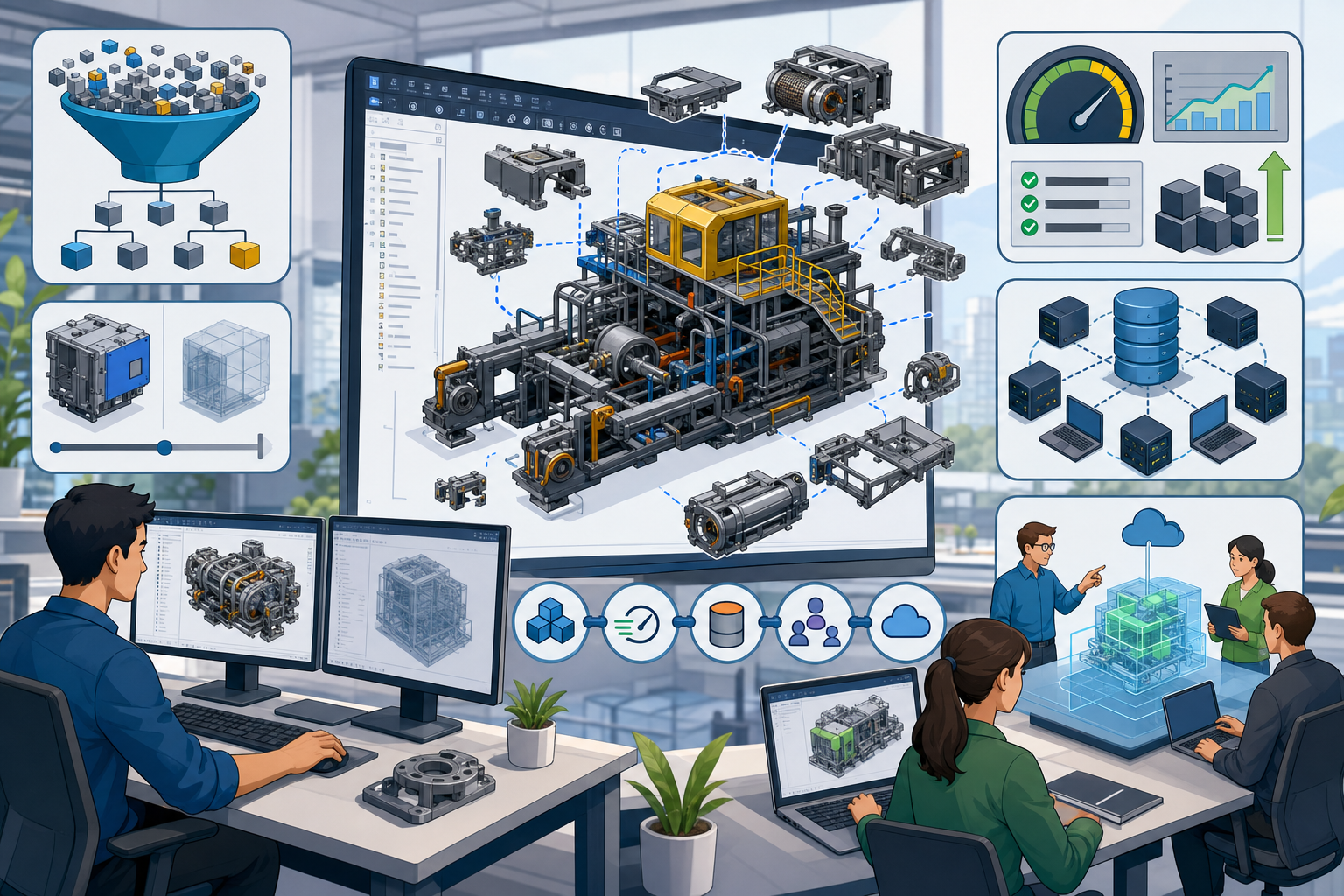


Large-scale assemblies expose the difference between software that can display geometry and software that can support decisions. In advanced design environments, the assembly is no longer a static collection of parts; it is a living interface between engineering intent, supplier data, manufacturing planning, simulation, visualization, and operational maintenance.
Why Large-Scale Assemblies Break Traditional CAD Workflows
Defining Scale in Contemporary Design Environments
In modern product development, “large-scale” no longer means only a file that takes a long time to open. It refers to assemblies whose structure, relationships, configurations, and data dependencies exceed the assumptions of traditional desktop CAD workflows. An aerospace structure may include millions of components distributed across fuselage sections, propulsion systems, avionics bays, interior modules, fastening systems, and service access zones. An automotive platform may include multiple powertrain variants, regional compliance packages, trim levels, manufacturing options, and supplier modules that must coexist in one managed product definition. Industrial machinery may combine internally designed frames, purchased actuators, electrical cabinets, guarding, hydraulic systems, and supplier-driven subassemblies that arrive with inconsistent modeling quality. In BIM/CAD hybrid environments, the challenge becomes even more complex because buildings, production equipment, utility infrastructure, robotics, platforms, and process layouts may need to be coordinated in the same spatial context. A large assembly is therefore not simply large in file size; it is large in geometric density, configuration complexity, reference depth, and organizational responsibility.
- Aerospace assemblies often stress CAD systems through extreme component count and tightly controlled spatial interfaces.
- Automotive programs create scale through configuration variation and platform reuse.
- Industrial machinery introduces supplier inconsistency, repeated hardware, and mixed mechanical-electrical data.
- BIM/CAD hybrid projects combine architectural context with high-detail manufactured equipment.
Where Performance Bottlenecks Actually Begin
The most visible symptom of a large assembly problem is slow interaction, but the cause is usually distributed across several layers of the CAD environment. Excessive geometric detail is the obvious starting point: detailed threads, embossed logos, internal pump cavities, full bearing models, spring coils, textured fasteners, and cosmetic fillets force the system to load and tessellate information that contributes little to top-level decision-making. Feature histories add another burden, especially when parts contain long parametric chains, imported repairs, pattern-heavy details, or references to unstable upstream geometry. At the assembly level, thousands of mates, constraints, inherited coordinate systems, equations, and external references can create expensive rebuild operations that are difficult to predict. Supplier models are often especially problematic because they may contain internal mechanisms, hidden bodies, microscopic faces, unnecessary metadata, and surfaces generated by translation errors. Even when the model is geometrically valid, the graphics pipeline may become overloaded by tessellation, real-time shadows, transparency, section caps, textures, anti-aliasing, and edge display. The workstation may appear underpowered, but the deeper issue is often uncontrolled geometric and relational complexity.
- High-detail geometry increases memory consumption and graphics processing load.
- Heavy feature histories slow regeneration and make changes risky.
- Large constraint networks increase solve time and failure probability.
- Imported supplier data often contains hidden geometry that has no value in top-level layout.
- Visualization effects can degrade performance even when the engineering model is well structured.
Performance as an Organizational Problem
Assembly performance is frequently treated as an IT issue, but its consequences are deeply connected to design quality and business speed. When a full product model takes twenty minutes to open, engineers stop exploring alternatives because every change carries a waiting cost. When regenerations are unpredictable, designers postpone improvements, avoid restructuring, or work around known errors instead of correcting them. Design reviews become less interactive because the presenter relies on static screenshots, isolated exports, or outdated lightweight copies instead of navigating the current assembly in real time. Downstream teams may receive simplified data that was created manually months earlier, meaning simulation, manufacturing, service planning, and visualization teams work from models that no longer reflect design intent. Collaboration also becomes unequal when only a few high-end workstations can open the entire assembly, causing knowledge to concentrate around the individuals with access to the most powerful hardware. The result is not merely inconvenience; it is a measurable reduction in iteration velocity, engineering confidence, and cross-disciplinary alignment.
Core Software Strategies for High-Performance Assembly Management
Lightweight Loading as a Design Navigation Strategy
High-performance assembly management begins with the recognition that not every component needs to be fully editable all the time. Lightweight loading techniques allow CAD platforms to represent components at different levels of fidelity depending on the task. Suppressed components remove irrelevant parts entirely from memory, which is useful when a designer is working on a specific subsystem and does not need the surrounding product definition active. Lightweight parts preserve enough information for positioning, mass properties, and basic reference while deferring feature-level loading until required. Graphics-only representations allow rapid navigation during reviews by displaying tessellated bodies without resolving parametric features. Bounding boxes are even more abstract, but they are extremely effective for packaging, clearance, transportation envelopes, and early spatial coordination. Level-of-detail models create controlled alternatives, such as full engineering detail, simplified external skins, service envelopes, and installation volumes. Selective loading by zone, system, or discipline is particularly important for aircraft, ships, factories, and infrastructure projects where the designer’s field of work is spatially bounded. The most mature workflows treat lightweight loading not as a compromise, but as task-specific model intelligence.
- Use suppressed states for components irrelevant to the current design task.
- Use lightweight parts when positional accuracy matters but feature editing does not.
- Use graphics-only models for fast review, walkthrough, and communication sessions.
- Use bounding boxes for packaging studies, transportation planning, and reserved volumes.
- Use zone-based loading for physically large products and facilities.
Configuration and Representation Management
Configurations are often introduced as a convenience for variants, but in large assemblies they become a central performance strategy. A design configuration may expose the engineering detail required to edit interfaces, control fastening strategy, review tolerance-critical regions, or validate mechanisms. A manufacturing configuration may suppress decorative features, show fixture access, replace purchased components with process-relevant envelopes, and expose weld preparations, machining allowances, or assembly sequence states. A service configuration may prioritize clearance zones, removable panels, tool access, consumable components, inspection ports, and maintainability paths. Visualization configurations may replace parametric detail with optimized mesh data, material assignments, simplified interiors, and scene-ready surfaces for product communication. Simulation-ready configurations may remove small features, suppress fasteners, close gaps, idealize sheet metal, replace complex components with mass properties, and simplify contact regions for CAE workflows. These configurations should not be unmanaged duplicates; they should be deliberate representations with clear ownership, naming logic, release status, and update rules. The objective is to prevent teams from making unofficial copies simply because the master model is too heavy. Good representation management makes the right version of the assembly available for the right decision at the right time.
- Engineering configurations preserve design intent and editable detail.
- Manufacturing configurations support process planning and fixture development.
- Service configurations emphasize access, replacement paths, and maintainability.
- Visualization configurations optimize interaction, appearance, and communication.
- Simulation configurations reduce geometry to what the solver actually needs.
Intelligent Data Referencing and Modular Control
Large assemblies fail when every component depends on everything else. Intelligent data referencing introduces modular control so that changes can propagate where needed without creating fragile update chains. External references are powerful because they support associative design, but they must be designed with clear boundaries. In a top-down approach, master geometry, skeleton models, layout sketches, reference planes, and interface envelopes define the important relationships before detailed parts are built. This is valuable when product architecture, packaging, or styling surfaces drive downstream components. In a bottom-up approach, independently mature parts are assembled into larger systems, which is efficient for standard hardware, catalog components, supplier equipment, and reusable modules. Most advanced workflows blend both approaches: skeleton models control critical interfaces, while stable parts remain self-contained. Assembly envelopes are especially useful because they reserve space, protect clearance, and communicate responsibility without requiring full-detail geometry. Dependency mapping then becomes essential. Teams need to know which models drive other models, which references are locked, which are allowed to update, and which are obsolete. Without this discipline, a harmless-looking edit in a reference component can trigger rebuild failures throughout the product.
- Use skeleton models to define shared interfaces without loading every downstream feature.
- Use master geometry for critical planes, axes, envelopes, and functional layouts.
- Use assembly envelopes to coordinate space between disciplines and suppliers.
- Limit external references to intentional, documented relationships.
- Map dependencies to identify fragile update paths before they become production risks.
Graphics and Compute Acceleration
Software acceleration matters, but it delivers the best results when paired with disciplined model structure. GPU-accelerated visualization can dramatically improve rotation, panning, sectioning, shading, and real-time walkthroughs, particularly when the CAD platform uses modern graphics APIs and well-optimized tessellation caching. Multi-threaded rebuilds, where supported, can reduce computation time for independent features or components, although many parametric operations remain sequential because one feature depends on the result of another. Cached tessellation data is often underestimated; when a system does not need to regenerate display meshes every time an assembly opens, review and navigation become substantially faster. Cloud streaming offers another path for massive model review, particularly for distributed teams that need access without transferring multi-gigabyte assemblies to local machines. Server-side model processing can generate derivatives, thumbnails, simplified views, clash data, and neutral visualization formats automatically for collaboration platforms. However, acceleration cannot rescue a chaotic product structure indefinitely. It should be viewed as a multiplier for robust CAD architecture, not a substitute for modeling discipline. The strongest environments combine GPU performance, cached representations, cloud-native access, and well-governed assembly data.
Practical Design Process Techniques for Keeping Assemblies Responsive
Modeling Discipline at the Component Level
The fastest large assemblies usually come from disciplined component modeling long before anyone opens the top-level product. Designers should avoid including unnecessary fillets, modeled threads, microscopic engraving, decorative chamfers, springs, internal electronics, ball bearings, and fasteners in working views unless those details are directly relevant to the current task. Fillets and rounds are often essential for manufacturing, stress, ergonomics, or aesthetics, but they do not need to be active in every assembly context. Threads should typically be represented cosmetically or by simplified cylinders unless thread engagement is being analyzed. Supplier models should be simplified aggressively, especially when internal geometry contributes nothing to packaging or interface control. One useful principle is to separate design intent geometry from manufacturing detail: the external mounting faces, connection points, clearance zones, and mass properties may be critical, while internal ribs, seals, pins, and screws may be irrelevant at the top level. Repeated components should be represented with substitute parts or optimized instances when possible. High-cost features should be suppressed in working configurations and released into full-detail states only when necessary.
- Suppress cosmetic fillets in working configurations unless they affect clearance or function.
- Use cosmetic threads or simplified cylinders instead of detailed helical geometry.
- Replace repeated fastener stacks with simplified arrays or pattern-aware representations.
- Remove supplier-model interiors that do not affect installation, access, or performance.
- Maintain separate configurations for design, manufacturing, simulation, and visualization use.
Assembly Structure Based on Function and Space
Many performance problems are amplified by assembly structures that reflect departmental ownership rather than product logic. A large product should be organized around functional systems, physical zones, and stable interfaces so that designers can load exactly what they need. For example, an industrial machine may be organized into frame, drive, guarding, tooling, pneumatics, controls, service access, and installation modules rather than one enormous mechanical folder. A ship, aircraft, factory, or process plant may require spatial zones such as deck, bay, line, cell, wing section, utility corridor, or equipment room. This allows teams to review interference, access, and installation constraints without loading the entire project. Frequently edited components should be isolated from stable reference geometry so that small changes do not force unnecessary rebuilds across the whole assembly. Interface components, mounting plates, layout skeletons, and envelope models should be stable, named clearly, and released carefully. Naming conventions and metadata standards are not administrative decoration; they enable automation, filtering, selective loading, ownership tracking, and search. A well-structured assembly behaves like a product map rather than a digital storage pile.
- Structure assemblies by functional systems whenever possible.
- Create zone-based assemblies for products that are physically large or spatially complex.
- Keep active design areas separate from stable reference modules.
- Use clearly named interface parts to control shared boundaries.
- Apply consistent metadata for system, zone, owner, maturity, supplier, and release status.
Collaboration, Ownership, and Data Governance
Large-assembly performance cannot be sustained if teams rely on uncontrolled copies. Once engineers begin copying major assemblies to local drives because the managed version is too slow, the organization loses control over references, release states, supplier updates, and design decisions. PLM or PDM discipline is therefore a performance tool as much as a compliance tool. Check-in and check-out workflows prevent conflicting edits, while revision control offers visibility into which assemblies are released, in work, obsolete, or under review. Teams should explicitly track lightweight versus fully resolved states because a design decision made on a simplified model may not be valid if hidden internal details later reappear. Ownership of subassemblies and reference interfaces must be defined clearly. If one team owns the conveyor envelope and another owns the guarding, both must know which geometry is authoritative and how interface changes are approved. Release states also protect the wider organization from unstable data. An experimental subassembly with unresolved constraints, broken references, or oversized supplier imports should not automatically flow into every top-level review. Good governance makes the large assembly more predictable, more trustworthy, and easier to open.
- Avoid local uncontrolled copies of major assemblies.
- Use PDM or PLM to manage ownership, revisions, maturity, and release state.
- Track whether decisions were made using full, lightweight, or simplified representations.
- Define authoritative owners for shared interfaces and skeleton geometry.
- Prevent unstable work-in-progress data from degrading the performance of larger teams.
Automation Opportunities for Scalable Assembly Health
Manual cleanup is rarely enough once assemblies reach enterprise scale. Automation can convert good intentions into repeatable practice. Scripts can suppress nonessential components based on metadata such as system, zone, mass, supplier, release status, or component type. Imported supplier models can be processed through automated cleanup routines that remove tiny faces, hidden bodies, internal cavities, duplicate solids, excessive detail, and invalid entities. Rule-based simplification can generate envelope models, bounding boxes, exterior skins, and defeatured variants without requiring an engineer to rebuild the same simplification logic by hand. Batch conversion to visualization formats can make lightweight review data available to manufacturing planners, executives, service teams, and suppliers who do not need native CAD access. Assembly health dashboards are especially valuable because they make performance visible. Instead of waiting until an assembly becomes unusable, teams can track rebuild time, open time, memory usage, file size, tessellation size, number of constraints, broken references, circular dependencies, imported-body count, and configuration errors. Over time, these metrics create a culture where assembly responsiveness becomes measurable engineering quality, not an afterthought addressed only during project crises.
- Create scripts that suppress components by zone, discipline, maturity, or task.
- Automate cleanup of imported supplier geometry before release into the main assembly.
- Generate simplified representations using repeatable rules rather than manual remodeling.
- Convert native CAD into optimized visualization formats through scheduled batch jobs.
- Monitor assembly health using dashboards for rebuild time, file size, references, and errors.
Conclusion: Performance as a Design Capability
Beyond Faster Hardware
Managing large-scale assemblies is no longer just a matter of purchasing faster CPUs, more memory, and professional GPUs, although hardware still matters. The scale and complexity of modern products require a deliberate combination of smarter CAD data structures, lightweight representations, modular product architecture, disciplined modeling behavior, and connected data management. A workstation can accelerate graphics and computation, but it cannot determine which supplier details are irrelevant, which external references are fragile, which configuration should support service planning, or which assembly zone should be loaded for a packaging review. These are design-process decisions. The best-performing teams therefore treat performance as part of product architecture. They design assemblies so that information is available at the fidelity required for the task, not at the maximum fidelity possible. They define ownership, simplify responsibly, automate repetitive cleanup, and monitor assembly health before performance failures become cultural habits. Their goal is not merely to open the model faster; it is to preserve the ability to think, test, communicate, and change while the product is still evolving.
The Value of a Responsive Product Model
A responsive large assembly changes the behavior of the organization around it. Design reviews become more exploratory because teams can section, filter, isolate, measure, and compare alternatives in real time. Engineering changes become less intimidating because rebuilds are predictable and component relationships are understandable. Cross-disciplinary collaboration improves because mechanical, electrical, architectural, manufacturing, simulation, service, and visualization teams can access appropriate representations without waiting for specialized operators to prepare static exports. Packaging conflicts and interference issues can be detected earlier because spatial context remains usable throughout the project rather than being opened only at formal milestones. Handoffs to simulation, manufacturing, and visualization become more reliable when simplified models are generated from governed configurations rather than from disconnected manual copies. Most importantly, assembly performance supports design confidence. When the model responds quickly, engineers ask better questions, compare more options, and challenge assumptions earlier. In that sense, large-assembly performance is not an efficiency feature; it is a design capability that directly affects quality, speed, and technical risk.
The Next Evolution of Large Assembly Management
The future of large assembly management will depend on platforms that understand product context as well as geometry. AI-assisted simplification will increasingly identify which features can be removed for a given task while preserving interfaces, mass properties, clearance requirements, and manufacturing intent. Cloud-native model streaming will allow teams to review massive assemblies without transferring every native file to every workstation, making access more inclusive across locations and disciplines. Automated dependency analysis will expose fragile references, circular update paths, high-cost rebuild chains, and obsolete interface geometry before they disrupt production work. Design platforms will also become more aware of role-specific needs, offering different representations to a simulation analyst, manufacturing engineer, service planner, supplier, architect, or visualization artist from the same governed product definition. The long-term direction is clear: assembly management will move from manual loading decisions toward intelligent, context-aware representation control. Teams that prepare for this future by adopting modular architecture, metadata discipline, simplified configurations, and measurable performance standards will gain more than faster models. They will gain a more resilient design process capable of handling the complexity of next-generation products, factories, infrastructure, and systems.
Also in Design News






