
Your Cart is Empty


Design Software History: Boolean Operations and the Origins of Solid Modeling


Before “Solid” Modeling: Why Boolean Thinking Became Necessary
The limits of drawing-based computation
Boolean operations became necessary because early computer-aided design could describe appearance more easily than physical reality. The first generations of CAD systems were powerful drafting aids, but much of their value still belonged to the world of lines, arcs, dimensions, layers, and projected views. A 2D drawing could communicate intent to a machinist or architect, and a wireframe model could suggest depth on a screen, yet neither representation reliably answered the questions engineers increasingly wanted software to answer. Is this bracket a closed, physically valid object? What is its exact volume and weight? Will this gear housing collide with a nearby shaft? If a cylindrical hole is drilled through a block, which material has actually been removed? These are not merely visualization questions. They are questions about matter, occupancy, and spatial logic. The move from drafting to modeling required CAD to stop being only a display system and become a reasoning system.
From visible shape to computable matter
Wireframe modeling, common in early interactive graphics, could represent vertices and edges but often left the computer ignorant of what was inside and what was outside. Surface modeling improved visual richness by describing skins, patches, and sculpted forms, but surfaces could still be open, overlapping, self-intersecting, or disconnected in ways that made engineering computation unreliable. A beautiful surface model might render well and still fail to define a watertight volume. For industrial design, aerospace fairing, and automotive bodywork, surfaces were indispensable; for machining a sealed casting, analyzing mass properties, or checking clearance in an assembly, the system needed a more rigorous definition of a solid. The conceptual leap was to treat objects as sets of points in three-dimensional space. Once a part is understood as a set, the crucial manufacturing actions can be expressed as logical operations on those sets.
The manufacturing language of union, subtraction, and intersection
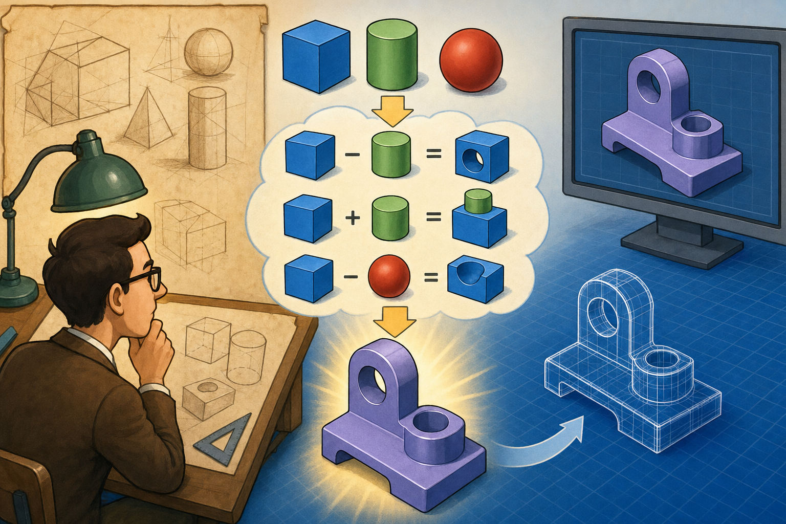
Boolean operations became the natural language of physical design because they mirrored what manufacturing already did. A union joins material volumes, just as welding combines plates, casting fills a cavity, or an additive process deposits one region of material onto another. A difference, often called subtraction, removes one volume from another, just as milling cuts a pocket, drilling creates a hole, turning removes stock from a rotating workpiece, or trimming cuts away excess material. An intersection identifies the volume two solids share, which is essential for collision detection, mold cavity reasoning, tooling envelopes, die design, and extracting domains for simulation. These operations gave CAD a vocabulary that was far closer to the workshop than to the drafting table. Instead of drawing four circles to indicate drilled holes, a designer could define cylinders that cut through a block and expect the software to understand the resulting solid.
Why Boolean logic fit industrial reasoning
The deeper importance of Booleans is that they connected design intent to manufacturable consequence. A drilled hole is not only a circle on a face; it is a volume removed along an axis, with a boundary, a depth, and possible intersections with other features. A boss on a casting is not merely an outline; it is an added volume that changes mass, stiffness, machining stock, and tool accessibility. Mold and die work depends even more heavily on this logic because the cavity, core, parting line, shutoff surfaces, and extracted part all relate through combinations and separations of volumes. Boolean thinking allowed software to formalize these relationships. It made possible a style of CAD in which the computer could participate in engineering judgment by evaluating containment, adjacency, validity, interference, and material continuity.
- Union corresponds to adding or combining material, as in welding, casting buildup, bosses, ribs, pads, and additive manufacturing deposition.
- Difference corresponds to material removal, as in drilling, milling, boring, trimming, punching, and machining stock reduction.
- Intersection corresponds to shared space, as in collision checking, die closure analysis, mold cavity extraction, and simulation domain creation.
Intellectual roots before commercial solid modeling
The word “Boolean” reaches back to George Boole, the nineteenth-century mathematician whose algebra of logic transformed truth values into symbolic operations. Boole was not thinking about CAD, of course, but his algebra supplied the distant intellectual ancestor for operations such as AND, OR, and NOT. In geometric modeling, these ideas became operations on spatial sets: intersection, union, and complement or difference. During the 1960s and 1970s, researchers in computational geometry, computer graphics, and mechanical design began turning this logical language into algorithms that could work on geometric entities. Ivan Sutherland’s Sketchpad, created at MIT in 1963, was not a modern solid modeler, but it was a crucial precursor because it demonstrated interactive graphical design, constraints, object instances, and a new relationship between human intention and computational geometry. Sketchpad helped prove that the computer could become an active design medium, not just a calculation machine.
Constructive Solid Geometry and the First Boolean-Centered Modelers
The CSG idea: objects as expression trees
Constructive Solid Geometry, usually abbreviated as CSG, made Boolean operations central to the identity of the model. In a CSG system, a part is represented as a tree of primitive shapes and operations. The leaves of the tree are simple solids such as blocks, cylinders, cones, spheres, wedges, toruses, and swept profiles. The internal nodes are Boolean operations: union, difference, and intersection. A simple mechanical part might be represented as a rectangular block minus four cylinders for bolt holes, plus a cylindrical boss, minus a smaller cylinder for a through bore, with ribs added by union and trimmed by intersection with cutting planes or tooling volumes. This mattered because the model was not merely a mesh or collection of patches. It was a mathematical recipe describing how a valid volume was constructed from known valid volumes.
Why early researchers found CSG attractive
CSG appealed to early solid modeling researchers because it was compact, rigorous, and closely aligned with engineering operations. A complicated part could sometimes be stored as a relatively concise tree rather than as an exhaustive list of every face, edge, and vertex created by every cut. The structure also preserved a form of design history. If a hole was represented as a cylinder subtracted from a block, the software retained the fact that the hole came from an operation rather than merely from a ring of edges on a face. This made CSG feel intuitive to people who thought in terms of machining, fixtures, stock, and tooling. It also avoided many ambiguities of wireframe drawings, where a collection of lines might correspond to several possible three-dimensional interpretations. In CSG, if the primitives and operations were valid, the intended solid was usually more mathematically explicit.
Common CSG construction patterns
The strength of CSG was clearest in parts dominated by regular engineering features. Blocks, cylinders, cones, and swept profiles naturally described mechanical components such as brackets, housings, fixtures, flanges, shafts, pulleys, and manifolds. A modeler could begin with raw stock, subtract pockets and holes, add bosses and pads, and intersect the result with limiting volumes. In this sense, CSG acted almost like a symbolic manufacturing plan. It did not simulate a milling cutter in full detail, but it encoded the conceptual pattern of adding and removing matter. The tree could also support parameter changes: increasing the diameter of a subtracted cylinder enlarged a hole; moving the primitive changed the hole location; suppressing a union removed a boss. These capabilities anticipated the later importance of history-based parametric modeling in systems such as Pro/ENGINEER from Parametric Technology Corporation, introduced in the late 1980s.
- A mounting plate could be represented as a block with cylinders subtracted for bolt holes.
- A cast housing could be represented as joined volumes, hollowed by subtracting internal cavity shapes.
- A ribbed support could be represented through unions of thin swept volumes and trimming intersections.
- A mold cavity could be derived by subtracting a part volume from a larger tooling block.
MAGI, SynthaVision, and commercial CSG visibility
One of the best-known early commercial CSG-related systems was SynthaVision, developed by Mathematical Applications Group, Inc., commonly known as MAGI. Founded by Philip Mittelman and colleagues, MAGI gained attention for using solid modeling techniques in simulation and visualization, including work connected to radiation analysis and later computer graphics for film and technical visualization. SynthaVision represented objects through combinations of primitive solids and Boolean operations, making it an important demonstration that CSG was not only an academic abstraction. It could support visualization, analysis, and industrial communication at a time when computing resources were highly constrained. MAGI’s work also showed that solid modeling could serve multiple communities: engineers wanted physical correctness, animators wanted coherent volumes and shading, and analysts wanted meaningful spatial occupancy. The shared requirement was a model that knew more than a drawing knew.
PADL and the Rochester school of solid modeling
The PADL project at the University of Rochester was one of the landmarks of solid modeling research. Led by Herbert Voelcker, with major contributions from Aristides Requicha and others, PADL explored how solids could be represented, validated, and computed with enough rigor for engineering use. Voelcker and Requicha were especially influential in clarifying the mathematical foundations of solid modeling, including regularized set operations. Regularization was essential because naïve set operations could produce dangling faces, isolated edges, or lower-dimensional fragments that did not correspond to manufacturable solids. By insisting that Boolean results should be proper solids, not arbitrary mathematical leftovers, the Rochester researchers helped define what industrial solid modeling needed to become. Their work influenced the language, assumptions, and expectations of later CAD kernels, especially the idea that a modeler must preserve solidity and topological validity after operations.
BUILD, Ian Braid, and the bridge to boundary algorithms
At Cambridge, Ian Braid and his colleagues developed BUILD, another landmark system in the history of solid modeling. BUILD is frequently associated with advances in boundary representation and Boolean algorithms, and it helped shape the transition from purely constructive descriptions toward explicitly stored faces, edges, and vertices. This transition was not a simple replacement of one method by another. CSG was excellent as a high-level recipe, but many practical tasks required evaluated boundaries. To display a shaded image, compute mass properties, generate toolpaths, or export geometry to another system, the software needed to know the actual surfaces and curves that formed the boundary of the result. BUILD and related research helped establish that robust solid modeling required both logical operations and careful boundary evaluation. In practice, the future belonged to systems that could combine design history with evaluated geometry.
Romulus and the commercial kernel lineage
Romulus, developed by Shape Data in the United Kingdom, became one of the early commercial solid modeling kernels and a major influence on later CAD infrastructure. Shape Data, founded by figures including Ian Braid, Charles Lang, and Alan Grayer, helped turn research-grade geometric modeling into reusable industrial software. Romulus provided solid modeling capabilities that could be licensed and embedded by CAD vendors, helping establish the kernel as a distinct layer of design software. This separation was historically important. Instead of every CAD company reinventing Boolean intersection, topology management, and surface evaluation from scratch, a kernel could provide a shared geometric engine underneath different user-facing applications. Romulus influenced later developments that led to Parasolid, one of the most consequential geometric kernels in the industry.
The limitations of pure CSG
Pure CSG had significant limitations. It was less natural for highly sculpted, freeform, or organically blended shapes, where the object was not easily described as combinations of simple primitives. Boolean trees could also become complicated and difficult to edit after many nested operations, especially when a later change affected the interpretation of earlier nodes. Most importantly, downstream processes often required explicit boundary information. A CSG tree could define a solid implicitly, but the system eventually had to evaluate the tree into faces, edges, vertices, curves, and surfaces for display, dimensioning, toolpath planning, finite element meshing, and data exchange. This evaluation step was computationally demanding and forced researchers to confront the hard problem that still defines geometric modeling today: how to perform Boolean operations on boundaries reliably, even when the geometry is curved, nearly tangent, imported, imprecise, or topologically fragile.
Boundary Representation, Kernel Wars, and the Hard Mathematics of Booleans
From recipe to boundary
The shift toward Boundary Representation, or B-rep, changed the center of gravity in solid modeling. Instead of storing only a construction recipe made from primitives and Booleans, a B-rep model stores the actual boundary of the solid. This boundary consists of faces, edges, vertices, and the topological relationships among them, along with the underlying mathematical surfaces and curves. A planar face might be bounded by straight edges; a cylindrical face might be bounded by circular or elliptical curves; a freeform face might be based on NURBS surfaces. The B-rep approach made models more general and expressive because a solid no longer had to be easily decomposed into simple primitives. It could include blends, fillets, lofts, imported surfaces, complex trims, and sculpted industrial forms while still claiming to represent a closed volume.
Why B-rep Booleans are difficult
Boolean operations became more powerful in B-rep systems, but they also became far more difficult. A union, subtraction, or intersection is no longer just a symbolic node in a tree. The software must calculate where surfaces intersect, split faces along the resulting curves, divide edges at new vertices, classify each region as inside, outside, or on the boundary of the other body, discard the regions that do not belong in the result, and stitch the surviving pieces into a valid solid. Every step can fail. If an intersection curve is slightly wrong, a face may not trim correctly. If two surfaces are nearly tangent, the system may create tiny sliver faces. If imported geometry contains gaps or inconsistent tolerances, the Boolean may create non-manifold topology or open shells. The user sees a simple command named cut or join; the kernel performs an intricate sequence of geometric reasoning.
Surface intersection as the central battlefield
Surface-surface intersection is one of the hardest foundations of B-rep Boolean modeling. Intersecting two planes is straightforward, but intersecting a NURBS surface with another NURBS surface can require iterative numerical methods, curve tracing, subdivision, approximation, and careful tolerance handling. The result may not have a simple closed-form expression. The kernel has to approximate the intersection enough to produce useful trimming curves while preserving topological consistency. This is where mathematics meets industrial messiness. Real CAD models are not perfect textbook objects. They contain blends meeting blends, tiny faces created by feature patterns, translated data from other systems, and geometry built at different absolute scales. A Boolean algorithm that works on ideal examples may collapse when confronted with nearly coincident faces or microscopic gaps in a supplier model.
Tolerances, degeneracies, and topology
Numerical tolerance is the quiet antagonist of geometric modeling. Computers represent real numbers with finite precision, so the kernel must decide when two points are “the same,” when an edge lies “on” a surface, and when a tiny gap should be healed or preserved. Degenerate cases create especially dangerous ambiguity: tangential contact, overlapping faces, knife-edge intersections, zero-thickness regions, nearly coincident cylinders, and faces that meet at extremely shallow angles. B-rep topology adds another layer of constraint. A valid solid must have coherent adjacency: edges bounding faces, vertices terminating edges, loops oriented consistently, and shells separating inside from outside. If a Boolean result violates these rules, downstream operations such as shelling, filleting, meshing, or toolpath generation may fail. For this reason, topological consistency became as important as geometric accuracy in commercial CAD kernels.
- Intersection calculation finds the curves where faces from two bodies meet.
- Splitting divides faces and edges so the model can separate kept and discarded regions.
- Classification determines whether each region lies inside, outside, or on the other solid.
- Reconstruction builds a closed, valid boundary from the surviving pieces.
- Healing attempts to repair small gaps, overlaps, or tolerance inconsistencies.
Parasolid and the legacy of Shape Data
Parasolid emerged from the Shape Data lineage and became one of the most influential B-rep kernels in the history of design software. After Shape Data’s technology passed through ownership changes, Parasolid ultimately became central to Siemens Digital Industries Software. Its importance is visible in the range of systems that have depended on it, including Siemens NX and Solid Edge, as well as many third-party CAD, CAM, and CAE applications. Parasolid’s reputation was built not only on the ability to represent geometry, but on the reliability of operations such as blending, shelling, trimming, and Booleans. In industrial CAD, a kernel is judged by what happens when a model becomes ugly: imported geometry, small blends, complex patterns, mixed analytic and freeform faces, and edits stacked over years of design revisions. Kernel robustness became a business asset because engineering teams could not tolerate frequent modeling failures in production workflows.
ACIS, Spatial Technology, and broad licensing
ACIS, developed by Spatial Technology, became another major commercial kernel and was widely licensed across CAD, CAM, and CAE applications. Spatial Technology, founded in 1986, played a key role in making geometric modeling infrastructure available to software developers who needed industrial-strength solid modeling without building a full kernel internally. ACIS supported B-rep modeling, Boolean operations, blends, sweeps, and other core capabilities, and it influenced a large ecosystem of engineering software. The existence of multiple commercial kernels created a competitive environment sometimes described informally as the kernel wars. Vendors differentiated themselves through robustness, performance, extensibility, surface support, healing tools, and compatibility with imported models. Users rarely saw this layer directly, but they experienced it whenever a cut succeeded, a fillet propagated, a STEP import healed properly, or an assembly interference check completed without corrupting geometry.
CGM, ShapeManager, and Open Cascade
Dassault Systèmes’ CGM kernel, associated with CATIA and later other Dassault products, became a central part of the French company’s modeling architecture. CATIA’s roots go back to Dassault Aviation and the need for advanced aircraft design tools, where complex surfaces and manufacturing precision were non-negotiable. Autodesk ShapeManager was derived from ACIS technology after Autodesk acquired rights to modify and develop its own branch, making it central to Autodesk Inventor and other Autodesk tools. Meanwhile, Open Cascade brought industrial-style modeling infrastructure into the open-source world, offering B-rep data structures, Boolean operations, visualization support, and data exchange tools. Each of these kernels reflects a different institutional story: aerospace-driven high-end modeling at Dassault, broad commercial platform strategy at Autodesk, and open engineering infrastructure through Open Cascade. Yet all depend on the same fundamental requirement: reliable computation on solids.
Why Boolean reliability became strategic
Boolean reliability became a competitive advantage because failed Booleans interrupt real engineering work. A user may think they are simply cutting a pocket, merging a rib, trimming a mold insert, or checking an assembly collision, but each command asks the kernel to perform sophisticated geometric judgment. If the operation fails, the designer loses time diagnosing geometry rather than improving the product. In history-based parametric CAD, the consequences are even greater because one failed feature can break all dependent features downstream. In direct modeling, push-pull edits often hide Boolean operations behind face movement and local reconstruction. In CAM, stock removal simulation is effectively a continuing sequence of differences between tool swept volumes and remaining material. In mold design, cavity and core creation depend on subtraction, intersection, and parting logic. Boolean robustness therefore became not merely a technical nicety, but an economic and organizational requirement.
Conclusion: Boolean Operations as the Quiet Engine of Modern Design Software
The historical arc from logic to industrial geometry
The history of Boolean operations in design software begins with a simple idea: combine and subtract volumes. That idea was mathematically connected to George Boole’s algebra of logic, technologically prepared by early interactive graphics such as Ivan Sutherland’s Sketchpad, and transformed during the 1960s and 1970s by computational geometry and solid modeling research. In CSG systems such as MAGI’s SynthaVision and the research traditions represented by PADL at Rochester and BUILD at Cambridge, Booleans became the primary way to construct solids. In later B-rep kernels such as Parasolid, ACIS, CGM, ShapeManager, and Open Cascade, Booleans evolved into highly sophisticated algorithms embedded deep inside commercial CAD infrastructure. The command stayed simple; the machinery beneath it became one of the most complex achievements in engineering software.
The hidden work behind simple commands
Modern users experience Booleans through ordinary words: cut, join, combine, subtract, intersect, trim, imprint, split, merge, remove. These commands feel direct because they match human physical intuition. Yet beneath the interface, the software performs difficult geometric reasoning involving surface intersections, trimming curves, region classification, tolerances, topology reconstruction, and validity checking. The hidden nature of this work is part of its success. A well-designed CAD system allows engineers to think about design intent, not about whether two NURBS patches intersect within tolerance. But the history matters because it explains why some operations remain surprisingly hard even on fast modern hardware. Boolean modeling is not only a performance problem; it is a problem of mathematical ambiguity, numerical approximation, and topological correctness operating together.
Booleans across contemporary workflows
Boolean operations remain fundamental across CAD, CAM, CAE, BIM, and additive manufacturing. Parametric features depend on Booleans whenever bosses add material, holes remove it, patterns multiply it, or shells hollow it. Direct modeling uses Boolean-like reconstruction when faces are pushed, pulled, deleted, merged, or offset. CAM systems apply subtraction logic when simulating cutter engagement and remaining stock. Building information modeling uses intersections and subtractions to reason about wall joins, openings, ducts, penetrations, and coordination clashes. Additive manufacturing preparation uses Booleans for lattice generation, support creation, mesh repair, part hollowing, and build-volume clipping. Simulation and digital twin workflows use Boolean-derived geometry simplification and domain extraction to create fluid volumes, contact regions, and reduced analysis models. The same conceptual foundation appears everywhere design software must reason about occupied space.
- Parametric CAD uses Booleans to implement features such as extrudes, cuts, holes, ribs, bosses, and shells.
- Direct modeling depends on Boolean-style local edits when geometry is pushed, pulled, joined, or removed.
- CAM relies on subtraction to represent cutter swept volumes and evolving stock material.
- BIM uses intersection and subtraction logic for openings, penetrations, joins, and clash detection.
- Additive manufacturing uses Booleans for lattices, supports, trimming, hollowing, and mesh repair.
- Simulation workflows use Booleans to extract domains, simplify assemblies, and prepare valid analysis geometry.
The invisible foundation of design software
Boolean operations are one of the great invisible foundations of design software history. They turned CAD from a digital drawing board into a system capable of reasoning about real objects: objects with volume, mass, boundaries, interference, cavities, removable material, and manufacturable form. Their development required contributions from mathematicians, computer graphics pioneers, university researchers, kernel developers, and commercial CAD companies, including George Boole, Ivan Sutherland, Herbert Voelcker, Aristides Requicha, Ian Braid, Shape Data, MAGI, Spatial Technology, Siemens, Dassault Systèmes, Autodesk, and the Open Cascade community. The lasting lesson is that simple design commands often conceal deep intellectual infrastructure. Every time a user cuts a hole, joins two bodies, opens a mold cavity, or checks whether parts collide, they are relying on decades of solid modeling research. Booleans made CAD material-aware, and that is why they remain central to the past, present, and future of design software.
Also in Design News






