Your Cart is Empty
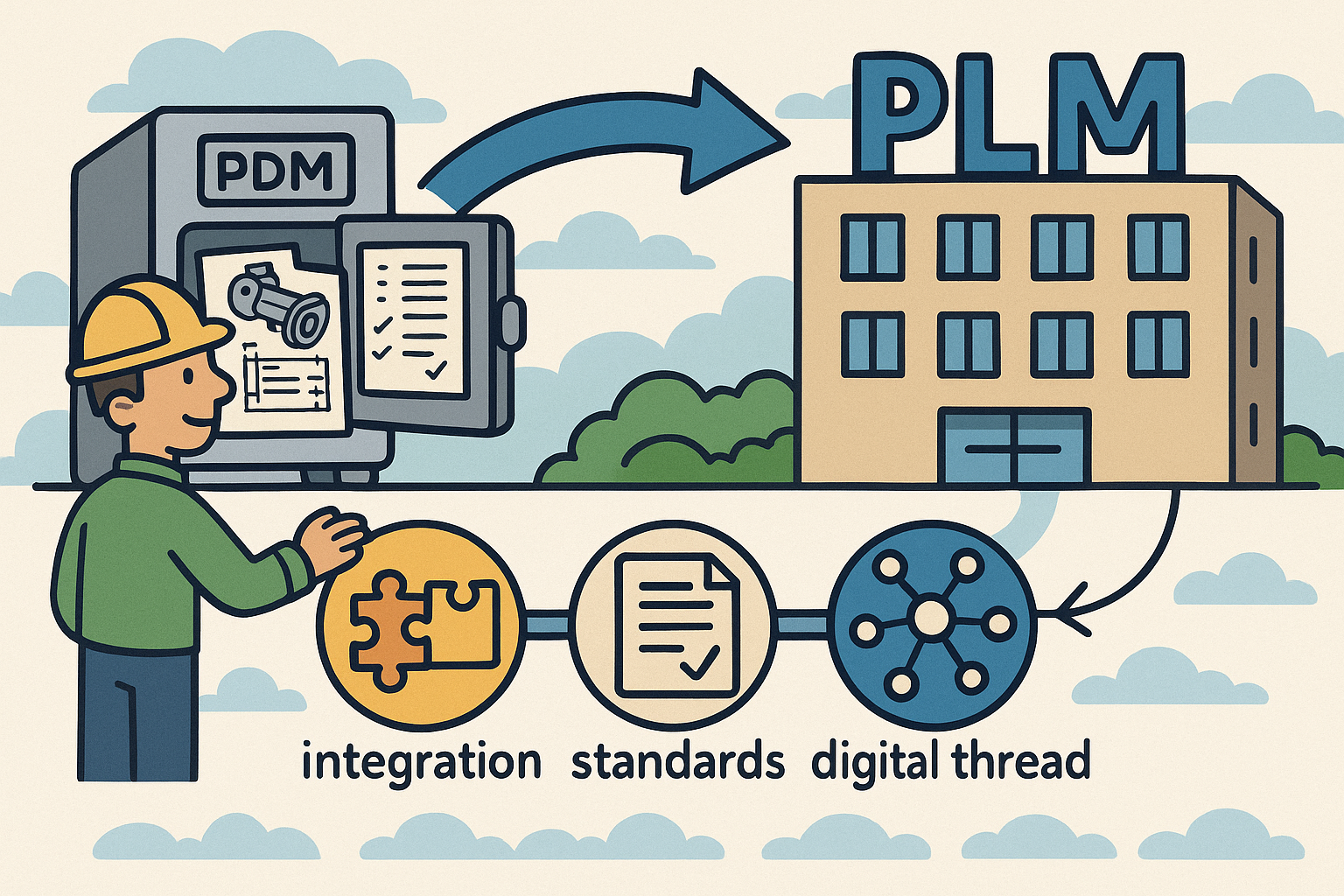
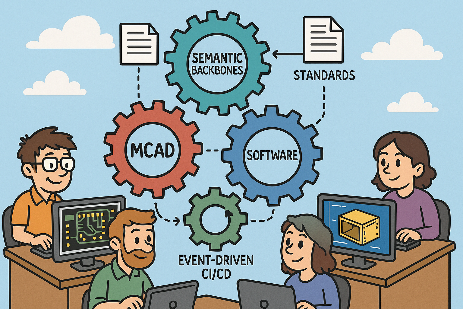
Integrated ECAD, MCAD, and Software: Semantic Backbones, Standards, and Event-Driven CI/CD


Why Integrating Electrical, Mechanical, and Software Models Matters Now
Business drivers accelerating convergence across disciplines
Smart, connected products have compressed the distance between concept and customer by collapsing hardware and software release cadence. The result is a new operating tempo where mechanical form, electronic function, and firmware behavior co-evolve in weeks, not quarters. Three forces make this convergence urgent. First, customers expect the responsiveness and feature velocity of software in physical products. OTA updates, adaptive algorithms, and subscription features push requirements churn into the late design stages, which only works if **ECAD, MCAD, and embedded code** remain traceably synchronized. Second, supply-chain volatility forces design agility: substitutions for ICs, passives, or structural materials ripple across footprints, thermal paths, tolerances, and timing. Without a cohesive thread from system intent to implementation artifacts, teams either overconstrain designs or absorb costly rework. Third, regulators demand a clean accountability trail across disciplines. Safety standards expect evidence linking hazards to requirements, design mitigations, and verified tests; **EMC/EMI** rules depend on enclosure geometry, stack-up, and return paths; cybersecurity regulations require demonstrable control over interfaces, firmware updates, and cryptographic materials. These pressures turn integration into a competitive requirement, not a luxury. The best-performing teams don’t just “share files.” They build a semantic foundation where each change—geometry feature, net rename, pin multiplex, or requirement update—creates a linked event that automates analysis and triggers targeted validation. That approach shortens feedback loops, encourages smaller, safer changes, and yields a more trustworthy product definition that stands up under audit and in the market.
- Compressed development cycles: concurrent hardware/software releases and OTA feature velocity.
- Supply-chain volatility: IC alternates, materials changes, and rapidly evolving BOMs.
- Regulatory pressure: traceable evidence across safety, EMC, and cybersecurity domains.
Pain signals from siloed workflows that surface too late
When disciplines coordinate through emails, screenshots, and sporadic handoffs, the system speaks three different languages. The first warning sign is late-stage interference. A board-level connector rotates by 90 degrees to accommodate an alternate cable, yet the enclosure boss pattern and fastener clearances remain based on the old orientation; final assembly reveals misalignment, a blocked latch, or **antenna detuning** from a slightly different ground return. Next, perfectly valid ECAD edits silently break mechanical or thermal intent. A taller package variant punctures an airflow corridor planned in MCAD; moving a heat-generating regulator from board edge to center upsets a conductive path to an internal heat spreader. Meanwhile, firmware builds on assumed pin mappings, interrupts, and power states that diverge from the evolving board constraints. The result is “it compiles, but it doesn’t boot,” brownouts under transient load, or timing drift that degrades sensor fusion. Teams try to mop up with manual checklists, but those lag reality. Each of these symptoms grows from missing links: features to requirements, nets to pins, pins to device trees, device trees to interrupts and drivers, and drivers to tests. Without explicit associations, impact analysis devolves into guesswork. The fix is to make interfaces first-class citizens with **executable contracts** tied to physical and logical identifiers. If a pin assignment changes, board definitions, calibration maps, SI/PI constraints, and **HIL smoke tests** must update automatically. If an enclosure wall moves, affected keep-outs, antenna clearances, and harness sweep paths must be flagged in minutes, not during EVT. Integration means designing the product and its conversations at the same time.
- Connector misalignment, blocked fasteners, and detuned RF from small placement edits.
- Unnoticed ECAD changes that disrupt thermal paths, standoffs, or assembly sequence.
- Firmware assumptions that miss actual I/O, timing, or power budgets, causing latent defects.
Outcomes to target and the KPIs that prove progress
Success should be unambiguous and measurable. The first leading indicator is a 30–50% reduction in **ECO turn time** driven by automated cross-domain impact analysis. The second is decreased interface-change churn, measured as **ICD diffs per sprint** and the resolution half-life of interface defects. The third is a rising requirements coverage trend that ties **MBSE** elements to tests, geometry, nets, and code; here, coverage means every requirement is allocated, implemented, and verified, and deviations are visible as deltas rather than surprises. Finally, simulate-to-test correlation must tighten: thermal predictions within a few degrees of lab data, EMC hotspots localizing to measured regions, and end-to-end latency staying within verified bounds across firmware versions. To make these outcomes operational, define what “done” looks like in data, not rhetoric. Express interface contracts in machine-readable forms; tether **SysML v2** functions to pins and features; store calibration and timing budgets alongside code; attach identifiers to parts, features, pads, and harness segments. Then wire an event-driven pipeline so each change yields derivative assets: regenerated STEP, updated EDMD/IDX, new device trees, recompiled virtual ECUs, and rerun test suites. Dashboards should surface the KPIs the same day. When a board respin takes hours to ripple through geometry, software, and verification rather than weeks, culture follows the metrics: smaller batches, sooner feedback, fewer late surprises, and higher trust in the digital product definition.
- 30–50% ECO turn-time reduction via automated impact and targeted validation.
- Lower ICD diffs per sprint and faster interface-defect resolution.
- End-to-end requirements coverage from MBSE to tests to geometry/nets/code.
- Improved simulation-to-test correlation for thermal, EMC, and latency paths.
The Interoperability Stack: Standards, Semantics, and the Digital Thread
Shared semantics and traceability that survive tool boundaries
Interoperability begins with stable meanings, not just file transfers. Assign **unique, persistent identifiers** to parts, features, nets, pins, requirements, and test cases, and store them where every tool can reference them. OSLC then acts as connective tissue that links PLM/PDM, ALM, MBSE, and test management so artifacts can reference each other without duplicating data. Requirements move via **ReqIF**, preserving identifiers, attributes, and discussions, while trace links travel across repositories as first-class citizens, not comments. At the system level, **SysML v2** provides a precise, computer-interpretable description of functions, interfaces, constraints, and allocations. Instead of prose, express the I/O of a sensor suite, timing and safety budgets, and feature variability as typed interface elements and parametric constraints that can be bound to ECAD nets, MCAD faces, and software APIs. Semantics amplify value when they are executable: interface contracts that generate checks, allocations that trigger co-simulation, and constraints that feed DRC/DFM gates. Finally, enforce a vocabulary: name nets and pins consistently, annotate units and coordinate frames, and encode variant/option rules as machine-readable logic. When a test result ties back to a requirement and to a physical pin and to a firmware driver, the digital thread holds. When identifiers break or semantics drift, the thread frays and change management reverts to tribal knowledge. Treat the semantic layer as a product: governed schemas, versioned ontologies, and backward-compatible extensions.
- OSLC links to avoid duplicating artifacts across PLM, ALM, MBSE, and test tools.
- ReqIF to exchange requirements with full fidelity and persistent IDs.
- SysML v2 as system-level source of truth for functions, interfaces, and allocations.
ECAD–MCAD exchange plus software contracts that keep interfaces live
Geometry and electronics meet through standards tailored to incremental, context-rich collaboration. **EDMD/IDX** enables board–enclosure co-design with change packages that capture component moves, keep-outs, height constraints, and mounting features. Mechanical stakeholders import just the deltas, visualize clashes, and approve or reject proposals with rationale preserved. For broader geometry, **STEP AP242** carries precise mechanical shape and PMI, while **AP210** represents electronics assemblies, including components, nets, and layout constraints. Harness data travels via KBL, PLMXML, or AP242 E3D, ensuring conductor lengths, splice placements, and connector keys remain consistent with packaging. On the manufacturing side, **IPC-2581** and ODB++ encode stack-up, impedance targets, materials, and fabrication notes—information critical to both performance and compliance. Software joins this exchange through executable interface definitions: automotive teams leverage **AUTOSAR ARXML**, while distributed products declare APIs via protobuf or OpenAPI; firmware calibration lives in **A2L** files; board definitions and device trees encode pin multiplexing mapped to pad IDs; robotics stacks describe kinematics and sensors in URDF/SDF. Tests are artifacts too: unit and integration tests should reference requirement IDs, variant options, and specific hardware configurations. When these contracts are part of the same semantic graph as geometry and nets, a single change request propagates consistently: an alternate transceiver implies different pin mux, pull-ups, device-tree entries, and driver timing, all linked to a compliance matrix for cybersecurity and EMC exposure. Interfaces stop being fragile documents and start acting like **executable guardrails**.
- EDMD/IDX for incremental board–enclosure collaboration with approvals on deltas.
- STEP AP242 for mechanical shape/PMI; AP210 for electronics; harness via KBL/PLMXML/AP242 E3D.
- IPC-2581/ODB++ with stack-up, impedance, and material semantics for manufacturing.
- Software contracts: AUTOSAR (ARXML), protobuf/OpenAPI, A2L, device trees, URDF/SDF.
Simulation, co-simulation, and a configuration-aware digital thread
High-confidence design happens when simulations mirror reality and are triggered by change, not scheduled by habit. **FMI/FMU** orchestrates plant–controller coupling, enabling virtual ECUs to run closed-loop with mechanical and electrical models. **SPICE** and **IBIS** underpin signal and power integrity analysis; **VHDL-AMS** and Verilog-A describe analog/digital behavior that bridges ECAD with system models. Thermal and CFD loops benefit from loss models extracted from ECAD (per-device power dissipation, copper density, stack-up), feeding back temperature constraints and airflow sensitivities to layout and MCAD. None of this works if configuration is fuzzy. Maintain coherent **eBOM, mBOM, and sBOM** tied to variant/option codes and effectivity dates, with feature flags flowing into firmware build systems and test selection. Change propagation rules and automated impact graphs should reveal, for a given delta, which geometries, nets, pins, calibration tables, and tests are implicated. Annotate units and coordinate frames to prevent invisible mismatches. With this backbone, a connector-pinout change launches regeneration of board definitions, device trees, and HIL smoke tests; a PDN update triggers firmware DVFS and boot-timing checks; a keep-out violation spawns clearance and airflow analyses and, if necessary, EMC hotspot visualization. The **digital thread** is not a single system—it is an agreement about identity, semantics, and responsivity across systems. When **variant logic** is encoded once and honored everywhere, simulated behavior matches the lab across options, and configuration drift becomes a solved problem rather than a recurring audit finding.
- FMI/FMU for plant–controller co-simulation and virtual ECU integration.
- Electrical behavior via SPICE/IBIS and VHDL-AMS/Verilog-A linked to system models.
- Configuration coherence across eBOM/mBOM/sBOM with variant/option rules and effectivity.
- Automated impact graphs across geometry, nets, pins, and code enforce the digital thread.
Implementation Blueprint: Architectures, Automation Patterns, and Pitfalls
Reference integration architecture and schema mediation
Establish a configuration backbone first: PLM/PDM becomes the steward of part numbers, assemblies, change workflows, and effectivity. ALM hosts work items, code, pipelines, and test evidence; MBSE repositories hold **SysML v2** models as the formal articulation of system logic, interfaces, and allocations. Connect them using an event-driven integration bus. Webhooks plus OSLC/REST endpoints allow near-real-time synchronization, where an ECAD commit becomes an event that pushes a targeted delta into MCAD reviews, rather than a manual file drop. At the center sits a schema mediation service that translates **EDMD/IDX, STEP, ARXML, and ReqIF** into a shared entity graph indexed by stable identifiers. It enforces units, coordinate frames, and variant logic, and exposes a query API—“show all artifacts impacted by net NET_CAM_MIPI across variants X and Y”—so downstream tools and dashboards can present precise to-do lists. For traceability, store links at the entity level (net, pin, face, requirement, test) rather than the file level. That design keeps large models modular and allows granular diffs and targeted rebuilds. Treat test benches and simulations as first-class products within this architecture: register FMUs, SPICE decks, CFD templates, and HIL rigs with the same identifiers and effectivity rules that govern hardware. Lastly, adopt export-first policies and microservice adapters rather than hard-coding to vendor APIs, ensuring that **tool lock-in** never becomes the architecture’s limiting factor. The goal isn’t one tool to rule them all; it is a thin and **semantic backbone** that turns repositories into cooperating peers.
- PLM/PDM for configuration and change; ALM for code and tests; MBSE for system logic.
- Event-driven bus with webhooks + OSLC/REST for near-real-time sync.
- Schema mediation that builds a shared, identifier-rich entity graph across domains.
Cross-domain CI/CD: triggers and pipelines that touch atoms and bits
Continuous integration is the antidote to integration surprises. Start by codifying triggers that reflect real-world couplings. An **ECAD footprint/placement change** should automatically regenerate a STEP facsimile of the board, run clearance checks against fasteners and walls, analyze airflow deltas around heatsinks, and publish a photoreal and **EMC hotspot** visualization. A **PDN update** must dispatch firmware pipelines for DVFS profiles, boot timing, and brownout resilience, while recalculating PI margins. A **connector/pinout change** regenerates board definitions and device trees, recompiles drivers, and executes **HIL smoke tests** with loopbacks and boundary scans. Treat pipelines as composable stages that fan out and converge. For geometry: DRC/DFM gates followed by step-file regeneration, clearance/fastener/assembly checks, and rendering. For electronics: netlist and impedance diffs feed SI/PI simulations, with results informing timing regressions in software-in-the-loop. Each pipeline publishes evidence: reports tied to requirement IDs and variant flags, with artifacts signed and effectivity-tagged for audits. Crucially, failures should localize to entities (“pad U7.23 violates keep-out K100”) and propose fixes (rotate 90°, move 0.8 mm) rather than dumping thousand-line logs. Over time, you can enrich triggers: thermal excursions reopen layout options, antenna proximity suggests revised keep-outs, harness bend radii prompt spline edits. This is **event-driven CI/CD** for physical and digital artifacts, turning changes into predictable, low-drama routines rather than cross-team firefights.
- Triggers: ECAD placement → clearance + airflow + visualization; PDN update → firmware timing + PI; pinout change → device-tree regen + HIL.
- Pipelines: DRC/DFM → STEP regen → clearance/assembly checks → photoreal/EMC viz.
- Electronics: Netlist/impedance diffs → SI/PI → timing regressions in SIL/virtual ECU.
Collaboration practices, governance, and pitfalls with pragmatic mitigations
Well-chosen tools fail without disciplined practices. Anchor discussions to entities—nets, faces, features, requirements—so markups persist in PLM/ALM with identity, variant, and effectivity intact. Use mixed-reality sessions for spatially complex issues like harness routing and antenna keep-outs, synchronized to the same identifiers so decisions become searchable artifacts, not meeting folklore. Treat **Interface Control Documents** like code: versioned, diffable, with approvals and automated checks enforcing schema and naming hygiene. Governance should scale with automation: a cross-discipline CCB receives auto-generated impact summaries and maintains audit-ready trace matrices. Map safety and security standards—ISO 26262, IEC 60601, DO-178C/DO-254, IEC 62443—to explicit artifacts and tests; the compliance story is then a query, not a scramble. Common pitfalls are predictable. Units and coordinate mismatches bleed into silent errors; enforce schemas with units metadata, reference frames, and converter tests. Variant explosion buries teams; adopt feature/option models and rule-based configuration so product variability is encoded once and evaluated everywhere. Partial standard implementations sabotage trust; institute contract tests against vendor translators, keep **golden reference models**, and budget time for round-trip validation. Tool lock-in creeps when integrations hard-code proprietary formats; prefer open standards and **microservice adapters**, and maintain export-first patterns to keep exits viable. Above all, don’t conflate data lakes with digital threads. A thread needs identity, links, and behavior. With those basics, even imperfect tools cooperate; without them, even the best tools become silos with nicer UIs.
- Entity-anchored markups persisted in PLM/ALM for durable, searchable reviews.
- Mixed-reality sessions for spatial problems like harnesses and antenna keep-outs.
- Compliance mapped from standards to artifacts/tests for audit-ready evidence.
- Pitfalls and mitigations:
- Units/frames mismatches → strict schemas with units and coordinate metadata.
- Variant explosion → feature/option modeling and rule-based configuration.
- Partial standards → contract tests, translator verification, golden models.
- Tool lock-in → open standards, adapters, export-first policies.
Conclusion
From handoffs to a synchronized loop that lifts quality and speed
Integrated design across ECAD, MCAD, and software turns a brittle handoff chain into a synchronized loop where each change elicits immediate, cross-domain validation. The prize is fewer late surprises, leaner ECO cycles, and more confident releases. The winning formula combines a **semantic backbone**—SysML/OSLC/ReqIF providing stable identity and trace links—with robust geometry/electronics exchange—**EDMD/IDX, STEP, AP210**—and **executable interface contracts** that bind firmware and APIs to real pins and shapes. Around this core, build **event-driven CI/CD** that treats models, code, and tests as peers. When a connector rotates, board definitions regenerate, HIL tests run, airflow and EMC checks refresh, and stakeholders resolve impacts with entity-level clarity. When a component substitute lands, impedance updates kick off SI/PI and timing regressions; thermal models ingest power shifts and feed constraints back to layout. With configuration managed across eBOM/mBOM/sBOM and variant logic shared, lab measurements reconcile with simulations because you are validating the same product definition, not a cousin. The transformation is not about one vendor stack; it is about insisting that every artifact carries identity, semantics, and context so automation can reason and act. Speed follows structure: smaller changes, faster checks, cleaner integrations, and the confidence to push features without secretly betting the schedule. Integration is not a phase; it is a property of the system you are building, and it either compounds value or compounds risk.
- Semantic backbone: SysML/OSLC/ReqIF for identity and traceability.
- Robust exchanges: EDMD/IDX, STEP, AP210 for geometry and electronics.
- Executable contracts for interfaces that drive automated checks and code generation.
- Event-driven CI/CD spanning physical and digital artifacts.
Start small, automate impact, measure relentlessly, and let culture follow
Big-bang transformations stall; precision strikes compound. Pick a high-friction interface—often the **connector/pinout to firmware device trees**—and wire it front-to-back. Assign stable IDs to pads and pins, define the interface contract in ARXML or an IDL, auto-generate board definitions and device trees, compile drivers, and run HIL smoke tests on every change. Add EDMD/IDX deltas to drive enclosure clearance checks around the same connector, and publish photoreal plus EMC heatmaps to make spatial impacts obvious. In parallel, stand up a **schema mediation** service so your links are durable. Then iterate: bring PDN into the loop with DVFS and PI checks; fold in thermal with ECAD loss models; introduce FMI/FMU co-sim where controller logic benefits from plant feedback. Measure as you grow. Track ECO turn time from proposal to validated approval. Watch **ICD diffs per sprint** trend downward while resolution half-life shrinks. Report **requirements coverage** from MBSE to tests to geometry/nets/code, and post **simulation-to-test correlation** deltas after each build. Share these metrics openly; they become the story that changes minds. As friction drops, teams naturally split changes into smaller, verifiable steps, and reviews shift from file politics to entity-level reasoning. Integration at this level does not just prevent rework; it accelerates learning. With faster feedback, you explore more options, make better tradeoffs, and ship with fewer compromises. That is how integration stops being an initiative and becomes a competitive habit.
- Start with a contained, high-friction interface and make it **executable**.
- Automate impact analysis and targeted validation before scaling breadth.
- Instrument KPIs—ECO time, interface-change churn, coverage, and correlation—and publish them.
- Let visible wins reshape culture; small loops, fast learning, durable quality.
Also in Design News