Your Cart is Empty


Generative Workflows Are Rebuilding Mechanical Concept Development


Why Mechanical Concept Development Is Being Rebuilt Around Generative Workflows
The old sequence is reaching its practical limit
Mechanical concept development has traditionally been shaped by the speed and experience of the engineer sitting in front of the CAD system. A designer begins with a known architecture, sketches a promising form, builds a parametric model, applies approximate dimensions, and then waits until enough geometry exists to run meaningful simulation. This process can produce excellent products, but it also encourages a narrow search pattern because every serious alternative requires manual remodeling. When a mounting interface changes, a clearance envelope shifts, or a new load direction appears, the concept often needs to be rebuilt rather than simply reevaluated. The result is a development culture where early decisions become artificially expensive to question. Experienced engineers learn to avoid risky forms because they know the downstream cost of rebuilding them. In that environment, innovation is frequently filtered through what can be modeled quickly, not necessarily what performs best. Generative workflows challenge this sequence by moving engineering intent ahead of geometry creation, allowing software to explore feasible configurations before the team commits to a single mechanical architecture.
Design intent becomes a computational asset
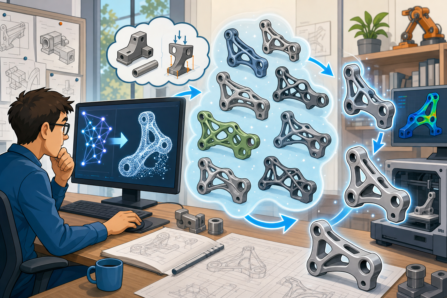
The most important change introduced by generative design is not that software can create organic-looking shapes. The deeper shift is that design intent becomes computational. Instead of beginning with a manually modeled bracket, housing, linkage, or support arm, the engineer defines what the component must accomplish. The system receives keep-in zones, keep-out regions, load cases, stiffness targets, mass limits, material options, manufacturing rules, and interface constraints. These inputs describe the design problem in a form that can be searched, tested, and compared. In a conventional workflow, design intent may live in an engineer’s notes, a requirements document, or the implicit logic of a CAD model. In a generative workflow, that same intent becomes an executable model of the design space. This matters because the early concept stage is where the cost of change is lowest and the influence on product performance is highest. By translating requirements into computational boundaries, engineering teams can investigate more possibilities before the first detailed feature tree is created.
- Performance targets define stiffness, strength, thermal behavior, displacement limits, and vibration response.
- Manufacturing constraints define whether the geometry must be machinable, castable, printable, or assembled from multiple parts.
- Assembly interfaces define fixed mounting surfaces, bolt locations, bearing seats, cable clearances, and inspection access.
- Business constraints define weight, cost, material availability, serviceability, and production volume assumptions.
From single concepts to navigable design spaces
In a manually driven concept process, the team often compares a small number of alternatives: the conservative version, the lightweight version, the compact version, and perhaps one unconventional proposal. Generative design expands this comparison by producing families of solutions that reflect different priorities. One candidate may minimize mass while accepting higher machining complexity. Another may preserve stiffness with a more conventional geometry. A third may suggest an additive manufacturing direction that consolidates several parts into one. The engineer is no longer asking, “Can I model a better version of this idea?” The question becomes, “Which region of the design space produces the most useful trade-off?” This is a profound change because mechanical design is rarely a single-objective problem. A component must survive loads, fit in an assembly, meet cost targets, remain inspectable, and support the manufacturing strategy. Structured design space exploration makes those trade-offs visible much earlier, allowing expert judgment to operate on richer evidence rather than a limited set of manually modeled options.
Building a Practical Generative Design Workflow
Starting with simplified geometry and intentional boundaries
A practical generative design workflow begins with restraint. The best inputs are usually not fully detailed CAD assemblies with every fillet, thread, groove, and cosmetic surface included. Instead, the engineer should prepare a simplified representation that captures the functional truth of the problem. Keep-in zones define where material may exist, while keep-out zones protect adjacent components, maintenance access, airflow passages, tool paths, and human interaction areas. Mounting points, bearing bores, bonded surfaces, sealing faces, and datum structures must be modeled carefully because these are not decorative details; they are the fixed commitments around which the generated design must function. Load paths should be represented with realistic directions, magnitudes, and contact assumptions. If the input exaggerates stiffness at a support or ignores a secondary load case, the software may produce an elegant geometry that performs well only inside a flawed abstraction. Generative design quality depends directly on problem definition quality, so the early setup deserves the same discipline normally reserved for detailed validation.
- Define non-negotiable geometry such as bolt bosses, shaft centers, sealing surfaces, and assembly datums.
- Protect neighboring components with keep-out volumes rather than relying on visual judgment after generation.
- Represent the real load environment, including off-axis forces, torque reactions, shock loads, and service handling loads.
- Remove unnecessary cosmetic detail so the solver explores function rather than inherited modeling clutter.
Configuring materials, processes, and exploration criteria
Once the functional regions are defined, the next decision is how many assumptions should be opened for exploration. Material selection is not merely a final procurement decision; it changes stiffness, mass, fatigue behavior, heat transfer, corrosion resistance, machinability, and cost. A generative setup may compare aluminum alloys, titanium, stainless steel, engineering polymers, or composite-compatible inserts, but the comparison is only meaningful if the downstream manufacturing strategy is also defined. A CNC-machined part must respect tool access, minimum internal radii, stock orientation, and fixturing assumptions. A cast component must consider draft, wall thickness, feeding, shrinkage, and post-machined interfaces. An additively manufactured component may exploit lattice structures and internal passages, but it must still address support removal, surface finish, powder evacuation, heat distortion, and qualification requirements. The engineer should also define how candidates will be ranked. Mass alone is rarely sufficient. A useful comparison may include safety factor, displacement, natural frequency, cost proxy, build orientation, support volume, and manufacturing confidence. This turns generation from a visual novelty into an engineering decision process.
- Use material options to expose trade-offs between weight, stiffness, cost, fatigue life, and thermal behavior.
- Apply process-specific rules early so the generated concepts are closer to manufacturable geometry.
- Rank candidates with several metrics, not only mass reduction or visual complexity.
- Preserve rejected alternatives when they reveal useful load paths or architectural ideas.
Evaluating families of generated alternatives
The evaluation stage is where generative design becomes strategically valuable. A large outcome set should not be treated as a gallery of strange shapes, but as a structured map of competing engineering decisions. Designers should group candidates by their dominant characteristics: shortest load path, lowest mass, highest stiffness, simplest manufacturing route, best packaging compatibility, or easiest post-processing. Visual comparison is useful because the human eye quickly recognizes whether a candidate respects assembly logic, tool access, and intuitive force flow. Quantitative filtering is equally important because visually convincing geometry may still fail displacement, buckling, fatigue, or frequency requirements. The strongest teams combine both methods: they use plots and scorecards to narrow the field, then inspect the geometry for assumptions the metrics cannot fully understand. A generated solution that looks inferior may contain an unexpected rib direction or tied arch structure worth adapting into a more conventional concept. The goal is not to accept the first generated result, but to learn what the design space is trying to reveal.
Connecting generation to CAD, simulation, and manufacturing preparation
A generative workflow only becomes production-relevant when it connects to downstream processes. Generated geometry often begins as mesh-like or boundary-representation output that may not be easily edited in a traditional parametric CAD environment. Engineers must decide whether to reconstruct the shape as clean parametric geometry, preserve it as a manufacturing mesh, or use hybrid modeling tools that combine direct editing, subdivision surfaces, and feature-based control. After reconstruction, the part should be validated with independent simulation rather than relying entirely on the assumptions of the generative solver. Structural, thermal, vibration, fatigue, and contact behavior may need more detailed review, especially where the generated concept includes thin members, stress concentrations, or unusual transitions. Manufacturing preparation then translates the concept into toolpaths, build orientations, support strategies, inspection plans, and tolerance schemes. PLM or PDM integration is also essential because generative exploration can create many versions quickly. Without disciplined traceability, teams may lose track of which loads, materials, solver settings, and manufacturing rules produced a specific candidate.
- Use CAD reconstruction when the geometry must remain editable through future product changes.
- Run independent simulation validation with refined contacts, mesh controls, fatigue checks, and thermal conditions where needed.
- Prepare CAM or additive manufacturing data early enough to identify tool access, support, and inspection issues.
- Store generated variants with metadata so design decisions remain traceable across the development program.
Where Generative Design Accelerates Mechanical Engineering
Lightweight structures and early load-path discovery
The clearest advantage of generative design appears in components where mass, stiffness, and packaging constraints compete strongly. Brackets, support arms, actuator mounts, chassis nodes, robotic end effectors, and aerospace or automotive structural connectors often contain material that exists because of historical modeling habits rather than current load requirements. Generative tools are effective at identifying direct load paths that may be difficult for a designer to see when beginning from a rectangular block, plate, or legacy casting. The software can remove low-value material while preserving structural continuity between functional interfaces. This does not mean that every generated part is automatically superior, but it can expose the mechanical logic hidden inside the boundary conditions. Engineers can study where material repeatedly appears across many candidates and where it disappears without performance penalty. Those patterns provide insight even if the final product is modeled manually. Earlier load-path discovery compresses the concept phase because the team can evaluate structural behavior before investing in detailed CAD features that may later need to be reversed.
Applications that benefit from geometric freedom
Generative design becomes especially powerful when geometry is not severely limited by traditional subtractive manufacturing. Additive manufacturing is the obvious example because it can produce internal channels, lattice transitions, complex branching members, and consolidated assemblies that would be impossible or uneconomical to machine from a solid billet. However, generative thinking is not limited to 3D printing. A casting-aware workflow can produce ribbed, tapered, and hollowed forms suitable for foundry processes. A machining-aware workflow can restrict the solution to accessible surfaces, defined tool directions, and practical removal volumes. In robotics, generative design can reduce end-effector mass, which improves acceleration, cycle time, payload efficiency, and motor sizing. In medical devices and custom implants, geometry can be adapted to patient-specific anatomy while maintaining porous surfaces or stiffness profiles that support biological and mechanical requirements. Aerospace and motorsport applications benefit from grams saved across many components. The unifying theme is that geometric freedom has engineering value only when the manufacturing process can actually deliver it reliably.
- Structural brackets can be optimized around bolt patterns, reaction loads, and packaging constraints.
- Robotic end effectors can be lightened to improve speed, accuracy, and actuator efficiency.
- Custom medical components can combine anatomical fit with controlled stiffness and porous surface regions.
- Additive manufacturing parts can consolidate assemblies and remove fasteners, interfaces, and alignment operations.
Reducing dependence on inherited assumptions
Many mechanical designs begin as modifications of previous products. This is efficient, but it also carries forward assumptions that may no longer be valid. A rib location may exist because an earlier casting needed it, not because the new load path requires it. A thick boss may remain from a previous fastener standard. A housing may preserve machining allowances that no longer apply to the selected production method. Generative exploration provides a way to challenge these inherited choices without immediately abandoning engineering discipline. By defining current requirements and allowing the software to search without the full geometry of the legacy part, teams can see whether familiar forms are genuinely justified. This is particularly valuable when a product shifts material, manufacturing volume, or duty cycle. The generated alternatives may validate the old architecture, but they may also reveal that stiffness can be achieved through a different arrangement of material, that two parts can be merged, or that an assembly interface is unnecessarily restrictive. In this sense, generative design is a tool for design assumption auditing as much as optimization.
Where Generative Design Still Struggles
Constraint definition remains the critical failure point
Generative systems are extremely sensitive to the assumptions they receive. If the boundary conditions are wrong, the outputs can be impressively precise and fundamentally misleading. A fixed support that is modeled as perfectly rigid may produce a design that transfers force into a surrounding structure incapable of carrying it. A load case that omits torsion, fatigue, thermal expansion, assembly preload, or accidental misuse may generate a lightweight shape that passes the defined study while failing the real product environment. Manufacturing constraints can also be underdefined. For example, a part may be labeled as machinable, but the setup may not represent actual tool length, fixturing strategy, tolerance stack-up, or access for deburring and inspection. This is why expert engineering judgment remains central. Generative design can explore an enormous number of possibilities inside a defined problem, but it does not automatically know whether the problem is complete. Poorly defined constraints produce poor design intelligence, even when the resulting geometry looks sophisticated and simulation reports appear favorable.
Generated geometry can resist practical editing
Another persistent limitation is the gap between generated form and editable product definition. Many generative outputs include smooth, branching, organic transitions that perform well numerically but are difficult to capture in feature-based CAD. A designer may need to turn a complex mesh into manufacturable geometry with controlled radii, standardized wall thickness, accessible surfaces, tolerance-ready datums, and inspection features. This reconstruction step can reduce or alter the original performance advantage if it is handled casually. Direct modeling, subdivision tools, implicit modeling, and hybrid parametric workflows are improving this transition, but they do not remove the need for careful interpretation. Engineers must decide which features express essential load paths and which are solver artifacts. They must also create geometry that future teams can modify when requirements change. A beautiful optimized form that cannot be edited, dimensioned, inspected, or explained may become a lifecycle liability. For production engineering, editable design intelligence is often more valuable than a mathematically perfect shape frozen in an inconvenient format.
Manufacturing, service, and cost are broader than optimization metrics
Generative design studies frequently focus on structural performance, mass reduction, and manufacturability rules, but real products must survive a wider set of constraints. A component may need to be cleaned, coated, serialized, inspected, repaired, replaced, or assembled by a technician wearing gloves. It may require wrench access, visual alignment cues, drainage paths, protective covers, or standardized fasteners. These requirements are not always easy to encode in a solver. Cost is equally complex. A generated part that reduces mass may increase machine time, inspection complexity, heat treatment distortion, support removal effort, or supplier risk. Additive manufacturing may allow exceptional geometry, but build orientation, nesting efficiency, powder handling, surface finishing, qualification, and post-machining can dominate the business equation. Sustainable design adds another layer because material efficiency during use must be weighed against energy-intensive production, recyclability, and repairability. These realities do not weaken the value of generative design; they define where it must be integrated with broader engineering methods. The best workflow treats generated results as high-quality proposals that still require manufacturing, service, and cost intelligence.
- Assembly requirements may include tool clearance, alignment features, ergonomic handling, and fastening sequence logic.
- Inspection requirements may demand accessible datum surfaces, probe paths, section thickness limits, and nondestructive testing access.
- Service requirements may include replacement clearance, cleaning access, wear allowances, and part identification surfaces.
- Cost requirements may include machine time, supplier capability, finishing operations, scrap rates, and qualification burden.
From Faster Concepts to Smarter Engineering Decisions
Generative design as an engineering collaborator
The most successful use of generative design is not based on the idea that software should replace mechanical reasoning. Instead, the software acts as an intelligent collaborator that expands the range of visible options. Engineers still define the problem, challenge the assumptions, evaluate the results, and decide which trade-offs are acceptable. This partnership is powerful because humans and algorithms are strong in different areas. Engineers understand product context, failure modes, manufacturing nuance, customer expectations, and organizational constraints. Generative systems are strong at repeated computation, geometric variation, and exposing load-path patterns that may not emerge from familiar modeling habits. When these strengths are combined, concept development becomes both faster and more rigorous. The designer does not lose authority; the designer gains a more informed field of choices. The winning workflow is decision-centered: define constraints, generate concepts, rank alternatives, refine geometry, validate behavior, and prepare for manufacturing. Speed matters, but the more valuable outcome is better judgment earlier in the design cycle.
Integrating the broader digital thread
Generative design reaches its full potential when it is part of a broader digital workflow rather than an isolated experiment. Parametric CAD provides design control and downstream editability. Simulation-driven validation confirms structural, thermal, vibration, fatigue, and multiphysics behavior with greater fidelity. CAM and additive manufacturing preparation translate geometry into process-ready instructions. PLM and PDM systems preserve version control, requirements linkage, approval status, and traceability. Cost analysis connects geometry choices to procurement and production realities, while sustainability analysis examines material use, energy consumption, lifecycle service, and end-of-life implications. This connected environment allows a generated concept to mature without losing the reasoning that created it. It also helps teams compare alternatives across multiple dimensions instead of optimizing one metric in isolation. A very lightweight part may not be the best choice if it raises cost, inspection burden, or carbon impact disproportionately. The future of advanced mechanical concept development will depend on how well software connects performance optimization with the full digital thread of engineering responsibility.
- Parametric CAD keeps geometry adaptable as interfaces, dimensions, and requirements evolve.
- Simulation validation ensures that generated concepts survive more detailed and realistic engineering checks.
- Manufacturing feedback prevents elegant shapes from becoming impractical production problems.
- Data management protects traceability across many generated variants and decision points.
- Cost and sustainability analysis broaden optimization beyond weight and stiffness alone.
The future is computational exploration guided by expert judgment
Generative design is rebuilding mechanical concept development because it changes when and how engineers learn about a design problem. Instead of waiting for late-stage simulation to reveal weaknesses in a nearly committed CAD model, teams can explore performance, manufacturability, and trade-offs at the beginning. The technology’s real value is not simply faster geometry creation; it is the ability to reveal alternatives that may never appear through conventional modeling. Yet the future will not belong to workflows where software designs products alone. It will belong to teams that develop disciplined methods for defining constraints, interpreting outputs, reconstructing geometry, validating behavior, and connecting results to manufacturing and lifecycle decisions. As generative tools become more capable, the competitive advantage will shift from having access to the software to knowing how to ask better engineering questions. The most advanced teams will use computation to expand imagination, reduce assumption-driven repetition, and make smarter decisions while the design is still flexible. That is where generative design becomes more than automation: it becomes a practical framework for engineering intelligence at the concept stage.
Also in Design News