Your Cart is Empty


Design Software History: From 2D Drafting to BIM: The Evolution of Architectural Documentation
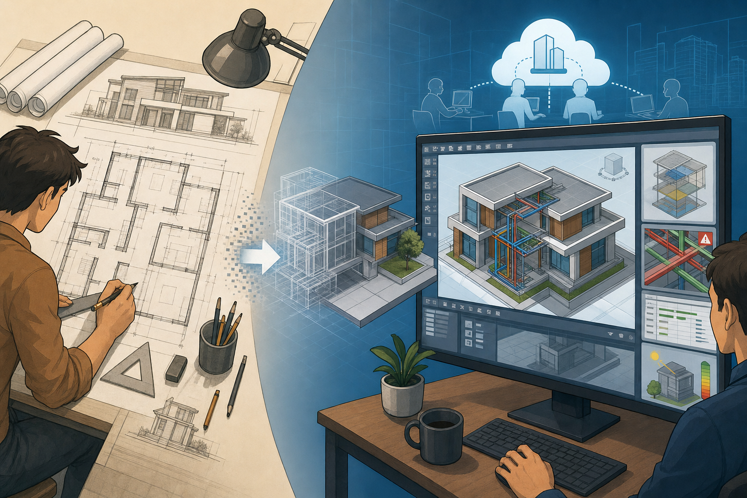


From the Drafting Board to the Digital Sheet
The persistence of the drawing as the construction language
For most of modern architectural history, the building was communicated through a disciplined set of 2D construction documents: plans, sections, elevations, schedules, enlarged details, reflected ceiling plans, structural framing drawings, mechanical layouts, electrical diagrams, and written specifications. This was not an accidental convention. Drawings became the legal, contractual, and practical language through which owners, architects, engineers, contractors, fabricators, inspectors, and authorities having jurisdiction could agree on what was to be built. A plan explained spatial organization and dimensions; a section revealed vertical relationships; an elevation clarified exterior composition; a schedule organized doors, windows, finishes, hardware, and equipment; and a detail sheet translated design intent into constructible assemblies. The entire construction industry learned to read buildings through these slices and symbolic abstractions. Long before computers entered architectural offices, manual drafting created a shared professional grammar based on line weights, hatching, lettering, reference bubbles, dimensions, grids, and drawing scales. That grammar was reinforced by architectural education, engineering standards, municipal review processes, and construction contracts. In practice, the drawing set was not merely a visual record of the design; it was the authoritative instrument through which responsibility, coordination, scope, and risk were distributed among the many parties involved in building production.
Why 2D Plans Dominated Architectural Practice for So Long
Manual drafting created a durable professional culture
Two-dimensional documentation lasted because it was efficient within the constraints of paper, print reproduction, professional liability, and jobsite communication. Architects and engineers could not send a physical building to a contractor, so they reduced the building to coordinated views that could be printed, marked up, archived, and issued. Drafting boards, T-squares, parallel rules, lead holders, ink pens, Mylar sheets, vellum, pin bars, and blueprint reproduction systems formed a mature production ecosystem. Large offices developed elaborate drafting-room hierarchies in which principals, project architects, job captains, draftspeople, specification writers, and consultants each contributed to the production of the final set. The medium encouraged repetition because every view had to be drawn as a separate artifact. If a stair changed, the plan, section, detail, handrail elevation, room finish schedule, and sometimes structural drawings all had to be revised by hand. Yet the system survived because everyone understood its conventions. Builders could measure from drawings, estimators could take off quantities, reviewers could stamp permit sets, and lawyers could interpret contractual obligations. The drawing was both a design representation and a legal technology, which explains why it remained dominant even after computers began appearing in architectural practice.
The First Architectural CAD Wave
Digitizing the drafting table rather than reinventing documentation
The first broad wave of architectural CAD did not immediately transform architecture into model-based practice. Instead, it made the drafting table electronic. Systems such as AutoCAD from Autodesk, VersaCAD from VersaCAD Corporation, MicroStation from Bentley Systems, DataCAD from DATACAD LLC, and MiniCAD, later renamed Vectorworks, gave architects faster tools for drawing lines, arcs, polylines, dimensions, hatch patterns, symbols, and text. AutoCAD, introduced in 1982 under the leadership of John Walker and the early Autodesk team, became especially influential because it ran on relatively affordable personal computers rather than only on expensive minicomputers or workstations. MicroStation evolved from Intergraph-related technology and became a major platform in engineering, transportation, infrastructure, and large architectural organizations. These tools improved production speed, legibility, plotting consistency, and revision management, but they largely preserved the logic of the paper drawing. A wall was still commonly represented by two parallel lines. A door was a block or symbol inserted into a plan. A window tag was text or an attributed block. A schedule might be drafted manually or stored separately in a spreadsheet. Early CAD made construction drawings cleaner and more editable, but the underlying workflow remained sheet-centered, view-specific, and heavily dependent on office discipline.
What Early CAD Improved and What It Could Not Solve
Higher speed, cleaner output, persistent coordination problems
The practical benefits of 2D CAD were substantial. A firm could copy typical details, stretch geometry, mirror room layouts, reuse standard blocks, plot at multiple scales, and manage complex linework with layers. Revision clouds, title blocks, xrefs, symbol libraries, and pen tables improved production control. Office standards emerged around layer naming, color-to-lineweight plotting, block insertion points, text styles, and file reference structures. However, the approach created a new form of digital fragility. Because information was repeated across many independent drawings, inconsistency remained common. A door might be moved in plan but remain in the wrong location in an elevation. A slab depth changed in section might not be reflected in a detail. A room number changed in one drawing might not update in a finish schedule. Even when external references helped teams share backgrounds, the information was still not truly unified as building knowledge. The computer had replaced ink with vectors, but it had not given the wall, door, room, or floor slab an integrated identity. Early CAD accelerated documentation without eliminating the coordination burden. The office still relied on experienced staff, redline reviews, drawing checklists, plotting routines, and conventions that varied from firm to firm.
- Duplicated information appeared across plans, elevations, sections, details, and schedules.
- Layers, blocks, and symbols required strict standards to avoid confusion.
- Design changes still triggered manual checking across multiple drawings.
- CAD files documented geometry but usually did not understand building meaning.
The Emergence of the Building Model
From graphic entities to building descriptions
The intellectual shift toward model-based architectural documentation began when researchers and software developers asked a simple but radical question: why should a wall be only two lines? In a more intelligent system, a wall could have height, thickness, material layers, fire rating, acoustic properties, structural function, cost data, thermal behavior, and relationships to floors, roofs, doors, windows, and rooms. This idea drew from decades of research into building product models, computer-aided design databases, and semantic descriptions of buildings. Charles Eastman, a central figure in this history, wrote influential work on building descriptions and product modeling while teaching and conducting research at institutions including Carnegie Mellon University and Georgia Institute of Technology. His 1970s vision of a “building description system” anticipated many principles later associated with BIM: objects, attributes, relationships, and the generation of drawings from a coordinated model. Eastman and other researchers recognized that the computer did not need to imitate paper directly. It could store a building as structured information and derive drawings from that information. This was a profound change because it moved the center of architectural computing from representation to computation, from visible linework to an underlying database-like description of constructed reality.
Research Roots of Building Product Models
Databases, geometry, and the early theory of architectural objects
During the 1970s and 1980s, architectural computing researchers explored how buildings could be represented as combinations of geometry, attributes, and relationships. This work was influenced by developments in solid modeling, computer graphics, relational databases, object-oriented programming, and engineering product data management. In mechanical CAD, companies and systems such as Computervision, Applicon, SDRC, CATIA from Dassault Systèmes, and later PTC’s Pro/ENGINEER demonstrated that digital models could carry more than drawn views. In architecture, the challenge was different because buildings involve many systems, uncertain changes, regulatory constraints, and multiple organizations working simultaneously. Still, the theoretical direction was clear: a building model could support drawings, analysis, quantity extraction, code checking, energy simulation, and facility management if its objects were defined consistently. Charles Eastman’s work, along with contributions from researchers involved in integrated building models and product data standards, helped establish the basis for later industry initiatives. The development of STEP standards and later IFC, led through buildingSMART International and its predecessors, reflected the same desire to exchange meaningful building information rather than disconnected lines. The core historical idea was that architecture needed computable building knowledge, not simply faster drafting.
Commercial Object-Based Architectural Tools Appear
Archicad, MicroStation-based architecture, and the object turn
One of the earliest commercially successful systems to embody building-model thinking was Archicad, developed by the Hungarian company Graphisoft under the leadership of Gábor Bojár. Released in the 1980s for the Apple Macintosh, Archicad presented what Graphisoft called a “Virtual Building,” an approach in which architects created walls, slabs, roofs, doors, windows, stairs, and other architectural elements rather than merely drawing lines. This was historically significant because Archicad brought object-based building modeling into professional practice before BIM became an industry slogan. Bentley Systems also advanced model-oriented workflows through MicroStation and later Bentley Architecture, especially in large infrastructure and multidisciplinary environments where reference coordination and robust file handling were essential. Autodesk, whose AutoCAD dominated 2D drafting, introduced Autodesk Architectural Desktop in the late 1990s as a transitional product that added walls, doors, windows, spaces, and object-based documentation on top of AutoCAD. Architectural Desktop was important because it acknowledged the limitations of pure drafting while still serving offices invested in DWG-based workflows. It showed the industry’s intermediate condition: firms wanted intelligent building objects, but they also needed compatibility with existing detail libraries, consultant files, plotting standards, and established production habits.
Revit and the Parametric Building Model
A turning point in associative documentation
Revit marked a decisive moment because it treated the building model as a coordinated parametric database from the beginning. The software was created by Charles River Software, founded in 1997 by Leonid Raiz and Irwin Jungreis, both of whom had experience with PTC’s Pro/ENGINEER and understood the power of parametric modeling. The company was later renamed Revit Technology Corporation, and Autodesk acquired it in 2002. Unlike AutoCAD-based workflows, Revit was organized around the principle that a change anywhere should be a change everywhere. A wall moved in plan could update sections, elevations, schedules, dimensions, and dependent views. A door family could include geometry, symbolic representation, parameters, materials, fire rating, hardware properties, and schedule data. Views were not isolated drawings but associative windows into the same model. Families, components, constraints, levels, grids, hosted objects, view templates, schedules, tags, and annotation systems formed an interconnected documentation environment. The Revit model changed the mental unit of work from drafting entities to parametric building elements. This did not make architectural judgment automatic, nor did it eliminate detailing, but it placed coordination at the center of the software architecture instead of treating it as an afterthought.
- Parametric objects allowed changes in size, type, material, and relationships to propagate through the model.
- Associative views connected plans, sections, elevations, 3D views, and details to shared model information.
- Families and components gave offices reusable systems for doors, windows, furniture, equipment, annotations, and assemblies.
- Automated schedules extracted quantities and properties from modeled elements rather than relying only on manual tabulation.
The Mental Shift from Drawing Views to Constructing a Digital Building
Documentation became a consequence of modeling decisions
The emergence of BIM required architects to think differently about production. In a 2D CAD workflow, the drafter composed each view as an independent drawing. In a model-based workflow, the team constructs a coordinated digital building and then configures plans, sections, elevations, details, schedules, and sheets as outputs of that building model. This changed many ordinary tasks. Placing a door was no longer just inserting a block into a plan; it meant creating an object hosted by a wall, associated with a level, defined by a type, identified by a mark, and available to a door schedule. Cutting a section was no longer redrawing a vertical slice from scratch; it meant asking the model to present the constructed relationships between floors, walls, ceilings, roofs, stairs, and structural elements. Annotation also changed. Tags became linked to object properties, dimensions could respond to model movement, and schedules could be filtered, sorted, and recalculated automatically. The drawing sheet did not vanish, but it became a composed publication surface for views generated from a deeper source. Architectural documentation began to behave less like graphic drafting and more like information management.
How Model-Based Documentation Changed Daily Architectural Practice
One object, many appearances, many consequences
The everyday consequences of model-based documentation were enormous. A door placed once in the model could appear in a floor plan, an interior elevation, a room schedule, a hardware set, an accessibility review, and a quantity takeoff. A wall moved in one view could affect room areas, ceiling layouts, structural coordination, finish extents, and dimensions on sheets. A level height adjustment could modify stairs, façade alignment, shaft openings, and story-based views. Sections and elevations could be created earlier because the model already contained vertical data. Coordination reviews became more systematic, especially when architectural, structural, and MEP models were combined in platforms such as Navisworks, Solibri, BIMcollab, Revizto, or cloud-based coordination environments. MEP coordination was particularly affected because ductwork, piping, cable trays, sprinkler mains, structural beams, ceiling zones, and access clearances could be evaluated spatially before construction. Quantity extraction also improved because modeled objects could carry countable and measurable properties. However, these benefits depended on modeling discipline. A wall drawn as an unclassified generic element, a door represented only by lines, or a ceiling modeled at the wrong height could produce documents that looked plausible but contained unreliable information.
- Plans, elevations, and sections became coordinated views rather than entirely separate drawings.
- Schedules could be generated from modeled elements and object parameters.
- Clash detection helped identify conflicts between architecture, structure, and MEP systems earlier.
- Quantity takeoffs and estimates could be linked more directly to design information.
Coordination Benefits and the New Risks of Modeling
Automation helped, but it did not replace professional responsibility
The strongest promise of BIM was improved coordination, yet BIM did not magically produce correct documents. It changed the nature of errors. In 2D CAD, a common failure was that drawings disagreed because someone forgot to update a related view. In BIM, a common failure is that the model contains the wrong object, an incorrect parameter, an unresolved relationship, or an inappropriate level of detail, and the error propagates consistently across many outputs. This is a subtler risk because coordinated wrong information can appear authoritative. Teams therefore had to develop new professional skills: model auditing, template management, family creation, classification standards, naming conventions, worksharing protocols, view control, clash review, parameter governance, and issue tracking. Concepts such as Level of Detail and Level of Development became essential because not every modeled element should be interpreted with the same reliability at every project stage. The American Institute of Architects, BIMForum, buildingSMART, and various national BIM standards contributed language for defining model expectations. Offices also created BIM execution plans, Revit templates, shared parameter files, family libraries, coordination matrices, and model exchange procedures. The craft of documentation moved from line quality alone to information reliability.
The Role of Drawings After BIM
Drawings remained contractual, but their source changed
One of the most persistent misunderstandings about BIM is the claim that it eliminates drawings. In practice, 2D drawings remain central to permits, contracts, bidding, fabrication review, field coordination, and construction communication. Municipal review departments, lenders, insurers, contractors, and subcontractors still rely on issued drawing sets because drawings define scope in a stable and reviewable form. What changed is the origin of those drawings. Instead of manually composing every view from independent linework, teams increasingly derive drawings from a model that contains walls, slabs, beams, rooms, ducts, pipes, fixtures, equipment, materials, and properties. Details often remain hybrid because not every screw, membrane lap, flashing condition, or sealant joint is modeled in full 3D. Many firms still use 2D drafting within BIM views for enlarged details, manufacturer-specific assemblies, diagrammatic information, or contractual clarification. The mature understanding is not that BIM replaces drawing but that it reorganizes drawing production around a model. Plans, sections, elevations, and schedules become curated outputs with graphic standards, annotations, view filters, callouts, and sheet organization applied to model-derived information. The drawing did not die; it became a view into a structured building database.
Architecture, Structure, and MEP in a Shared Information Environment
Interdisciplinary coordination became more visible and more demanding
Model-based documentation also changed relationships among disciplines. In traditional 2D workflows, architects exchanged backgrounds with structural and MEP consultants, who then produced their own drawings. Coordination occurred through overlays, meetings, redlines, light tables, plotted sets, and later xrefs and PDF markups. BIM made discipline models more explicit and spatially comparable. A structural engineer working in Revit, Tekla Structures, Bentley applications, or other platforms could coordinate grids, levels, slabs, beams, columns, foundations, and openings with the architectural model. Mechanical and electrical engineers could route ductwork, piping, conduit, cable trays, diffusers, equipment pads, and service zones while checking clearances against ceilings, structure, and walls. Interoperability remained challenging because different tools used different data structures, levels of precision, and object classifications. IFC exchange, COBie data, BCF issue workflows, and cloud coordination platforms attempted to improve communication across software ecosystems. The historical importance lies in the fact that conflicts became visible earlier. A duct crossing a beam, a pipe penetrating a rated wall without a sleeve, or a ceiling conflicting with a sprinkler main could be discovered before field installation. Yet this visibility required teams to establish model ownership, exchange timing, coordinate origins, and responsibility boundaries.
How BIM Altered Office Standards and Professional Labor
Templates, families, protocols, and the rise of the BIM manager
The shift from 2D plans to model-based documentation transformed office organization. In the CAD era, standards managers focused on layers, blocks, pen settings, title blocks, file naming, xref paths, and plotting rules. In BIM practice, those concerns expanded into templates, object libraries, shared parameters, family naming, type catalogs, browser organization, worksets, view templates, model health standards, project coordinates, linked models, room bounding rules, and schedule formatting. The role of the BIM manager or digital practice leader emerged because successful model-based documentation depends on rules that must be established before production accelerates. Companies such as Autodesk, Graphisoft, Bentley Systems, Nemetschek Group, Trimble, and Dassault Systèmes all influenced this professional ecosystem through software platforms, interoperability tools, and model management workflows. Training also changed. A junior architect no longer needed only lineweight control and drafting accuracy; they needed to understand how a modeled wall joins another wall, how a hosted object behaves when its host changes, why a schedule is missing elements, how phases affect visibility, and why a family parameter should be instance-based or type-based. BIM made documentation more powerful but also more dependent on invisible standards.
- CAD standards controlled graphic consistency; BIM standards control graphic and informational consistency.
- Libraries became repositories of building intelligence, not only symbol collections.
- Model auditing became necessary to prevent slow files, corrupt families, and unreliable outputs.
- Production roles expanded to include BIM managers, coordinators, computational designers, and digital delivery specialists.
The Historical Lesson of the Shift
The unit of architectural work changed
The most important historical lesson is that the transition from 2D CAD to BIM was not simply a software upgrade. It altered the underlying unit of architectural work. Manual drafting and early CAD were organized around lines, arcs, symbols, notes, hatch patterns, dimensions, and sheets. Model-based documentation is organized around walls, slabs, roofs, doors, windows, stairs, rooms, zones, systems, properties, constraints, and relationships. That difference affects everything downstream. If the basic unit is a line, then coordination is the responsibility of the person comparing drawings. If the basic unit is a modeled wall with properties and relationships, then coordination can be partly embedded in the system, provided the object is modeled correctly. This explains both the power and the frustration of BIM. It rewards structured thinking but punishes casual modeling. It accelerates repetitive documentation but demands disciplined setup. It reduces certain errors while creating new categories of informational risk. The drawing set becomes less like a collection of manually composed illustrations and more like a publication extracted from a living model. BIM changed how architectural knowledge is authored, checked, coordinated, and reused.
The Drawing Did Not Die—Its Origin Changed
Future documentation will still serve the old purpose of clear communication
The future of construction documentation will likely combine BIM with cloud collaboration, digital twins, automated code checking, AI-assisted model validation, reality capture, computational design, and more structured data exchange. Autodesk Construction Cloud, Graphisoft BIMcloud, Bentley iTwin, Trimble Connect, Speckle, and other platforms suggest a future in which drawings, models, issues, specifications, quantities, and facility data become increasingly connected. Digital twins may extend the building model into operations, linking design intent with sensors, maintenance records, energy data, and asset management. Automated rule checking may help evaluate accessibility, egress, fire separation, energy performance, and spatial requirements. AI tools may assist by detecting inconsistent parameters, missing classifications, unusual model conditions, or conflicts between specifications and drawings. Yet the central challenge remains remarkably similar to the drafting era: the design team must communicate design intent clearly enough that a building can be constructed. Technology can improve coordination, reveal conflicts, and reuse information, but it cannot replace professional judgment about what must be shown, specified, modeled, or clarified. The historical arc from drafting boards to BIM is therefore not a story of drawings disappearing. It is the story of drawings being generated from richer, more disciplined, more interconnected representations of buildings.
Also in Design News