Your Cart is Empty


Generative Lattice Design in Additive Manufacturing: From CAD Geometry to Performance-Driven Architecture
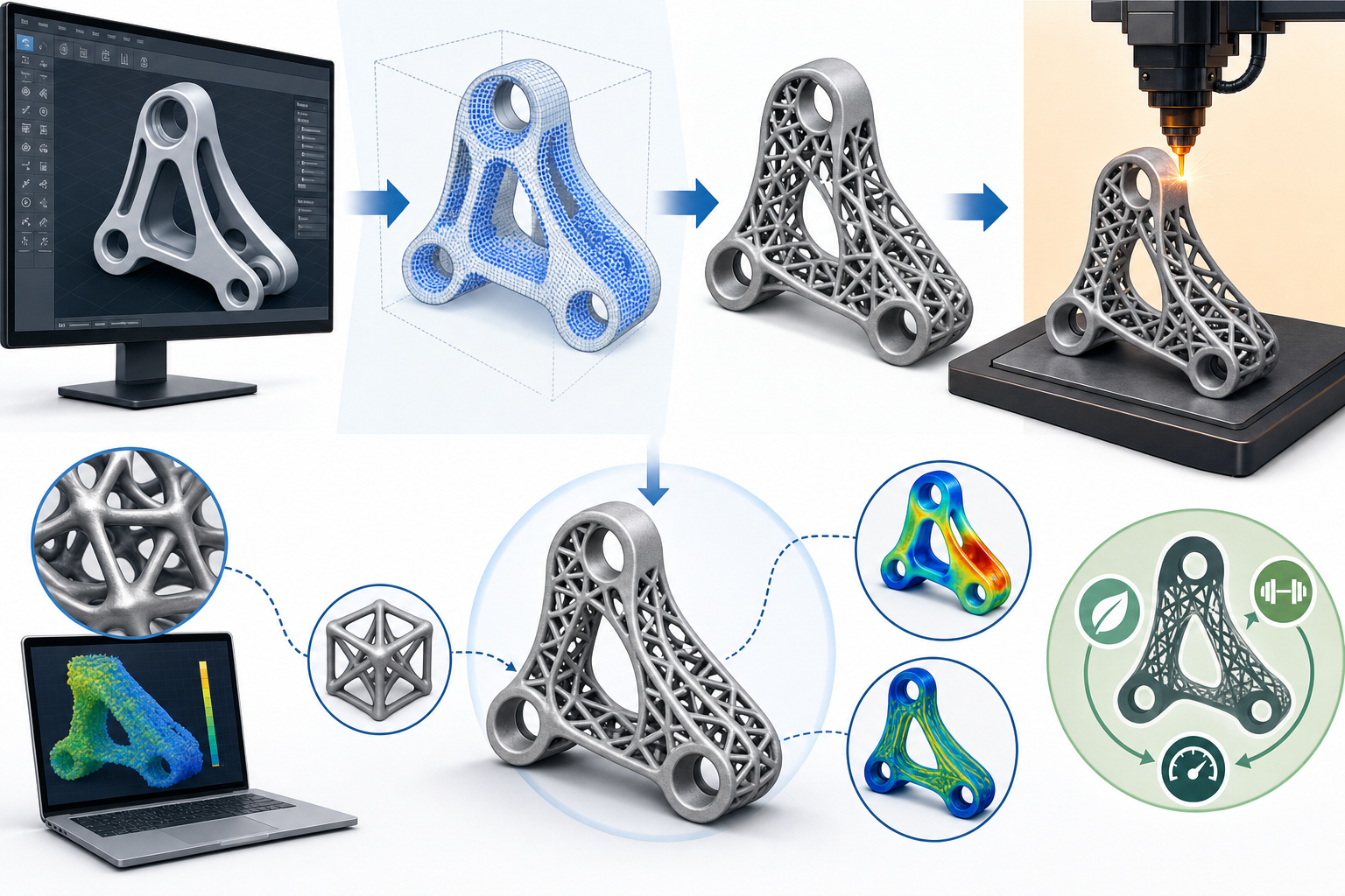


Generative patterns and lattice structures have moved from experimental geometry to a serious engineering strategy because they address problems that conventional solid modeling often handles inefficiently. The important shift is not simply aesthetic complexity. It is the ability to distribute material according to stress, thermal flow, impact loads, biological fit, or manufacturing constraints in ways that were previously impractical to model and even harder to produce. In that sense, additive manufacturing has done more than open a path to unusual forms. It has exposed the limitations of traditional CAD assumptions built around boundaries, prismatic features, and uniform material volumes, and it is pushing design software toward a more computational, field-based, and performance-driven future.
Why Lattices and Generative Patterns Are Fundamentally Different from Conventional Solid Modeling
Conventional solid modeling is built on a relatively stable idea of geometry: designers define surfaces, combine features, trim bodies, and specify dimensions that result in a mostly continuous mass. Even when parts are complex, the underlying logic remains feature-centric and boundary-driven. By contrast, lattice structures, cellular architectures, and generative patterns replace the assumption of uniform material with a distributed system of repeated or semi-repeated elements whose local behavior matters as much as the global shape. A lattice may consist of beam-based unit cells, triply periodic minimal surfaces, or graded cellular regions that transition across the volume of a component. Cellular structures can be stochastic, biomimetic, anisotropic, or tuned to regional load conditions. Generative patterns extend this logic further by using rules, fields, mathematical expressions, or optimization outputs to create geometry that responds to performance targets rather than being directly sketched in a traditional modeling environment.
Geometry Logic Beyond Boundaries
The distinction is important because traditional solid modeling usually treats the interior of a part as secondary. If the outer shell is correct and the manufacturing method can realize it, the internal volume often remains homogeneous. In advanced additive workflows, the interior becomes a design domain of equal importance. Software must therefore manage geometry not merely as a closed shell but as a controllable material distribution system. That requires new representation methods, new editing logic, and new performance feedback loops. The designer is no longer only asking what shape a part should have. The designer is asking where material should exist, at what density, with what orientation, under what local constraints, and with what relationship to mechanical or thermal objectives. This is why these structures are not just an extension of conventional CAD. They challenge the very way design intent is represented, parameterized, and updated.
Why These Geometries Matter Now in Additive Manufacturing
The current importance of these geometries comes from the convergence of manufacturing capability, computational power, and performance pressure. Additive manufacturing can fabricate shapes whose complexity is nearly impossible to machine economically, especially when internal architectures must vary throughout the part. That makes lattices relevant for lightweighting, where mass is removed without proportionally sacrificing structural stiffness. It makes them useful for energy absorption, where controlled deformation under compression or impact can outperform monolithic solids. It also makes them valuable for thermal performance because surface area, flow pathways, and conductive patterns can be tuned in ways that solid blocks cannot match. Material efficiency is another driver, especially when expensive alloys or engineered polymers are involved. Instead of filling a volume uniformly, teams can place material where it contributes most to performance, reducing both cost and weight while potentially shortening print times.
Customization as a Performance Strategy
Customization is equally significant. In medical, industrial, and consumer applications, there is growing demand for parts that respond to individual anatomy, specific load paths, or localized operational requirements. Lattices can be tuned for compliance in one region, rigidity in another, and permeability or porosity in a third. This means the geometry itself becomes a response mechanism. Several strategic benefits explain the urgency of adoption:
- Lightweighting without relying only on shell thinning or machined pockets
- Improved impact and crash management through controlled collapse behavior
- Higher thermal exchange efficiency through increased internal surface area
- Reduced raw material use in high-cost metal and polymer systems
- Patient-specific and performance-specific customization at the internal architecture level
What makes this moment different from earlier periods of design experimentation is that these goals are no longer theoretical ambitions. They are becoming procurement requirements and competitive differentiators. As a result, software is under pressure to support geometry that is not only infinitely complex in appearance but also deeply tied to engineering performance and manufacturing feasibility.
How Additive Manufacturing Is Forcing Design Software Beyond Traditional CAD Assumptions
The central transformation is that additive manufacturing does not simply reward complex forms. It forces software developers to rethink the data structures and workflows that support design. Traditional CAD systems were optimized for explicit geometry: surfaces, solids, sketches, and feature histories that remain manageable when part complexity is visually rich but topologically restrained. Lattice-heavy parts break this model because a simple bracket with a graded internal architecture may contain millions of geometric elements if represented explicitly. File sizes explode, regeneration becomes unstable, editing becomes brittle, and downstream translation introduces errors. More importantly, the design intent is usually not contained in each strut or cell individually. It is contained in rules, fields, and performance maps. That means design software must move from describing what every piece of geometry is to defining how geometry should be generated across a domain.
From Feature History to Computational Intent
This change represents a broader shift from feature-based drafting logic to computational design logic. Instead of building a model step by step in a fixed sequence, designers increasingly define objectives, constraints, and parameter relationships that drive geometric outcomes. Additive manufacturing intensifies this trend because it rewards parts whose internal and external forms are integrated. The software platform that succeeds is therefore not the one that simply adds a lattice command to a legacy CAD interface. It is the one that connects generative geometry, analysis feedback, manufacturability constraints, and production-aware parameter control in a coherent workflow. In practical terms, this means engineering teams need tools that can create a graded lattice from stress data, adjust cell orientation based on print direction, preserve editable parameters through design iterations, and export machine-ready definitions without collapsing the intelligence of the model into an unmanageable mesh. That is the true software challenge raised by additive manufacturing.
Implicit Modeling and Field-Driven Geometry Generation Are Making Complex Structures Usable
One of the most important capabilities enabling practical lattice design is implicit modeling. Instead of representing geometry strictly through explicit boundary surfaces, implicit methods define shapes mathematically as fields or volumetric functions. This is especially powerful when dealing with smooth transitions, complex internal cavities, triply periodic minimal surfaces, or highly graded cellular structures. Because the model is governed by equations and thresholds rather than countless discrete faces, software can handle far more complexity without becoming computationally unusable. Implicit workflows also make blending, trimming, thickening, and grading easier, which is critical for additive manufacturing where stress concentrations and geometric discontinuities can undermine performance. When a designer wants porosity to increase gradually across a volume or wants a lattice to merge smoothly into a solid interface region, implicit representations often provide a far more robust foundation than explicit solid operations.
Fields as Carriers of Performance Intent
Field-driven geometry generation extends this capability by assigning geometric behavior based on scalar or vector data such as stress magnitude, thermal gradients, anatomical mapping, or distance from a surface. In other words, the shape is informed by a performance field rather than manually prescribed cell by cell. Software can use these fields to control:
- Cell size variation across a part
- Density gradients from dense load zones to lighter secondary regions
- Orientation of unit cells relative to force direction or print strategy
- Wall thickness or beam diameter as a response to local criteria
- Transition smoothness between solid and porous regions
This matters because manual modeling of such variation is neither scalable nor reliable. A field-driven approach captures intent at the right level of abstraction. The designer adjusts rules and maps, and the software regenerates the internal architecture accordingly. That is what turns lattice design from a one-off digital sculpture into an editable engineering workflow suitable for product development.
Topology Optimization and Rule-Based Pattern Creation Are Reshaping Internal Architecture Design
Another major driver of adoption is the integration of topology optimization with lattice generation. Topology optimization traditionally identifies where material should remain or be removed within a design space under specified loads and constraints. For additive manufacturing, that result is increasingly being used not only to define external form but also to guide internal architecture. For example, regions identified as structurally critical may receive denser cellular networks, reinforced strut diameters, or lower-porosity surfaces, while low-stress volumes can transition into lighter and more open configurations. The practical value comes when software does not treat topology optimization and lattice design as disconnected tasks. Instead, the optimized field becomes an input for local pattern decisions, making internal architecture part of the same performance logic that shaped the part globally.
Rules That Make Variation Manageable
Rule-based pattern creation is equally important because not every effective structure emerges from optimization alone. Engineering teams often need repeatable logic that aligns with manufacturing standards, certification pathways, or product family reuse. Rule-based systems allow designers to define how patterns should propagate, what exceptions should occur near interfaces, and how geometric transitions should respond to specific thresholds. These rules can encode practical decisions such as:
- Maintaining denser lattice near bolt interfaces or load introduction points
- Reducing unsupported spans in overhang-sensitive print orientations
- Applying open-cell regions where powder evacuation is necessary
- Increasing local compliance where vibration damping is required
- Preserving skin thickness around sealing or finishing zones
The result is a workflow that combines generative flexibility with engineering discipline. Rather than manually remodeling each new part variant, teams can reuse logic, tune parameters, and regenerate structures with consistent intent. This is a major reason software is making complex lattice design practical: it reduces complexity by moving the design conversation from geometric micromanagement to controlled behavioral rules.
Simulation-Informed Parameter Control Is Turning Lattices into Engineering Systems
The most advanced software environments now treat lattices not as decorative infill but as engineering systems whose parameters can be informed directly by simulation. This is a significant maturity step. A lattice without feedback is simply complexity. A lattice whose beam thickness, unit cell topology, gradation, and directional alignment are tied to predicted performance becomes a tunable design mechanism. This is where editable parameters become strategically important. Cell size, relative density, orientation, transition rate, and wall thickness are not just modeling conveniences. They are the variables through which stiffness, mass, thermal response, deformation mode, and manufacturability can be negotiated. When simulation results can influence these variables automatically or semi-automatically, software begins to support genuine design iteration at the architectural level rather than only at the outer-shape level.
Editable Parameters as Decision Levers
Design teams increasingly need software in which these variables remain persistent and understandable throughout the workflow. That enables comparison across iterations and allows engineering rationale to survive into process planning and production. The most useful parameter controls often include:
- Cell size to influence local stiffness, printability, and powder removal behavior
- Density to balance lightweighting against load-bearing performance
- Gradation to transition between high and low performance zones smoothly
- Orientation to align architecture with principal stresses or print direction
- Node or wall thickness to mitigate fatigue risk and local stress concentration
When these controls are linked to simulation outputs, the software can help answer practical questions: which gradation profile best preserves stiffness-to-weight ratio, which cell orientation improves thermal transfer, and which density threshold creates unacceptable failure risk under cyclic loading. This level of control is what makes computational geometry compatible with engineering accountability.
Comparing Native CAD Tools, Specialized Additive Platforms, and Computational Design Environments
Not all software approaches lattice design from the same position, and the differences matter for implementation. Native CAD lattice tools are often the easiest entry point because they sit inside familiar modeling environments and simplify basic workflows. They are useful when teams want moderate internal complexity, straightforward parameter controls, and direct integration with assembly context or standard part modeling. However, they can become limiting when the project requires highly graded structures, field-based logic, or large-scale computational efficiency. Specialized additive manufacturing platforms usually go further by combining build preparation, lattice generation, support management, and process-aware checks in one environment. These are especially valuable when production constraints are central and when the software must handle large, detailed, or machine-specific geometries without degrading performance. They often provide stronger tools for process simulation, print orientation analysis, and export readiness.
Choosing the Right Workflow Depth
Computational design environments offer the greatest flexibility but also demand the highest level of technical fluency. They excel when teams want to script custom pattern logic, connect geometry to simulation fields, or build reusable generative systems across product lines. Their strength lies in abstraction and automation rather than out-of-the-box simplicity. In practice, the main workflow options can be understood as follows:
- Native CAD tools: best for accessible adoption and moderate complexity
- Specialized additive platforms: strongest for manufacturability integration and production readiness
- Computational design environments: best for custom logic, advanced automation, and research-grade control
Many mature teams use a hybrid approach. Early concept generation may happen in a computational environment, engineering refinement in CAD or CAE-linked platforms, and build preparation in a dedicated additive system. The strategic question is not which tool category is universally best. It is which environment preserves design intent while enabling iteration, validation, and manufacturing execution without forcing repeated geometry rebuilds or lossy translations.
Why Visually Impressive Lattice Designs Often Fail the Engineering Reality Test
There is a persistent gap between impressive lattice concepts and production-ready designs. The visual language of additive manufacturing can create the illusion that if a geometry is computationally elegant, it is also practical. In reality, many lattice-heavy designs fail because they were generated without enough attention to process constraints, post-processing access, inspection strategy, or realistic performance validation. An internal architecture may look highly optimized on screen while containing unsupported overhangs, unremovable powder traps, fragile nodes, or features below the process resolution threshold. In some cases, parts perform poorly not because the lattice idea was wrong but because the software workflow did not connect geometry generation to manufacturing physics. This gap is especially dangerous when design reviews focus on rendered complexity rather than measurable outcomes. Sophisticated internal structure alone does not guarantee mass savings, durability, or repeatability.
Complexity Must Earn Its Place
The engineering standard for these designs is therefore much higher than visual novelty. Every added layer of geometric complexity must justify itself through performance or production value. Teams need to ask direct questions:
- Does the lattice improve stiffness-to-weight meaningfully over a simpler alternative?
- Can the selected print process resolve the smallest features consistently?
- Will trapped powder, uncured resin, or inaccessible support compromise the part?
- Can the structure be inspected and validated without excessive cost?
- Do transitions between dense and sparse regions create local failure risk?
Advanced software becomes valuable precisely at this point. Its role is not to generate maximum complexity, but to discipline complexity through process-aware and performance-aware feedback. The best results come when software helps teams eliminate attractive but non-manufacturable ideas early and concentrate on architectures that can survive the realities of printing, cleaning, testing, and real-world loading.
Print Constraints, Support Strategy, and Post-Processing Are Central to Manufacturable Lattice Design
Manufacturable lattice design begins with an honest understanding of process limits. Different additive technologies impose different constraints on minimum feature size, unsupported span tolerance, surface roughness, thermal distortion, and enclosed cavity behavior. A beam diameter that works in one powder bed fusion system may fail in another due to melt pool instability or recoater interaction. A resin-based process may reproduce fine details well but create drainage challenges in enclosed cellular regions. Support strategy is also more complicated than it appears. External supports are only part of the issue. Internal geometry may generate inaccessible support requirements or overhang conditions that cause deformed cells, incomplete fusion, or cleaning problems. Even in processes where support is minimized, local heat buildup or shrinkage can distort thin lattice members and introduce dimensional inconsistency.
Designing for Removal, Access, and Surface Reality
Post-processing constraints often determine whether a lattice is useful in production. Powder removal in metal systems and resin drainage in photopolymer systems are not secondary concerns. They are design-defining constraints because internal channels and cell openness must allow material evacuation. Surface quality is similarly critical because roughness, partially fused particles, or stair-stepping can alter fatigue behavior and functional contact. Teams must therefore account for:
- Minimum printable wall and strut dimensions
- Orientation-sensitive overhang behavior
- Accessibility for support removal where needed
- Open pathways for powder removal or resin drainage
- Surface finish implications for fatigue, sealing, or biological contact
Software that embeds these constraints into the lattice generation process is far more valuable than software that defers them to a later review. If engineers can see unsupported regions, feature-size violations, or evacuation traps while adjusting pattern parameters, they can resolve manufacturability problems during design instead of discovering them after build failure or during costly rework.
Simulation and Validation Tools Are Essential for Proving Performance in Advanced Internal Architectures
As lattice use expands, the demand for credible validation increases. Standard finite element methods can struggle when every cell is represented explicitly, especially for large components or multi-scale structures. This has led to the development of specialized approaches such as homogenization methods, reduced-order representations, and multi-scale simulation strategies that estimate effective material properties without solving every geometric detail at full fidelity. These methods are essential because the engineering questions are not trivial. Teams need to evaluate stiffness-to-weight ratio, fatigue behavior under cyclic loading, impact absorption during crash or drop events, thermal transfer across distributed architectures, and failure risk in graded regions where abrupt changes in density or topology may create stress concentrations. Each of these behaviors depends not only on the chosen unit cell but also on print-induced variation, local defects, and surface condition.
From Concept Metrics to Reliable Validation
Validation tools help translate geometric ambition into engineering evidence. A useful workflow often combines several layers of assessment:
- Early-stage screening using effective property models for rapid iteration
- Detailed local analysis in critical regions such as interfaces and graded transitions
- Process-aware prediction of distortion or thin-feature vulnerability
- Physical testing correlation to calibrate simulation assumptions
- Inspection planning to verify that printed geometry matches computational intent
Inspection difficulty deserves particular attention because internal architectures are inherently harder to measure than external solids. Computed tomography, sectioning strategies, and surrogate coupons may all be needed depending on application criticality. The real message is that advanced software must support a chain of confidence. It should not stop at generating geometry. It should help establish whether the structure can be simulated meaningfully, printed repeatably, verified adequately, and trusted in service. Without that chain, lattice design remains an attractive concept rather than a mature engineering method.
The Real Value of Advanced Software Is Balancing Freedom of Form with Manufacturable Performance
The most important contribution of modern design software is not that it allows unlimited formal experimentation. Its deeper value is that it can mediate between geometric freedom and manufacturable performance. Additive manufacturing creates the temptation to chase complexity for its own sake, yet commercial success depends on parts that are lighter, stronger, more efficient, and realistically producible. Software becomes strategic when it turns internal architecture into a controllable engineering variable system rather than a fragile collection of hard-to-edit entities. That means preserving parameter intelligence, connecting geometry decisions to simulation feedback, exposing print constraints during design, and carrying model intent into build preparation and validation. In mature workflows, the lattice is not a decorative fill generated at the end. It is an integral part of the design definition, linked to material behavior, process capability, and functional requirements from the start.
Integration Is the Competitive Differentiator
This is why generative patterns and lattice structures represent a broader transformation in design thinking rather than merely a new modeling feature. The strongest competitive advantage will come from teams that can connect four capabilities into one coherent loop:
- Generative geometry that responds to performance objectives
- Simulation that informs architectural decisions rather than only validating final form
- Process-aware design rules that prevent non-manufacturable complexity
- Additive manufacturing execution that preserves design intent through print preparation and production
Looking ahead, the trajectory is clear. Software will move toward more automated lattice optimization, tighter CAD-CAE-AM integration, and increasing use of AI-assisted exploration to search high-performance internal architectures across vast design spaces. The teams that benefit most will be those that see these tools not as isolated features but as parts of a new digital engineering framework. In that framework, geometry is no longer just shape. It is a performance field, a manufacturing instruction, and a competitive strategy encoded into material distribution itself.
Also in Design News