
Your Cart is Empty


Design Software History: Slicing Software and the Evolution of Additive Manufacturing Design Workflows
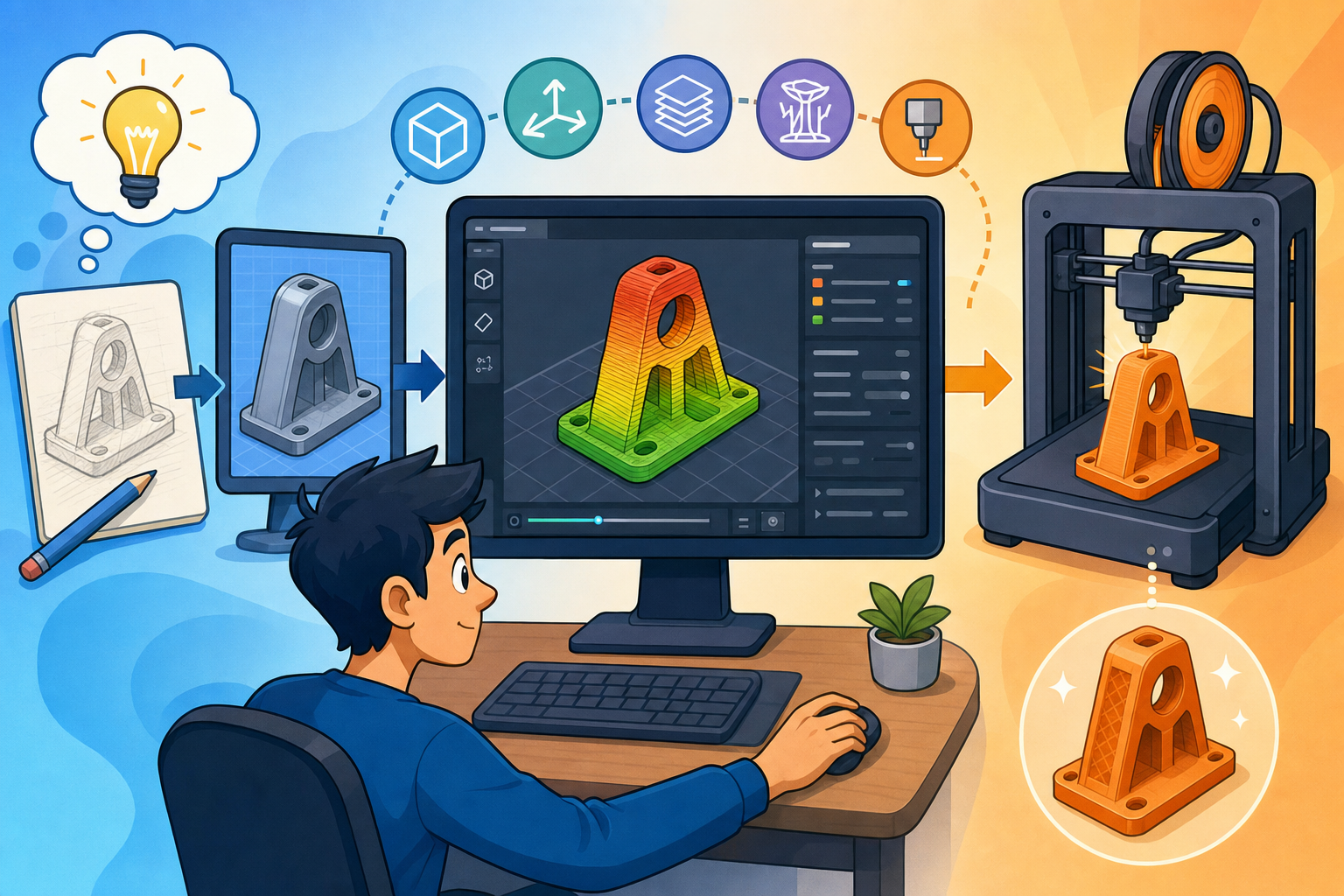


The history of slicing is the history of a quiet but decisive shift in design software: the moment when digital geometry stopped being merely a representation of an object and became an executable manufacturing plan. In additive manufacturing, the finished CAD model is not the end of the design process; it is the beginning of a second interpretation, where software decides how matter will be deposited, cured, fused, or bound layer by layer.
From CAD Geometry to Physical Layers: The Birth of Slicing
The Practical Origins of Layered Manufacturing Software
Slicing did not emerge from the traditional agenda of CAD vendors, whose principal goal through the 1960s, 1970s, and early 1980s was to describe geometry accurately for drafting, engineering analysis, and subtractive manufacturing. It emerged from the practical needs of early additive manufacturing machines, which could not fabricate an abstract solid model directly. A CAD system such as CATIA from Dassault Systèmes, Unigraphics from McDonnell Douglas and later EDS, Pro/ENGINEER from Parametric Technology Corporation, or early solid modeling systems built around boundary representation could define ideal surfaces and volumes, but a machine that cured resin or extruded thermoplastic needed a different kind of information. It needed a sequence of layers, tool movements, exposure regions, and machine instructions. This created a new software problem: how to translate continuous geometry into discrete physical actions. The emergence of slicing was therefore not simply a file conversion story. It was the creation of an algorithmic manufacturing interpreter that stood between the mathematically ideal world of CAD and the mechanical realities of additive fabrication.
Chuck Hull, 3D Systems, and the STL Bridge
The late 1980s were decisive because Chuck Hull and 3D Systems turned stereolithography from an experimental concept into a commercial process. Hull’s work, beginning with his 1984 patent application and the founding of 3D Systems in 1986, demonstrated that ultraviolet light could selectively cure thin layers of photopolymer resin into physical parts. This process demanded a digital pipeline unlike the pipelines used for NC machining or engineering drawings. CAD models had to be reduced to a form that early machine software could process reliably on the computers of the period. The result was the STL file format, commonly interpreted as “stereolithography” or “standard tessellation language,” a deliberately simple format that represented a model as a collection of triangular facets. STL ignored feature history, exact analytic surfaces, topology-rich boundary representation, color, material intelligence, and design intent. Yet its simplicity was precisely why it mattered. It became a rough, portable bridge between heterogeneous CAD systems and additive machines, allowing geometry from many sources to enter the same slicing workflow.
Why Ideal CAD Solids Were Not Enough
The importance of slicing becomes clear when one considers the mismatch between a CAD model and a layered machine. A solid model describes an object as if it exists all at once, with surfaces, edges, and volumes defined continuously in mathematical space. A stereolithography apparatus, by contrast, builds the object as a stack of cross sections. It does not understand the designer’s fillets, sketch constraints, parametric feature tree, or surface continuity in the same way the CAD system does. It needs to know where each layer boundary lies, which regions of resin should be exposed, where support structures must be created, and how the machine should move or scan. In this sense, slicing was a new form of manufacturing reasoning. It converted a nominal design into a process plan and introduced a level of interpretation that designers could not ignore. Slicing turned design software from a tool for describing objects into a tool for manufacturing them directly, and that historical shift remains one of the most important developments in digital fabrication.
The Algorithmic Core: How Slicers Turn Solids into Toolpaths
From Mesh Import to Layer Contours
The basic slicing workflow begins with the import of a geometric model, historically most often an STL mesh. The slicer receives a collection of triangles, each with vertex coordinates and a surface normal, and then intersects that faceted object with a stack of horizontal planes. Each plane corresponds to a layer height, such as 0.1 millimeters, 0.2 millimeters, or a variable height determined by the software. The mathematical operation sounds simple: find where each triangle crosses a plane, create line segments, and assemble those line segments into closed contours. In practice, this is one of the defining computational tasks of additive manufacturing. Each two-dimensional contour describes the boundary of material to be created at that layer. These contours must then be classified, nested, oriented, and converted into paths suitable for the specific technology, whether a laser scan in stereolithography, an extrusion path in fused deposition modeling, or a contour exposure region in powder-bed fusion. The ability to produce valid contours consistently became the foundation of reliable additive manufacturing preparation.
Offsets, Perimeters, Infill, and Machine Instructions
After contours are generated, the slicer must turn them into practical toolpaths. For extrusion-based processes, the outer boundary is usually offset inward to create perimeters or shells, often called walls. Additional offsets may define inner perimeters, while remaining areas are filled with infill patterns such as rectilinear grids, honeycombs, gyroids, triangles, cubic structures, or adaptive patterns based on expected loads. In stereolithography or selective laser sintering, the same conceptual problem appears in a different form: boundary scans, hatch patterns, exposure strategies, and scan spacing must be calculated. The slicer also identifies overhangs and unsupported regions, then generates support structures to prevent deformation, collapse, resin islands, or failed deposition. Finally, the planned paths are converted into machine instructions, often G-code in desktop fused filament fabrication, although industrial systems may use proprietary formats and build processors. This final translation includes speeds, temperatures, extrusion rates, retraction commands, laser power, exposure timing, fan behavior, tool changes, and coordinate movements. The slicer therefore functions as a geometry engine, a process planner, and a machine controller translator at the same time.
The Geometry Problems Hidden Inside Slicing
The geometric problems inside slicing are numerous and historically underestimated. Triangle-plane intersection requires careful handling of triangles that lie exactly on a slicing plane, vertices that coincide with a plane, and edges that produce ambiguous intersections. Once line segments are generated, polygon reconstruction must connect them into coherent loops, even when the original STL contains small gaps, inverted normals, duplicated facets, or degenerate triangles. Contour nesting determines which polygons are exterior boundaries and which are holes, while polygon orientation helps the software distinguish solid regions from voids. Self-intersections create another layer of difficulty because a model may appear visually correct in a CAD viewer while being mathematically invalid for manufacturing. Non-manifold meshes are especially problematic because a physical solid should have each edge shared by exactly two faces in a watertight surface, but STL files often contain edges shared by one, three, or more triangles. These failures force slicers to make interpretive decisions. Numerical robustness is equally important because floating-point tolerances can determine whether a contour closes or whether a tiny feature disappears. In short, slicing exposed the fragile boundary between visual geometry and manufacturable geometry.
Mesh Repair and the Expansion of Slicer Responsibility
Early STL files were often flawed because CAD systems exported tessellations with limited awareness of the strict requirements of additive manufacturing. Designers could select coarse chord tolerances, generate faceted approximations with gaps, or export assemblies with overlapping components. As a result, slicers and preparation tools gradually became responsible for geometry healing. This responsibility was not originally central to the idea of slicing, but it became unavoidable. Materialise Magics, developed by the Belgian company Materialise founded by Wilfried Vancraen, became one of the most influential industrial platforms precisely because it treated build preparation, mesh repair, part orientation, support generation, labeling, nesting, and production management as serious software disciplines. Magics helped professionalize the preparation stage by providing tools for repairing bad meshes, thickening weak regions, hollowing parts, creating drainage holes, and preparing complex builds. In the desktop world, mesh repair was eventually integrated into slicers and related utilities, reducing the burden on users. The historical lesson is clear: once additive manufacturing became practical, slicers could not remain passive readers of CAD data; they had to become active interpreters and repairers of imperfect design information.
Companies, Open-Source Projects, and the Desktop Printing Era
The field was shaped by both proprietary industrial systems and open-source experimentation. 3D Systems developed early proprietary workflows around stereolithography, while Stratasys, founded by Scott Crump and Lisa Crump, built software around fused deposition modeling after Scott Crump invented the process in the late 1980s. These industrial pipelines were closely tied to machine behavior and materials. Later, the RepRap project, initiated by Adrian Bowyer at the University of Bath, radically broadened the culture of slicing by encouraging open, low-cost desktop 3D printing. Skeinforge, created by Enrique Perez, became one of the early influential open-source slicing engines despite its complexity. Slic3r, originally developed by Alessandro Ranellucci, brought a more approachable and powerful toolpath generation approach to RepRap-style machines. Cura, developed by David Braam and later advanced by Ultimaker, made slicing accessible to a much larger desktop audience. PrusaSlicer, derived from Slic3r and developed by Prusa Research, became a sophisticated modern slicer tied to a deep knowledge of printers, materials, profiles, and user workflows. Together, these projects transformed slicing from an obscure industrial necessity into a visible part of everyday digital making.
From Utility Software to Design Technology
When Slicers Began to Influence Design Decisions
As additive manufacturing matured, slicers moved beyond being simple machine-preparation utilities and began influencing design itself. Designers learned that a model can be geometrically correct and still be difficult, expensive, weak, ugly, or impossible to print. Wall thickness became a design constraint because a wall thinner than the nozzle width, laser spot size, or material process limit may vanish or become fragile. Overhang constraints encouraged designers to add chamfers, redesign unsupported features, or orient parts differently. Support minimization became a design objective because supports consume material, increase build time, damage surface finish, and complicate post-processing. Print orientation changed mechanical performance because layer adhesion, surface stair-stepping, support placement, and build time all depend on how the object sits in the machine. Infill density and pattern selection changed weight, stiffness, energy absorption, and print duration. Layer height became a tradeoff between surface finish and productivity. These choices are not merely manufacturing settings after design; they are design decisions expressed through slicing parameters. The slicer became a place where geometry, material behavior, machine limits, and aesthetic expectations were negotiated.
Adaptive Layers, Variable Infill, and Smarter Toolpaths
Advanced slicing methods deepened this influence. Adaptive layer height algorithms vary the thickness of layers according to local geometry, using thinner layers on shallow slopes or curved surfaces where stair-stepping would be visible and thicker layers in vertical or less critical regions to save time. Variable infill allows the internal structure of a part to change spatially, concentrating material near fastening points, load paths, or impact zones while reducing material elsewhere. Multi-material slicing introduces another level of complexity because the software must assign paths to different print heads, nozzles, resins, powders, or deposition systems, as well as handle purging, tool changes, contamination, and material interfaces. Support generation algorithms evolved from simple vertical scaffolds into tree supports, soluble support strategies, breakaway lattices, cone supports, and process-specific structures for resin, powder, and metal printing. Non-planar slicing challenges the traditional assumption that every layer must be horizontal, allowing curved layer paths that can improve surface quality or align deposition with mechanical forces. Toolpath-aware design optimization goes further by designing geometry with knowledge of how the machine will actually fabricate it. These developments show that slicing became a central engine of manufacturability-aware modeling.
The Blurring Boundary Between CAD, CAM, and Simulation
Traditional CAD focused on nominal geometry: the ideal intended shape of the product. CAM focused on generating manufacturing instructions, especially for milling, turning, drilling, and other subtractive operations. Simulation focused on predicting stress, heat, fluid flow, motion, or deformation. Slicing disrupted these categories because additive manufacturing preparation requires all three perspectives at once. A slicer reads geometry like CAD software, generates machine instructions like CAM software, and increasingly incorporates process knowledge that resembles simulation. Metal additive manufacturing made this especially important because thermal gradients, residual stresses, recoater interference, support conductivity, and distortion compensation cannot be treated as afterthoughts. Software systems began to include build simulation, orientation optimization, support optimization, and compensation geometry. Autodesk Netfabb, which grew from the German company netfabb before Autodesk acquired it, became a major platform for additive preparation, repair, support generation, packing, and simulation-oriented workflows. Dassault Systèmes, Siemens, and PTC all moved additive manufacturing capabilities into broader CAD, CAM, CAE, and PLM ecosystems, recognizing that additive preparation could not remain isolated from product definition, process planning, enterprise traceability, and lifecycle management. The slicer became a bridge across disciplines that earlier software categories had kept separate.
Modern Tools and Their Different Philosophies
Modern slicers and additive preparation platforms embody different philosophies about how much control should be given to users and how deeply the tool should integrate with design. Ultimaker Cura emphasizes accessibility through profiles, material presets, marketplace extensions, and a user interface that can serve beginners while still exposing many parameters to experts. PrusaSlicer combines advanced features such as modifier meshes, variable layer height, paint-on supports, seam control, multi-material workflows, and detailed printer profiles with a culture shaped by the RepRap and Prusa Research communities. Simplify3D built its reputation on user control, custom support generation, process settings, and visual path preview at a time when desktop 3D printing needed more reliable preparation tools. Autodesk Netfabb serves industrial users who need repair, packing, lattice tools, additive process preparation, and integration with other Autodesk manufacturing products. nTopology approaches additive manufacturing from a different direction: instead of treating lattices and fields as afterthoughts, it provides implicit and field-driven modeling tools for complex internal structures, graded materials, lightweighting, and high-performance design. In larger ecosystems, Dassault Systèmes, Siemens, and PTC connect additive preparation to parametric design, simulation, product data management, and manufacturing execution. This variety shows that slicing is not one monolithic technology but a family of design-manufacturing interpretations.
Lattices, Fields, and the New Internal Geometry of Products
One of the most profound effects of slicing on design software is the growing importance of internal geometry. Traditional manufacturing often made internal complexity expensive or impossible, so CAD models tended to represent solid, shell, or machined forms. Additive manufacturing made internal lattices, graded densities, conformal channels, porous structures, and cellular materials practical, but these features also stressed conventional CAD kernels and STL workflows. A lattice-heavy design may contain millions or billions of struts, surfaces, or cells, making explicit boundary representation inefficient. This is why implicit modeling, field-driven geometry, and voxel-like approaches have become increasingly important in additive workflows. nTopology is particularly associated with this shift, using mathematical fields to define geometry that can vary smoothly according to performance requirements. Slicers then become critical because the machine does not need a human-readable model of every internal beam in the traditional CAD sense; it needs manufacturable cross sections or paths. The more complex the internal structure, the more important the slicing strategy becomes. In this environment, the distinction between designing a shape and designing a material distribution begins to collapse, and slicing becomes the mechanism that gives that distribution physical form.
Why Slicing Became Central to Digital Fabrication
From Necessary Conversion Step to Manufacturing Intelligence
Slicing began as a necessary conversion step for early 3D printers, especially in the context of stereolithography and the STL-based pipelines created around 3D Systems machines. Its original task was modest in concept: take a faceted model, cut it into layers, and generate instructions for a machine. Yet that simple idea expanded into a sophisticated layer-based manufacturing intelligence system. Modern slicers do not merely cut geometry. They repair meshes, analyze overhangs, determine support structures, select wall strategies, generate infill, manage multi-material transitions, estimate print time, predict weak regions, expose errors, preview toolpaths, and encode machine behavior. They have absorbed knowledge that once might have belonged to machine operators, manufacturing engineers, CAD specialists, and process developers. This historical progression reflects a broader pattern in design software: once a digital tool becomes responsible for a critical transition in the product lifecycle, it accumulates intelligence. Because slicing controls the transition from digital model to physical build, it inevitably became one of the most consequential technologies in additive manufacturing.
The CAD Model Is Not the Finished Additive Design
The larger lesson is that in additive manufacturing, the design is not complete when the CAD model is finished. A parametric model may define dimensions, constraints, features, and surfaces, but the slicer determines how those intentions meet machine physics. It decides how many walls are printed, how the interior is filled, where seams appear, how supports touch the part, how the machine accelerates around corners, how heat accumulates, and how each layer relates to the previous one. Two parts with identical CAD geometry may have very different mechanical behavior, appearance, cost, and reliability depending on slicing parameters. A functional bracket printed with sparse infill may fail where the same geometry printed with dense infill or reinforced perimeters would survive. A resin part may exhibit different surface quality depending on orientation and support placement. A metal part may distort if the build strategy ignores thermal behavior. These examples demonstrate that the slicer interprets, modifies, and operationalizes the design. It is not a neutral export button; it is part of the design process itself.
STL’s Limitations and the Pressure for Better Representations
Slicing algorithms also helped expose the limitations of STL and mesh-based workflows. STL succeeded historically because it was simple, widely supported, and easy for early software to parse, but its weaknesses became increasingly obvious. It contains no reliable units unless inferred by convention, no material properties, no color, no manufacturing intent, no feature semantics, and no exact analytic geometry. Curves are approximated by triangles, which means accuracy depends on tessellation settings rather than the original CAD definition. A coarse STL may visibly facet a cylinder, while an excessively fine STL may burden software with unnecessary data. The format also allows invalid geometry, including holes, self-intersections, flipped normals, and non-manifold edges. As additive manufacturing matured, alternatives such as AMF, 3MF, and richer proprietary build formats attempted to address some of these limitations by carrying materials, colors, units, multiple objects, textures, and more structured data. Microsoft, Autodesk, Dassault Systèmes, Ultimaker, HP, and others participated in the 3MF Consortium to improve exchange for modern additive workflows. The pressure for better formats arose because slicers revealed what STL could not express.
Toolpaths, Supports, Infill, and Machine Physics as Design Concerns
The history of slicing shows that digital fabrication forces designers to think beyond visible shape. Toolpaths influence strength because extrusion direction, bead bonding, raster orientation, and seam placement affect how a part behaves under load. Supports influence not only print success but also surface quality, labor, and dimensional accuracy. Infill changes the relationship between outer geometry and internal performance, allowing one model to behave like a lightweight shell, a stiff cellular structure, or a nearly solid component. Machine physics adds still more constraints: molten polymer cools and shrinks, photopolymer resin needs exposure and drainage, powder-bed fusion involves thermal history and powder removal, and binder jetting requires depowdering and sintering compensation. Slicing brings these issues into the design conversation because it is the software layer where such choices are made visible and actionable. The significance of this development is historical as well as technical. CAD once promised that digital models could define products with precision. Additive slicing revealed that precision alone is insufficient; manufacturing behavior must be embedded into the digital workflow.
The Crucial Moment Where Geometry Becomes Matter
Slicing became a core design technology because it controls the crucial moment where digital geometry becomes physical matter. It stands at the intersection of mathematical representation, computational geometry, machine control, materials science, and design intent. Its origins in the late 1980s were pragmatic: Chuck Hull’s stereolithography technology and 3D Systems’ STL-based workflows needed a way to convert CAD surfaces into layers. Its evolution through Stratasys systems, Materialise Magics, RepRap tools, Skeinforge, Slic3r, Cura, PrusaSlicer, Simplify3D, Autodesk Netfabb, nTopology, and enterprise CAD/PLM platforms turned it into a central component of digital manufacturing. The most important point is not that slicers make 3D printers run, although they do. The deeper point is that slicers changed what it means to finish a design. A design now includes not only nominal geometry but also orientation, layer strategy, support logic, internal structure, toolpath planning, material behavior, and machine constraints. In additive manufacturing, the slicer is where the ideal object becomes a buildable object, and that is why its history belongs at the center of design software history.
Also in Design News






