Your Cart is Empty
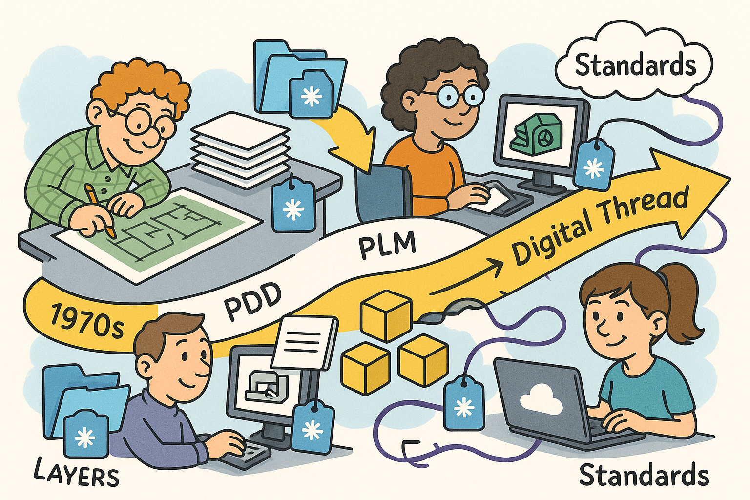
Design Software History: From Layers to the Digital Thread: Evolution of Metadata in CAD, PDM, PLM and Standards (1970s–Today)


Origins of Metadata in CAD and PDM (1970s–1990s)
Ad hoc beginnings
Before product data had formal homes, engineers smuggled meaning into the drawing file itself. In the late 1970s and 1980s, systems like AutoCAD from Autodesk (founded by John Walker), CADAM (born at Lockheed, later commercialized by IBM), CATIA V4 at Dassault Systèmes under Francis Bernard, and Unigraphics (originating at McDonnell Douglas, later EDS) relied on layers, blocks/macros, attributes, and text notes to encode part numbers, materials, and release status. These constructs were intended for drafting and graphical organization, yet teams used them as proto-metadata. A layer named “MAT-AL6061” doubled as a material declaration; a block attribute “PN=123-456-789” functioned as an internal part identifier; text near the title block conveyed drawn-by and checked-by information. This worked as long as conventions held and tribes stayed small, but the lack of structured fields and stable identifiers made automation brittle. IGES (Initial Graphics Exchange Specification), coordinated by the U.S. National Bureau of Standards (now NIST) with industry support, provided a lifeline for neutral exchange by carrying geometry and some annotations. However, semantics mostly traveled as generic entities or text strings, with meaning reconstructed through naming schemes rather than machine-readable models. In practice, the shop floor relied on people and paper to interpret intent. Ad hoc rules proliferated across organizations because they were easy to adopt, but they embedded meaning in places CAD kernels and downstream tools could not reliably parse, planting the seed for decades of conversion scripts, layer maps, and custom translators that blurred the boundary between data and metadata in engineering workflows.
- Layers and names served as quasi-databases for material, revision, and ownership.
- Block attributes captured part numbers and proprietary status codes without schema.
- IGES transported geometry broadly, but its semantic payload was thin and informal.
Early enterprise context
As programs scaled—particularly in aerospace and defense—the limits of ad hoc conventions became operational risks. Product Data Management (PDM) emerged to manage revisions, approvals, and configurations through structured attributes. Systems such as Metaphase (originating at SDRC), MatrixOne (later part of Dassault Systèmes ENOVIA), and SmarTeam (acquired by Dassault Systèmes) introduced database-backed items with typed fields for part/assembly identifiers, lifecycle states, and change orders. These platforms encoded workflows around Engineering Change Notice (ECN) processes and Bills of Materials (BOMs), finally giving metadata a first-class home. Yet schemas were proprietary and often tuned to a single vendor’s worldview. Meanwhile, large customers—especially the U.S. Department of Defense through CALS initiatives, and OEMs like Boeing and General Electric—pushed for neutral definitions to ensure multi-decade interoperability. PDES, Inc., a non-profit formed to coordinate users and vendors, became a crucible for neutral product modeling. The tension between proprietary PDM structures and the need for cross-vendor continuity shaped the 1990s landscape: enterprises demanded that metadata outlive any one tool, while vendors sought to balance open exchange with product differentiation. Integration was typically realized via brittle point-to-point mappings and custom ETL pipelines. Nevertheless, the era established the strategic premise that structured attributes, configuration control, and change management were the bedrock of trustworthy digital product definitions, even if the pipes between systems were still fragile and bespoke.
- PDM normalized attributes like part family, effectivity, and release status across programs.
- Change control workflows encoded approvals, signatures, and traceable reasoning.
- PDES, Inc. convened OEMs and software makers to converge on neutral semantics.
Seeds of semantic thinking
While CAD and PDM were stabilizing, language for tolerances and product definition matured. ASME Y14.5 codified Geometric Dimensioning and Tolerancing (GD&T), giving industry a rigorous vocabulary for form, fit, and function. The breakthrough was not only clearer drawings but the aspiration that this vocabulary might be machine-interpretable. Instead of reading symbols and notes, downstream software could ingest tolerances, datum schemes, and feature control frames as data. By the late 1990s, voices inside OEMs and standards bodies argued for models that embed “design intent” directly into the 3D representation, anticipating Model-Based Definition (MBD). The thread ran through aerospace, automotive, and high-tech: companies wanted to connect design, manufacturing, inspection, and supplier collaboration without serializing intent through 2D drawings. These seeds of semantic modeling dovetailed with NIST research programs and PDES, Inc. agendas, setting a direction toward a future where PMI (Product and Manufacturing Information) and configuration metadata ride alongside precise geometry. They also influenced vendor roadmaps—PTC’s emphasis on intent in Pro/ENGINEER, Dassault Systèmes’ functional tolerancing concepts, and Siemens’ feature-based modeling in Unigraphics/NX—by making it clear that geometry alone would not drive automation. The conceptual foundation was in place: an emerging consensus that drawings should be views of the model, not the model of record; and that the model must capture tolerances, materials, processes, and relationships as data that downstream machines could trust.
- ASME Y14.5 provided a formal grammar for GD&T essential to automation.
- Feature-based modeling linked CAD geometry with functional and manufacturing intent.
- MBD was foreshadowed by calls for PMI that systems—not just humans—could read.
The Standardization Wave: Making Metadata Machine-Readable (1990s–2010s)
STEP (ISO 10303) as the backbone
ISO 10303, known as STEP, set out to define a comprehensive, computer-interpretable representation of product data across the lifecycle. Application Protocols (APs) delineated domain scope: AP203 for configuration-controlled design, AP214 for automotive design processes, and eventually AP242 as their convergence focused on unified configuration, geometry, and PMI. AP242 consolidated identifiers, references, and validation properties, enabling persistent IDs and unambiguous cross-referencing among features, annotations, and assemblies. This was not merely a file format; it was an ontology of engineering artifacts aligned with EXPRESS schemas. NIST contributed conformance test suites and round-robin trials, while PDES, Inc. orchestrated implementer forums where vendors debugged interpretations in public. STEP Tools, led by Martin Hardwick, provided toolkits that reduced the cost and risk of high-fidelity implementations, accelerating adoption by Airbus, Boeing, Siemens, Dassault Systèmes, PTC, Autodesk, and Bentley. The practical impact was profound: a receiving system could validate that geometry and PMI were complete, that references were intact, and that changes could be diffed reliably from one configuration to the next. As editions matured, AP242 strengthened its coverage of kinematics, composites, and implementation methods for semantic PMI, moving industry closer to a world where product metadata was not a sidecar but a first-class aspect of the model, interoperable across design, manufacturing, and quality ecosystems.
- AP242 unified AP203/AP214, prioritizing IDs, references, and validation properties.
- NIST, PDES, Inc., and STEP Tools built the testing and toolkit backbone for adoption.
- Major vendors integrated AP242 into export/import and server-side pipelines.
Representing PMI and MBD
With geometry harmonized, attention turned to PMI. ASME Y14.41 and ISO 1101 provided digital rules for presenting and interpreting GD&T in 3D, bridging the gap between drafting-style symbology and semantic models that software can reason over. AP242 and JT (standardized as ISO 14306) became primary carriers for semantic PMI, supporting annotations linked to model faces, edges, and features with stable references. This mattered because misaligned notes and ambiguous references had historically caused downstream errors. At the same time, 3D PDF, standardized as ISO 32000 and empowered by the PRC geometry format (ISO 14739-1), pushed MBD beyond CAD power users to suppliers, procurement, and quality teams. Adobe, Tech Soft 3D, and partners such as Tetra4D popularized 3D PDFs with embedded views, section cuts, and data tables, all while preserving PMI semantics from native CAD and STEP/JT sources. The combination—AP242/JT for fidelity and authoring pipelines, 3D PDF for broad dissemination—aligned back-office PDM, supplier collaboration, and shop-floor visualization around a shared model of record. This alignment did not eliminate interpretation challenges, but it shifted the burden from reading drawings to consuming annotated, machine-linked models capable of driving downstream CMM programming, CAM feature mapping, and automated checks for completeness and consistency.
- ASME Y14.41 and ISO 1101 harmonized 3D presentation and interpretation of GD&T.
- AP242 and JT standardized references from PMI to precise geometric targets.
- 3D PDF extended MBD beyond CAD seats, preserving semantic links in accessible packages.
Quality and manufacturing semantics
Quality information needed its own backbone. The Dimensional Metrology Standards Consortium (DMSC) created the Quality Information Framework (QIF), an ANSI standard designed to capture measurement plans, actuals, and statistical results in a linked, XML-based model. QIF stitched the loop from CAD PMI to instrument programs and inspection results, enabling traceability across CMM, laser scanning, and portable metrology workflows. NIST supported the ecosystem with early reference implementations, test cases, and public challenges that clarified interoperability edge cases. On the manufacturing side, STEP-NC (ISO 14649 and ISO 10303-238) aimed to replace G-code with object-based definitions of features, processes, and machining strategies. Rather than programming machines with lines of motion, engineers could communicate intent: pockets, contours, tolerances, and toolpaths rooted in product geometry. Siemens NX CAM, Mastercam, and research partners, including Boeing and Sandvik, piloted STEP-NC lines to explore adaptive machining and closed-loop feedback from in-process measurements. Although G-code remains dominant on many shop floors, STEP-NC established a template for representing manufacturing intent explicitly, opening doors to optimizations that reason over semantically rich definitions rather than opaque instruction streams. Together, QIF and STEP-NC illustrated how domain-focused standards, linked to AP242, could carry the digital thread beyond design into verification and execution with measurable gains in automation and quality.
- QIF connected PMI to planning, execution, and statistical quality analysis.
- NIST’s reference work grounded implementers in shared examples and tests.
- STEP-NC modeled features and processes, elevating CNC programming from motion to intent.
Vendor-neutral and vendor-led exchanges
Not every exchange scenario fits a heavyweight standard. Vendors introduced formats that bridged practical needs while remaining open enough for integration. Siemens’ PLM XML exposed product structures, configurations, and lightweight geometry as a vendor-neutral XML representation, easing exchange across Teamcenter and partner systems. Dassault Systèmes’ 3DXML, likewise, carried geometry and metadata for ENOVIA/3DEXPERIENCE ecosystems. Most consequentially, JT—formalized as ISO 14306—became a de facto visualization and PMI carrier across Teamcenter and supplier networks, balancing file size with essential semantics and rich referencing. These formats did not replace STEP/IFC but complemented them, especially for visualization, supplier review, and data federation use cases where speed and footprint matter. The strategy was pragmatic: provide structures that can be extended without fracturing the core, maintain stable identifiers where possible, and document mappings to foundational standards. This tiered approach—AP242 for authoritative neutral exchange, JT/PLM XML/3DXML for high-velocity flows—helped enterprises rationalize toolchains without imposing a single monolithic schema everywhere. It also influenced API design, nudging platforms toward evented, metadata-rich payloads that could traverse PLM, MES, and quality systems with minimal custom glue while preserving concurrent access and configuration context.
- PLM XML and 3DXML simplified product structure exchange with extensible metadata.
- JT struck a balance between speed and semantic fidelity for visualization plus PMI.
- Layered exchange strategies reduced lock-in while keeping workflows performant.
Cross-Domain Semantics and the Digital Thread (2010s–today)
BIM and the AEC parallel track
Architecture, Engineering, and Construction (AEC) ran a parallel, sometimes intersecting journey through buildingSMART’s IFC (ISO 16739). IFC standardized building elements (e.g., IfcWall, IfcDoor), property sets, and relationships like containment and connectivity, enabling model-centric coordination among architects, engineers, and builders. COBie provided a structured subset for handover, and ISO 19650 established principles for information management across project phases. The intellectual roots run back to Professor Chuck Eastman at Georgia Tech, whose advocacy for model-centric building descriptions in the 1970s and 1980s anticipated today’s Building Information Modeling. Vendors like Graphisoft (founded by Gábor Bojár), Autodesk, Tekla (later part of Trimble), Nemetschek, and Bentley Systems (led for years by Keith Bentley) baked IFC and property/relationship-centric design into their ecosystems, while owner-operators demanded long-term access independent of authoring tools. IFC’s use of globally unique identifiers and explicit relationships paralleled AP242’s emphasis on identity and reference integrity. The connection to manufacturing grew as industrialized construction, modularization, and offsite fabrication expanded, demanding mappings from IFC to CAM and robotic assembly. The lesson for product industries is clear: a single discipline’s model is insufficient for execution; supply chains need property-rich, reference-stable models to coordinate across trades, phases, and contractual boundaries without degrading intent or provenance.
- IFC standardized elements, property sets, and relationships for building models.
- COBie and ISO 19650 matured delivery and information management practices.
- Eastman’s model-centric vision influenced vendors and standards alike.
Systems engineering to manufacturing execution
The digital thread stretches upstream into systems engineering and downstream to operations. SysML, under the Object Management Group (OMG), formalized requirement, function, and structure relationships, and SysML v2 brings a stronger semantic foundation with an API-centric orientation. ReqIF, originally propelled by ProSTEP iViP and later managed by OMG, supports requirement exchange across tools like IBM DOORS, PTC Integrity/Windchill RV&S, and Jama Software. Behavioral models packaged via FMI/FMU (from the Modelica Association) enable cross-tool simulation, while PLCS (ISO 10303-239) addresses through-life support semantics for configuration, maintenance, and logistics. On the runtime side, OPC UA (IEC 62541) provides a platform-independent, semantically extensible protocol for industrial data, and the Asset Administration Shell (AAS), coordinated by the Industrial Digital Twin Association (IDTA) under Germany’s Plattform Industrie 4.0, defines asset-centric submodels that link operational state to engineering metadata. The convergence of these layers means a requirement in SysML can be traced to a CAD feature, to a PMI callout, to a QIF measurement result, and ultimately to operational telemetry exposed via OPC UA/AAS. Realizing this chain at scale requires consistent identifiers, explicit relationships, and semantically aligned APIs, shifting emphasis from files to evented, graph-like representations that preserve intent and context as information flows across lifecycle stages and organizational boundaries.
- SysML v2 and ReqIF align requirements with product structures and behaviors.
- FMI/FMU moves behavioral models across tools; PLCS captures service semantics.
- OPC UA and AAS bridge engineering definitions to live operational data.
Process industries and knowledge representations
Process plants brought their own semantic demands. ISO 15926, driven by POSC Caesar and Fiatech, championed reference data libraries and mappings to RDF/OWL for plant lifecycle information. The goal was not just exchange but federated meaning across engineering, procurement, construction, and operations over multi-decade asset lives. Vendors like Aveva and owner-operators in oil, gas, and chemicals adopted 15926 concepts to maintain continuity across EPC contractors and brownfield transitions. Parallel efforts in the W3C community promoted RDF, OWL, and SHACL, enabling knowledge graphs that bind heterogeneous engineering vocabularies without forcing a single monolithic schema. Pilots such as OntoSTEP and STEP-to-Linked-Data explored how AP242/EXPRESS semantics could be mapped into triples, preserving identity and relationships while enabling SPARQL queries across federated stores. The attraction is powerful: schema-on-read flexibility and inferencing can reconcile local variations while preserving provenance. Yet success depends on careful curation of reference data, governed mappings, and pragmatic performance strategies so that graph richness does not collapse under its own weight. As discrete manufacturing borrows from process industry experience, knowledge-graph techniques increasingly underpin digital thread implementations that unify PLM, requirements, simulation, quality, and field data in a queryable, evolvable fabric.
- ISO 15926 emphasized reference data libraries and RDF/OWL interoperability.
- Owner-operators pursued longevity and federation across EPC ecosystems.
- Knowledge graphs offer schema flexibility while preserving identity and provenance.
Additive and visualization ecosystems
Additive manufacturing pressed formats beyond triangle soups. The 3MF Consortium—spearheaded by Microsoft and joined by Autodesk, Ultimaker, Siemens, HP, and others—specified a container that captures materials, colors, textures, beam lattices, slice data, and build metadata beyond STL’s surface-only legacy. 3MF’s extensible parts, components, and build instructions reflect the reality that additively manufactured parts require process-aware metadata for repeatability and quality. In parallel, glTF, developed by The Khronos Group, optimized 3D visualization with a compact, runtime-friendly representation and an extension mechanism for scene-level metadata. In engineering pipelines, glTF complements rather than replaces STEP, JT, or IFC, serving review and configuration contexts where fast loading and PBR rendering aid decision-making without sacrificing traceability to authoritative models. The overlap between these ecosystems is deliberate: teams choose 3MF for build prep and manufacturing parameters, use STEP/AP242 or JT for semantic product definition, and deliver glTF for visualization across web and mobile. The connective tissue is metadata alignment—identifiers that bridge a CAD feature to an additive build instruction, or a PMI callout to a visual bookmark—ensuring that the right payload reaches the right consumer while preserving links back to an authoritative source of truth.
- 3MF encodes material, color, lattice, and build metadata crucial for AM repeatability.
- glTF accelerates visualization with extensible scene metadata and compact assets.
- These formats complement, not supplant, STEP/JT/IFC in engineering workflows.
PLM and MBE integration at scale
Enterprises now expect PLM platforms to align item/BOM/PMI/quality semantics into cohesive digital threads. Siemens Teamcenter, Dassault Systèmes 3DEXPERIENCE, PTC Windchill, SAP’s PLM stack, and Aras Innovator provide frameworks where CAD, simulation, manufacturing planning, and quality data coexist with traceable relationships. Hexagon and Zeiss leverage QIF to close the loop from model-based tolerance schemes to CMM plans, execution, and statistical process control, feeding results back into engineering change. Persistent identifiers, configuration states, and effectivity rules are first-class citizens, binding CAD features to PMI callouts, test sequences to requirements, and service records to as-maintained configurations. The practical outcome is a move from documents to linked, auditable artifacts that support automated impact analysis, variant management, and regulatory submissions. Implementations rely on layered standards—AP242 for product definition, QIF for quality, OPC UA/AAS for operations—augmented by platform APIs and event streams that propagate changes in near-real time. The challenge is governance: how to maintain ID durability, change provenance, and mapping integrity as data flows through authoring tools, integration hubs, analytics, and visualization services. When successful, the result is a digital thread that compresses cycle times, reduces misinterpretation, and improves compliance by making engineering intent explicit and consumable across functions and partners.
- Platforms converge CAD, BOM, PMI, quality, and service data with traceable links.
- QIF-centered loops synchronize design tolerances with inspection evidence.
- Durable IDs and evented APIs keep configurations coherent across lifecycle stages.
Conclusion: Lessons, Gaps, and What’s Next
What worked
Two ingredients repeatedly unlock automation: shared vocabularies and robust identifiers. AP242’s focus on validation properties and stable references, IFC’s pervasive GUIDs, and QIF’s unique IDs for features and measurements provide anchor points that tools can rely on. Add to this cross-industry conveners—PDES, Inc., buildingSMART, DMSC, OMG—and public labs like NIST, and you get communities that transform competing interpretations into interoperable behavior through conformance testing and reference implementations. The net effect is that semantics travel with the model: requirements tie to functions and features, PMI binds to exact faces and edges, quality results trace back to tolerances, and operations data maps to asset submodels. The ecosystem’s most durable successes embraced layered strategies: authoritative neutral cores (AP242, IFC), pragmatic carriers for visualization and review (JT, 3D PDF, glTF), and domain-specific extensions (QIF, STEP-NC) stitched together by documented mappings. Vendors that leaned into this—Siemens, Dassault Systèmes, PTC, Autodesk, Bentley, Hexagon, Zeiss—helped customers reduce custom glue and retire brittle scripts in favor of declarative linkages. Perhaps most importantly, the community normalized the idea that metadata is not garnish; it is the connective tissue of lifecycle automation, and its governance is as critical as geometry or code in mission-critical programs.
- Identifiers and controlled vocabularies enable resilient cross-tool references.
- Consortia and labs de-risk adoption via tests, round-robins, and toolkits.
- Layered standards balance fidelity, performance, and accessibility across roles.
Persistent challenges
Despite progress, integration remains a contact sport. Mapping between AP242, QIF, STEP-NC, IFC, OPC UA/AAS, and SysML/ReqIF still leans on adapter logic that is fragile under change. Versioning and configuration management across authoring tools, PLM, MES, and field systems are hard problems, especially when effectivity, variants, and late changes collide. Rich semantic models can be heavy to compute, transmit, and render; visualization formats must carry “just enough” metadata to preserve traceability without morphing into new monoliths. Organizationally, ownership of IDs and provenance is diffuse, and teams often lack a single master plan for how identities are minted, persisted, and deprecated. On the technical side, reconciling coordinate systems, unit systems, and reference frames across CAx, simulation, inspection, and runtime data streams exposes seams that force manual reconciliation. Even with event-driven APIs, ensuring model-to-twin synchronization under network partitions and human-in-the-loop processes requires well-defined conflict resolution and auditability. Finally, governance models struggle to keep pace with cloud deployments, multi-tenant systems, and supplier access control, where the same part must be selectively visible with varying semantic depth while maintaining consistent identifiers and regulatory traceability.
- Mappings across standards remain brittle and labor-intensive to maintain.
- Change/version management across variants and effectivity is a persistent pain point.
- Balancing semantic richness with performance is an ongoing optimization exercise.
Near-term trajectory
The next few years will tighten the loop in practical ways. AP242 Edition 2/3 maturation will harden semantic PMI and configuration practices, while pilot projects continue to expand coverage into composites and systems linkages. SysML v2 promises stronger semantics and APIs that can bind to PLM items and CAD features more directly. QIF 3.x adoption will advance closed-loop quality, with broader CMM, scanner, and inline metrology vendors publishing QIF-native outputs and analytics consuming them for SPC and process capability. STEP-NC pilots, especially when paired with in-process measurement and adaptive control, will continue to demonstrate benefits in high-mix, high-precision machining. In parallel, wider use of knowledge graphs—RDF/OWL with SHACL—will federate PLM, requirements, simulation, and operations data without forcing a single rigid schema, enabling queryable digital threads that tolerate local divergence while preserving identity and provenance. Cloud-native CAD/PLM from Onshape, Autodesk Fusion, and Siemens’ SaaS offerings will standardize APIs and event streams, moving from file drops to subscription models where changes propagate as granular, typed events. Expect more attention to ID minting services, namespace governance, and event sourcing patterns that make model states auditable, rewindable, and composable across tools and organizational boundaries.
- AP242 ed2/ed3, SysML v2, QIF 3.x, and STEP-NC will narrow design-to-manufacturing gaps.
- Knowledge graphs will provide federation without monolithic schemas.
- Cloud APIs and events will make metadata more queryable, traceable, and auditable.
Strategic takeaway
Winners in the coming decade will blend open standards for core semantics with pragmatic, well-documented extensions tuned to their ecosystems. They will invest in durable identifiers, provenance, and evented integration so that engineering intent outlives any single tool, vendor, or dataset. Practically, that means aligning to AP242 for product definition, using QIF for quality, adopting OPC UA/AAS for runtime integration, and federating through knowledge graphs where needed—while resisting the temptation to rebuild the world in one schema. On the platform side, the emphasis should be on discoverable APIs, streaming change logs, and reference implementations that make it easy for suppliers and partners to plug in without reverse engineering. Governance is the differentiator: clear policies for ID minting, effectivity rules, change ownership, and deprecation paths ensure that data can evolve without breaking links. The organizations that treat metadata as infrastructure—not an afterthought—will compress lead times, reduce rework, and improve compliance. They will also be positioned to exploit AI and advanced analytics responsibly because their data will be cleanly linked, reliable, and explainable. In short, the strategic path is a judicious combination of open cores, lean extensions, and disciplined identity management that keeps the digital thread strong, flexible, and future-proof.
- Adopt open cores; extend pragmatically; document mappings thoroughly.
- Center identity, provenance, and events as non-negotiable platform services.
- Manage change with clarity to preserve trust and accelerate collaboration.
Also in Design News