Your Cart is Empty


Design Software History: From CAD to CAM: The Rise of the Digital Thread in Manufacturing
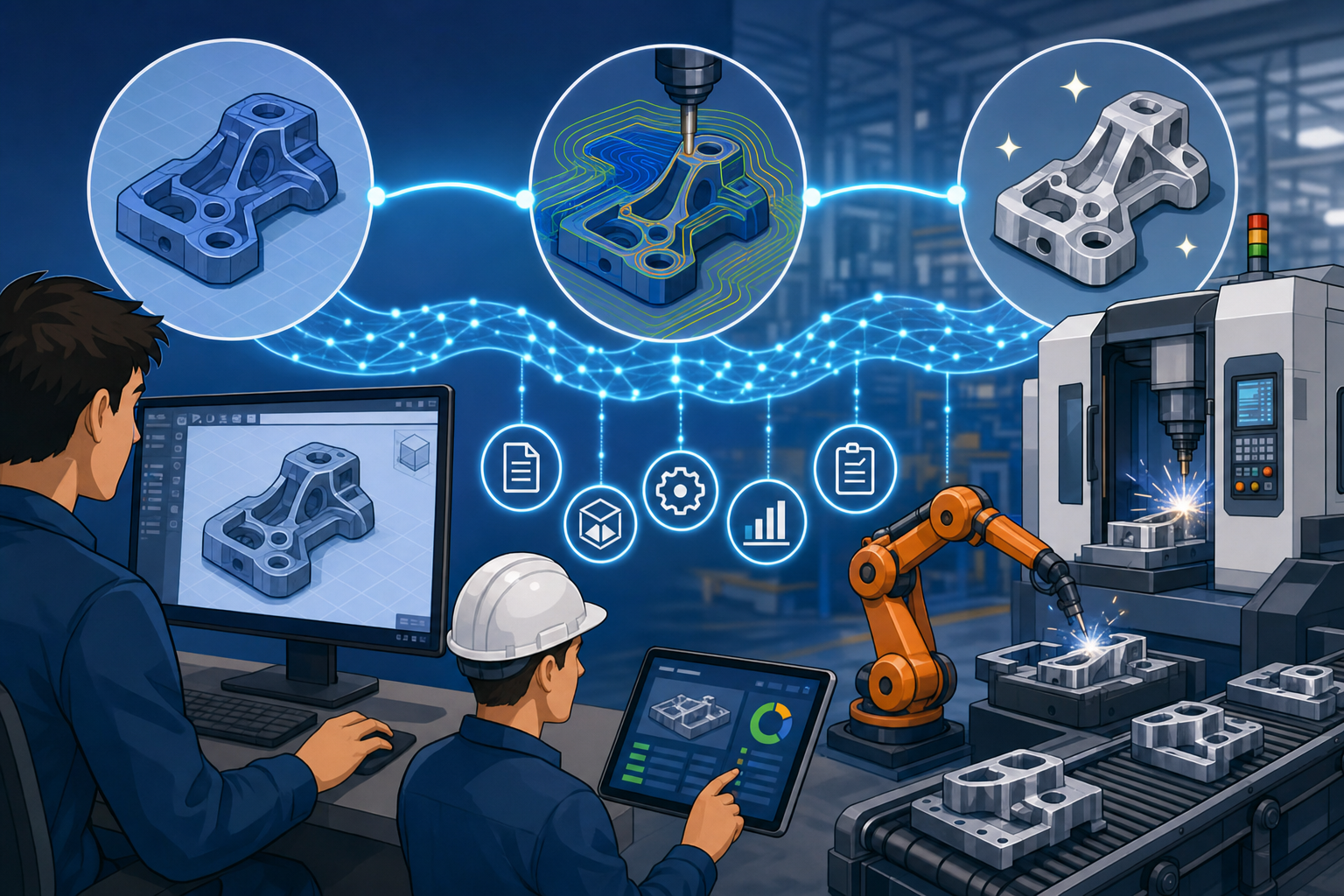


The move from CAD to CAM was not a simple software upgrade; it was a structural change in how engineering knowledge traveled through industry. The story begins with drawings, punched tapes, numerical control, aircraft geometry, machine tools, and the gradual realization that design information could become manufacturing instruction.
The Break Between Design and Manufacturing Before Integration
CAD And CAM Began As Different Industrial Languages
Before CAD and CAM were treated as parts of one connected workflow, they belonged to different professional worlds. CAD developed around drafting, geometry creation, standards-based documentation, dimensioning, and the formal communication of engineering intent. Its earliest value was not that it automatically manufactured anything, but that it accelerated and improved the creation of drawings that had previously been made by hand on boards with T-squares, vellum, ink, and later Mylar. Early CAD systems such as Ivan Sutherland’s Sketchpad at MIT in 1963 demonstrated interactive graphical design, but industrial adoption initially centered on producing precise engineering documentation and reusable geometry. CAM, by contrast, grew from the needs of the machine shop. It was concerned with cutters, feeds, speeds, axes, machine limits, coordinate systems, punched tapes, and the practical question of how to move a tool through metal without destroying the part, the fixture, or the machine. In this early period, CAD described the object, while CAM described the actions required to make it, and the link between the two was often a human being reading a drawing and translating intent into process.
Numerical Control Came Before Modern CAD
One of the most important historical facts in CAD/CAM integration is that numerical control did not wait for mature CAD. NC machining emerged earlier, driven by aircraft manufacturing problems that were too complex, repetitive, and expensive to solve with purely manual methods. John T. Parsons, working with Frank Stulen at Parsons Corporation in Traverse City, Michigan, helped connect punched-card computation to the manufacture of helicopter rotor blades and aircraft structural parts in the late 1940s. Their work showed that numerical data could guide machine motion for complex contours. The U.S. Air Force then supported further development at MIT’s Servomechanisms Laboratory, where researchers including Gordon Brown and others helped create early numerically controlled machine tools in the 1950s. These systems used punched tape and servo-controlled axes to move cutters according to encoded instructions. The breakthrough was profound: manufacturing motion could be programmed. Yet the source geometry was not typically a rich digital CAD model. It was often derived from calculations, lofting data, tabulations, templates, and drawings. The machine could move digitally before the design office had a unified digital representation of the product.
The Drawing Remained The Contract
For decades, the engineering drawing remained the legal, technical, and organizational contract between design and manufacturing. A drawing contained dimensions, tolerances, notes, material specifications, surface finish requirements, revision history, and sometimes manufacturing hints, but it did not contain an executable process. The machinist, manufacturing engineer, tool designer, or NC programmer had to interpret the drawing and decide how to hold the part, which cutter to use, what surfaces mattered most, and how to sequence operations. This interpretation was skilled and often brilliant, but it also created ambiguity. A designer might intend a surface to be aerodynamically continuous, while a shop-floor process might approximate it through discrete passes or manual finishing. Complex curves and compound surfaces were especially difficult because drawings represented them indirectly through sections, coordinates, offsets, or loft lines. In aircraft and automotive work, the physical master model, loft template, or clay surface could carry as much authority as the drawing itself. The early digital thread therefore did not behave like a clean database pipeline; it was a fragile chain connecting paper, calculations, punched tape, proprietary machine formats, and expert judgment.
Proprietary Systems Made Transfer Difficult
Geometry transfer was difficult not only because design and manufacturing had different priorities, but because early computer systems were isolated islands. A company might use one system for drafting, another for surface definition, another for NC programming, and another for machine-specific post-processing. Data files were often proprietary, undocumented outside the vendor or internal development group, and optimized for the assumptions of one machine or workflow. Even when the same nominal geometry moved from design to manufacturing, the receiving system might interpret curves, units, tolerances, or surface boundaries differently. Machine tools also required controller-specific instructions, and early NC equipment from companies such as Cincinnati Milacron, Kearney & Trecker, Giddings & Lewis, and later FANUC-controlled systems demanded post-processing that reflected each controller’s language and mechanical behavior. The result was that the first practical forms of digital manufacturing information were heavily mediated. A punched tape might look digital, but it was only the final artifact of many translations. The modern idea of a seamless digital thread did not yet exist; industry had data fragments, each useful, each vulnerable to loss of meaning.
- CAD priority: accurate geometry, documentation, dimensions, revisions, and communication of design intent.
- CAM priority: tool motion, cutter compensation, machine constraints, fixturing, material removal, and shop execution.
- Early integration problem: drawings and tapes carried information, but people carried much of the meaning.
The Rise Of CAD/CAM Systems In Aerospace And Automotive
Why Aerospace And Automotive Led The Push
Aerospace and automotive companies became the first major industrial forces pushing CAD and CAM together because their geometry was expensive, subtle, and unforgiving. Aircraft skins, wing surfaces, fuselage sections, inlet ducts, propeller forms, turbine components, and structural members required shapes that could not be fully controlled by simple orthographic drawings. Automotive manufacturers faced similar problems with exterior body panels, dies, molds, glass openings, and interior surfaces where styling, aerodynamics, tooling, and assembly had to converge. A small error in surface definition could produce a costly tooling mistake, and a tooling mistake could affect thousands or millions of downstream parts. These industries also faced immense pressure to reduce physical prototypes. Full-scale aircraft mockups, automotive clay models, dies, and jigs required time, material, and specialized labor. Repeatability mattered because the same geometry needed to move from styling to engineering, from engineering to tooling, and from tooling to production. The promise of integrated CAD/CAM was not merely convenience. It was economic survival in industries where complex surfaces, large programs, and high capital costs made every translation error painfully expensive.
APT And The First Widely Influential CAM Language
MIT played a central role in the CAM side of the story through APT, the Automatically Programmed Tool language. Developed beginning in the 1950s with support from the U.S. Air Force and contributions from researchers such as Douglas T. Ross at MIT, APT became one of the foundational languages for describing tool motion in a more abstract and portable way than raw machine codes. Instead of writing every motion directly in a controller-specific format, programmers could define geometry and tool movements using higher-level statements, and then post-process those instructions for particular machines. This was a major step toward separating manufacturing logic from machine-specific execution. APT was not CAD in the modern parametric solid modeling sense, but it introduced an essential principle: a computer-readable description of geometry and process could be transformed into machine action. In aerospace, where complex contoured parts were common, this mattered greatly. APT helped standardize NC programming concepts and influenced generations of CAM systems. It also exposed a core challenge that still exists today: geometry alone is insufficient unless the manufacturing process can interpret it reliably and safely.
DAC-1 And Automotive Digital Geometry
General Motors and IBM advanced the design side of integration with DAC-1, the Design Augmented by Computer system, developed in the early 1960s. GM’s interest was not academic curiosity; it wanted ways to manage the overwhelming complexity of automotive development. Engineers and designers needed to visualize, modify, analyze, and communicate shapes more effectively than paper drawings allowed. DAC-1, associated with figures such as Dr. Patrick J. Hanratty, IBM engineers, and GM’s internal technology leadership, demonstrated how interactive computer graphics could support automotive engineering. Hanratty would later become one of the most influential figures in commercial CAD/CAM through Manufacturing and Consulting Services, whose ADAM system influenced many later products. DAC-1 helped establish that digital geometry could become a shared industrial asset, not merely a drafting output. Although early hardware was expensive and access was limited, the conceptual shift was decisive. Automotive companies began to see that body geometry, tooling geometry, and manufacturing preparation could all benefit from being connected in computation. The car body was no longer only a physical clay or a set of drawings; it was increasingly a mathematical object.
CATIA, Dassault, And Aircraft-Driven Integration
CATIA emerged from the manufacturing demands of aircraft design at Dassault Aviation. In the 1970s, Dassault engineers developed software initially connected to three-dimensional surface design and NC manufacturing needs, building on ideas and infrastructure related to CADAM, an IBM drafting system. Under the leadership of figures including Francis Bernard, who became a central figure in Dassault Systèmes, CATIA evolved into one of the most important CAD/CAM/CAE platforms in the world. Dassault Systèmes was created in 1981 to commercialize CATIA, with IBM serving as a major distribution partner. The significance of CATIA was that it grew from a world where design and manufacturing could not be separated cleanly. Aircraft geometry had to support aerodynamic performance, structural design, tooling, inspection, and final assembly. CATIA’s strength in complex surfacing made it especially valuable for aerospace and later automotive industries. It helped establish the idea that the same geometric foundation could serve multiple downstream purposes. In this environment, the digital model began to replace fragmented intermediaries, and manufacturing preparation increasingly depended on the authority of controlled digital geometry.
Unigraphics And The Industrial CAD/CAM Platform
Unigraphics followed another important path toward integrated CAD/CAM. Its roots are connected to United Computing and the UNIAPT system, and it later became closely associated with McDonnell Douglas, which acquired United Computing in the mid-1970s. McDonnell Douglas had deep aerospace manufacturing needs, and Unigraphics developed into a platform that combined design, drafting, machining, and later solid modeling capabilities. The system passed through major corporate chapters involving McDonnell Douglas Automation, EDS, UGS, and eventually Siemens, where it became part of NX. Unigraphics mattered because it treated CAD/CAM not as a loose coupling of drafting and NC utilities, but as a manufacturing-aware engineering environment. In aerospace and machinery, users needed to design parts and then create reliable toolpaths from the same controlled geometry. Over time, Unigraphics/NX became known for deep integration across modeling, assemblies, machining, simulation, and product data management. This path reflected a broader industry lesson: the more complex the product, the more dangerous it became to treat design data as a static drawing. Companies needed a living model that could support machining, tooling, verification, and revision control.
Surface Modeling Turned Visual Form Into Manufacturable Geometry
Surface modeling was central to the rise of CAD/CAM because many important industrial shapes are not defined by simple planes, cylinders, and cones. Aircraft skins, turbine blades, intake ducts, injection molds, stamping dies, and automotive body panels require smooth mathematical control over curvature, tangency, continuity, and transition behavior. The development and industrial adoption of Bézier curves, B-splines, NURBS, and related spline methods changed what CAD systems could represent. Pierre Bézier at Renault and Paul de Casteljau at Citroën independently made crucial contributions to curve and surface mathematics in the automotive context, showing how complex forms could be controlled computationally. These methods gave designers and engineers a way to describe surfaces that were both visually refined and numerically precise. For CAM, this precision was transformative. A surface could be sampled, offset, intersected, and followed by a cutter path. Tooling for body panels or aircraft forms could be machined from the same mathematical description used by engineering. CAD was therefore no longer just replacing the drafting board. It was beginning to drive machines directly through mathematically controlled geometry.
- APT gave NC programming a higher-level language for tool motion and geometry references.
- DAC-1 demonstrated the industrial value of interactive automotive digital geometry.
- CATIA grew from aircraft design and manufacturing pressure for complex surfaces.
- Unigraphics helped establish integrated CAD/CAM as a production engineering platform.
Toolpaths, Kernels, And The Making Of A Manufacturing Model
A Design Model Is Not Yet A Manufacturing Model
The distinction between a design model and a manufacturing model is one of the most important concepts in CAD/CAM history. A CAD model describes the desired part: its nominal shape, dimensions, features, assemblies, and design intent. A CAM model must describe how that part will be made from stock material under real process constraints. It must account for cutter diameter, tool length, corner radius, holder geometry, spindle speed, feed rate, machine axes, fixture location, work coordinate systems, tolerances, remaining material, and safe approach and retract moves. A perfect CAD model may still be impossible or impractical to machine in one setup. It may require roughing, semi-finishing, finishing, drilling, tapping, turning, indexing, inspection, and deburring. The CAM system therefore transforms ideal geometry into a process plan. This transformation is where the digital thread becomes operational. Manufacturing software must ask questions that design software may not answer directly: Where is the stock? What material remains after each operation? Can the tool reach the surface? Will the holder collide? Is the tolerance achievable at the programmed feed and machine condition?
Toolpath Generation Became The Heart Of CAM
Toolpath generation is the practical core of CAM, and its development shaped the architecture of CAD/CAM software. Milling operations require strategies for roughing, contouring, pocketing, rest machining, finishing, scallop control, and high-speed machining. Turning requires tool motion around rotational geometry, management of inserts, grooves, threads, and parting operations. Drilling requires hole recognition, cycle selection, pecking behavior, and efficient ordering. Multi-axis machining adds even greater complexity because the tool orientation changes while the cutter moves, allowing access to undercuts, impellers, turbine blades, and complex molds, but also increasing the risk of collision and overtravel. CAM algorithms must convert surfaces and solids into motion that removes material efficiently while preserving the desired geometry. This involves offsets, intersections, stepovers, cusp height calculations, smoothing, lead-in and lead-out construction, and machine-aware motion control. Historically, systems that could generate reliable toolpaths from CAD geometry became indispensable because they reduced dependence on manual NC programming. The machine shop was no longer merely receiving drawings; it was receiving computed motion derived from controlled geometry.
Collision Detection And Post-Processing Made Geometry Machine-Specific
Collision detection and post-processing are where the idealism of digital geometry meets the reality of machines. A cutter does not exist as a mathematical point; it has a body, flutes, shank, holder, spindle nose, and limitations. Fixtures, clamps, vises, tombstones, rotary tables, and neighboring part features create hazards that must be checked. The CAM system must determine whether the tool, holder, or machine component will intersect the part or setup during motion. This requirement became especially important with five-axis machining, where rotary axes introduce non-intuitive movements. Post-processing then converts CAM toolpaths into controller-specific NC code. A program for a FANUC controller may differ from one for Siemens SINUMERIK, Heidenhain, Mazak Mazatrol, Okuma OSP, or Haas controls. The postprocessor must understand coordinate transformations, canned cycles, rotary axis behavior, inverse time feed, cutter compensation, machine limits, and preferred shop conventions. This is why CAD/CAM integration never meant that one mathematical model could ignore the factory. Instead, the model had to flow through manufacturing intelligence that translated design intent into safe, efficient, controller-specific execution.
Geometric Modeling Kernels Standardized The Calculations
Geometric modeling kernels gave CAD/CAM software a stronger computational foundation. Early wireframe systems could represent edges and curves, but they struggled to support robust manufacturing calculations because they did not fully define volume or topology. Boundary representation, or B-rep, and solid modeling made it possible to calculate faces, edges, vertices, intersections, offsets, Boolean operations, mass properties, and material removal with far greater reliability. Kernels such as Parasolid, developed by Shape Data and later owned by Siemens, and ACIS, developed by Spatial Technology and associated with figures such as Dick Sowar and others in the solid modeling community, became widely used foundations for CAD and CAM applications. They allowed software developers to build on standardized geometric operations rather than inventing every low-level calculation from scratch. For CAM, this mattered because machining depends on questions of contact, containment, removal, and accessibility. To generate a toolpath, the system must know where surfaces are, how they intersect, where boundaries lie, and how offsets behave. Solid modeling turned geometry from a picture into computable manufacturing structure.
Major Platforms Expanded The Manufacturing Model
Many software companies contributed to the evolution from separate CAD and CAM tools into increasingly integrated manufacturing environments. UG/NX, CATIA, Mastercam, GibbsCAM, PowerMILL, Cimatron, Esprit, and later systems from Autodesk, Siemens, and Dassault Systèmes each shaped different parts of the market. Mastercam, developed by CNC Software beginning in the 1980s, became especially influential among machine shops because it provided accessible programming for milling, turning, and wire EDM. GibbsCAM, from Gibbs and Associates, earned a reputation for production-oriented CNC programming, particularly in turning and mill-turn environments. PowerMILL, developed by Delcam in the United Kingdom before Autodesk acquired Delcam in 2014, became prominent in high-speed machining and complex mold and die work. Cimatron served toolmaking, mold, die, and manufacturing engineering workflows. Esprit, developed by DP Technology and later acquired by Hexagon, focused on advanced CNC programming including multi-axis and mill-turn machines. These systems proved that CAM was not an accessory to CAD. It was a specialized computational discipline that forced design geometry to become operational, manufacturable, verified, and machine-aware.
The Manufacturing Model Became A Process Container
As CAD/CAM matured, the manufacturing model began to contain far more than geometry and toolpaths. It increasingly included stock definitions, setup sheets, tooling libraries, machine simulation, process templates, feature recognition, tolerance requirements, inspection plans, and links to product data management. Feature-based machining, promoted in different forms by companies such as Siemens, Dassault Systèmes, PTC, Autodesk, and specialized CAM vendors, attempted to recognize holes, pockets, slots, bosses, and planar regions as manufacturing features rather than anonymous surfaces. This allowed automation of repetitive programming decisions and helped standardize shop practices. Knowledge-based machining extended the idea by capturing preferred tools, feeds, speeds, strategies, and rules for particular materials or machines. The CAM model therefore became a process container: a structured representation of how a product would be made, not merely what it looked like. This is the point at which CAD/CAM integration became strategically important. Once manufacturing knowledge attaches to the model, design changes can be evaluated not only for fit and function, but also for cost, cycle time, tool access, and production risk.
- Design model: nominal product definition, geometry, features, dimensions, and engineering intent.
- Manufacturing model: stock, fixtures, tools, operations, tolerances, machine kinematics, and process sequence.
- Kernel contribution: reliable calculations for surfaces, solids, offsets, intersections, and material removal.
- CAM contribution: conversion of descriptive geometry into executable industrial motion.
The Digital Thread Becomes An Industrial Philosophy
From Geometry Transfer To Manufacturing Intelligence
The historical shift from CAD to CAM integration turned design data into manufacturing intelligence. At first, companies wanted a better way to transfer shapes from engineering to production. Over time, they discovered that transfer was too narrow a goal. What industry actually needed was continuity of meaning: geometry, tolerances, materials, revisions, tooling decisions, simulation results, inspection plans, and manufacturing feedback had to remain connected as the product evolved. This broader continuity became known as the digital thread. The term describes more than file exchange. It describes a philosophy in which product information flows across design, analysis, process planning, machining, assembly, inspection, service, and lifecycle management without repeatedly losing context. The early chain of drawings, punched tapes, proprietary files, and human interpretation gradually evolved into managed product data environments. The model became an authority not only for shape, but for decisions. This was the long-term consequence of CAD/CAM integration: once manufacturing began to depend directly on the digital model, the entire enterprise had a reason to protect, manage, validate, and enrich that model.
PLM Extended The Thread Across The Enterprise
Product lifecycle management systems expanded the digital thread beyond the engineering workstation and the CAM programming office. Siemens Teamcenter, Dassault Systèmes ENOVIA, and PTC Windchill became major platforms for managing product structures, revisions, configurations, workflows, approvals, requirements, documents, and links between design and manufacturing information. Their importance grew because CAD/CAM integration created a new problem: if the model drives manufacturing, then the organization must know which model is authoritative. A wrong revision can produce scrap, rework, contractual failure, or safety risk. PLM systems helped coordinate the release process, engineering change orders, manufacturing bills of material, supplier collaboration, and traceability. This changed the social structure of engineering work. The digital model was no longer a private file owned by one designer or programmer; it became an enterprise asset. Teamcenter’s connection to NX, ENOVIA’s connection to CATIA and the broader 3DEXPERIENCE platform, and Windchill’s connection to PTC Creo illustrate how vendors built ecosystems around controlled product information. The digital thread became a management system as much as a modeling system.
Model-Based Definition Reduced Dependence On Drawings
Model-based definition, or MBD, pushed the CAD/CAM story further by embedding product manufacturing information directly in the 3D model. Instead of treating the two-dimensional drawing as the primary authority, MBD allows dimensions, tolerances, datums, surface finishes, notes, and inspection requirements to be associated with the model itself. This development addressed one of the oldest problems in the CAD-to-CAM journey: drawings carried critical meaning, but they also required reinterpretation. With MBD, a manufacturing system, inspection system, or downstream application can theoretically read semantic information directly from the model. Standards such as ASME Y14.41 and ISO 16792 helped formalize this transition. The implications are significant for CNC machining, additive manufacturing, coordinate measuring machines, and quality planning. A hole is not just a cylinder; it may carry positional tolerance, finish requirements, thread specifications, and datum relationships. When this information is machine-readable, automated manufacturing planning and inspection become more realistic. MBD did not eliminate drawings everywhere, but it shifted authority toward the model. It expressed a mature form of the original CAD/CAM ambition: fewer translations, fewer ambiguities, and faster propagation of engineering change.
Additive Manufacturing And Digital Twins Expanded The Meaning
Additive manufacturing expanded the digital thread beyond subtractive CNC machining by making the relationship between model and process even more direct. In powder bed fusion, directed energy deposition, binder jetting, material extrusion, and photopolymer processes, the model is sliced into layers and transformed into build instructions. Yet additive manufacturing also reveals why geometry alone is never enough. Build orientation, support structures, thermal distortion, residual stress, scan strategy, powder behavior, post-processing, and inspection all affect whether the final part matches intent. Companies such as 3D Systems, Stratasys, EOS, GE Additive, Materialise, Autodesk, Siemens, and Dassault Systèmes developed tools that connect design, simulation, build preparation, and validation. Digital twins pushed the idea further by linking virtual product and process models to operational data from machines, sensors, and inspection systems. The manufacturing model became something that could learn from production. Closed-loop inspection, using coordinate measuring machines, laser scanners, machine probing, and metrology software from companies such as Hexagon, Zeiss, Renishaw, and FARO, allowed measured results to feed back into process correction and design improvement.
The Final Meaning Of CAD-To-CAM Integration
The history of CAD-to-CAM integration is the history of engineering information becoming executable. In the beginning, CAD and CAM were separate because design and manufacturing were organized around different artifacts, different skills, and different technologies. Design produced drawings and geometric definitions; manufacturing produced toolpaths, fixtures, tapes, and parts. Aerospace and automotive companies forced these worlds together because complex surfaces, high tooling costs, repeatability demands, and prototype reduction made separation too expensive. APT, DAC-1, CATIA, Unigraphics, and later platforms such as NX, Mastercam, PowerMILL, Cimatron, GibbsCAM, Esprit, Creo, and integrated Autodesk tools each contributed to a larger transformation. Geometric kernels made models computable. CAM algorithms made tool motion reliable. PLM systems made product information governable. MBD, additive manufacturing, digital twins, and closed-loop inspection extended the thread into new processes. The central lesson is clear: the model stopped being only a representation of a product and became part of the process that made the product real. The digital thread took shape when geometry became decision-making, and decision-making became machine action.
Also in Design News