Your Cart is Empty
Customer Testimonials
-
"Great customer service. The folks at Novedge were super helpful in navigating a somewhat complicated order including software upgrades and serial numbers in various stages of inactivity. They were friendly and helpful throughout the process.."
Ruben Ruckmark
"Quick & very helpful. We have been using Novedge for years and are very happy with their quick service when we need to make a purchase and excellent support resolving any issues."
Will Woodson
"Scott is the best. He reminds me about subscriptions dates, guides me in the correct direction for updates. He always responds promptly to me. He is literally the reason I continue to work with Novedge and will do so in the future."
Edward Mchugh
"Calvin Lok is “the man”. After my purchase of Sketchup 2021, he called me and provided step-by-step instructions to ease me through difficulties I was having with the setup of my new software."
Mike Borzage
Create a 3D Model using BricsCAD: A Step-By-Step Guide
November 02, 2023 2 min read

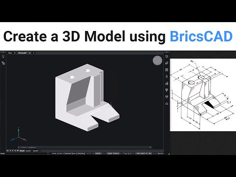
Welcome to a comprehensive tutorial where we will delve into the world of 3D modeling using BricsCAD. In this video guide, we will break down the process of creating a 3D model step by step. By the end of this tutorial, you'll not only have a 3D model of an object but also gain familiarity with fundamental solid modeling operations and the application of UCS (User Coordinate System) in BricsCAD. So, let's embark on this creative journey and create a 3D model that will sharpen your skills and unleash your modeling potential.
Step 1: Setting the Stage
To begin, let's align our view with the 'top, front, left' perspective to match the model in our drawing. Click on the 'top front left face' in the 'look from widget' to adjust your view.
Step 2: Creating the Base Profile
The foundation of our model is a specific profile. Using the UCS, we'll align it with the left face. Access the UCS settings by clicking on the 'view' tab, then navigate to the 'coordinates' option and choose 'UCS'. Align the UCS with the left face. With the UCS set, we can move on to create construction lines that form our profile. The dimensions are provided, so you can use the 'line' command and 'offset' command to craft this intricate base profile.
Step 3: Extruding the Base Profile
With the profile in place, we will extrude it to add depth and dimension to our model. Select the profile, right-click, and choose 'extrude'. Extend it downwards in the negative z-axis direction with an extrusion height of 60 units. The profile is now a solid.
Step 4: Adding Components
To make our model more complex, we'll add components. These components can be created using the 'polyline' command and 'extrude' command. Each component is crafted separately and then positioned accurately using distance measurements. You'll learn how to manipulate and position these elements effectively.
Step 5: Combining Components.
The 'union' command comes to play as we combine the separate components into a single unit. This is essential to create a cohesive model where the components interact seamlessly.
Step 6: Creating Holes and Slots
In our final steps, we introduce holes and slots into the model. To align with these features, the UCS is adjusted to specific faces as needed. We create circles, extrude them to form holes, and use the 'subtract' command to remove them from the main solid. Additionally, you'll learn how to align UCS with slant faces and create intricate slots.
Also in Design News

Revit Tip: Standardize Annotation Crops and Borders with View Templates
January 23, 2026 2 min read
Read More
V-Ray Tip: Reuse Single Light Cache Prepass for Camera-Only Animation
January 23, 2026 2 min read
Read MoreSubscribe
Sign up to get the latest on sales, new releases and more …


