Your Cart is Empty
Customer Testimonials
-
"Great customer service. The folks at Novedge were super helpful in navigating a somewhat complicated order including software upgrades and serial numbers in various stages of inactivity. They were friendly and helpful throughout the process.."
Ruben Ruckmark
"Quick & very helpful. We have been using Novedge for years and are very happy with their quick service when we need to make a purchase and excellent support resolving any issues."
Will Woodson
"Scott is the best. He reminds me about subscriptions dates, guides me in the correct direction for updates. He always responds promptly to me. He is literally the reason I continue to work with Novedge and will do so in the future."
Edward Mchugh
"Calvin Lok is “the man”. After my purchase of Sketchup 2021, he called me and provided step-by-step instructions to ease me through difficulties I was having with the setup of my new software."
Mike Borzage
An In-Depth Guide to 3D Modeling with BricsCAD
October 02, 2023 2 min read


An In-Depth Guide to 3D Modeling with BricsCAD
BricsCAD is a powerful, intuitive, and interoperable CAD and modeling tool from Bricsys that offers cutting-edge solutions for designers, innovators, and engineers. It is known for its high-performing, compatible, and concise 2D drafting and detailing, along with its robust 2D/3D CAD modeling. This guide will delve into the process of creating a 3D model in BricsCAD.
Creating a 3D Solid in BricsCAD
3D modeling in BricsCAD involves a series of steps starting with defining the object's profile, aligning the User Coordinate System (UCS), and creating construction lines. Offsetting these lines, creating a 3D profile, and extruding the profile are the next steps. After the profile has been extruded, the construction lines can be deleted.
Other components are created similarly by creating a profile and using the EXTRUDE command. These components are then moved into position using the Move command. Components can then be combined into a single unit using the UNION command.
Adding Details to the Model
To add details to a model, such as creating holes or cutting slots, you will need to align the UCS to the relevant face. The CIRCLE command and the EXTRUDE command can be used to create holes. Slots are created by aligning the UCS on the slanted face, drawing lines, and extruding the profile.
Once all these steps are done, you can combine all the elements into a final 3D model. The SUBTRACT command can be used to subtract the circles and the slot from the main solid, resulting in the final 3D model.
Visual Styles
Visual styles in BricsCAD control the display of 3D solids and surfaces. They help in adding the finishing touches to your designs by controlling aspects such as edge visibility, lighting, and material shading. BricsCAD offers several visual styles to choose from, allowing for a wide range of visual effects.
Conclusion
BricsCAD stands out for its user-friendly interface, powerful 3D modeling capabilities, and seamless interoperability with other CAD software. Its toolset and workflows are familiar and intuitive, making it easy even for beginners to start creating complex 3D models.
For more information about the newest and most advanced design software technology, including BricsCAD, contact our sales team at NOVEDGE. We offer a wide range of design software solutions that are compatible with BricsCAD, such as Autodesk products, V-Ray, and many more. Our experts are always ready to guide you in selecting the best software for your needs.
Also in Design News

Embracing Data-Driven Design: Revolutionizing Product Development with Advanced Analytics
October 02, 2025 12 min read
Read More
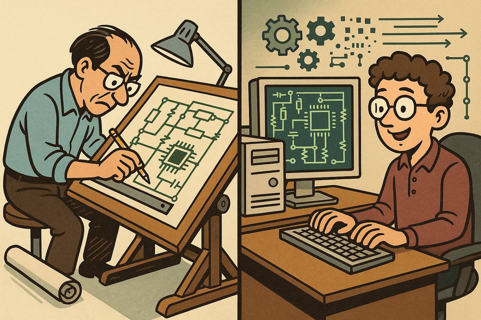
Design Software History: Early Electronics CAD: From Manual Drafting to Algorithm-Driven Design and Its Impact on the Industry
October 02, 2025 10 min read
Read More
Cinema 4D Tip: Streamline Scene Management in Cinema 4D with the Stage Object
October 02, 2025 3 min read
Read MoreSubscribe
Sign up to get the latest on sales, new releases and more …


