Your Cart is Empty
SketchUp to BIM: 5 Upstream Modeling Habits That Speed Revit/Archicad/IFC Handoffs
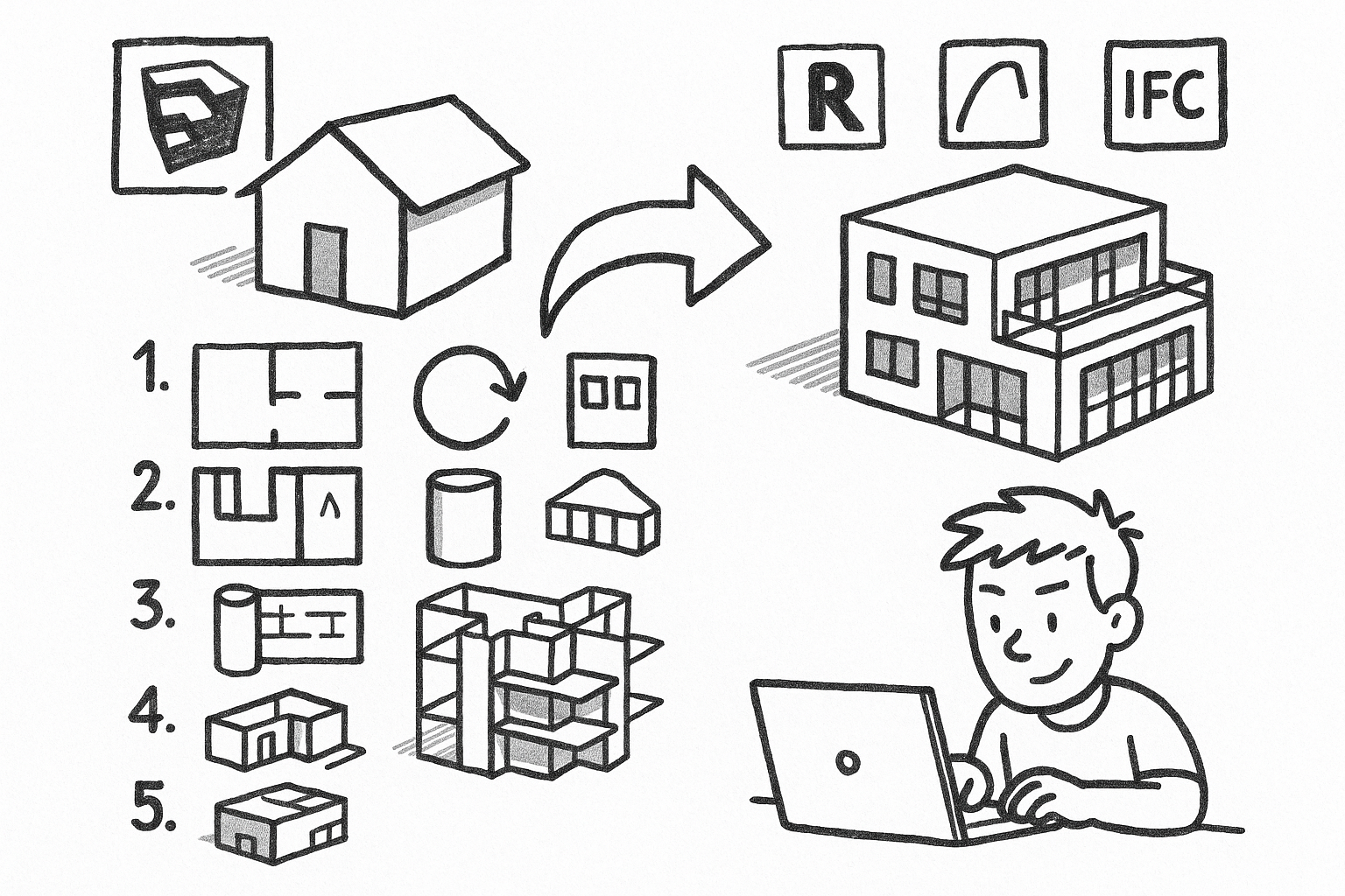


Designers who model early in SketchUp can dramatically accelerate downstream BIM authoring and documentation by adopting a handful of upstream habits. The promise is simple: faster BIM conversion, cleaner drawings, and fewer rebuilds when moving from SketchUp to Revit, Archicad, or IFC-based workflows. If you regularly hand off models for BIM, detailing, energy analysis, quantity takeoffs, or visualization, the smallest disciplines pay outsized dividends. The core idea is that small, disciplined modeling habits upstream prevent compounding errors—bad geometry, inconsistent naming, and missing intent—from ever reaching your BIM team.
Model with BIM intent, not just visual intent
Visual fidelity alone is not enough when your model is a precursor to a full BIM. Think of every element you create as a future wall, slab, roof, opening, or system—even if it begins as a schematic mass. This doesn’t mean over-modeling or prematurely detailing every layer; it means modeling with a clear, mappable intent so downstream tools can recognize, classify, and reconstruct building logic with minimal guesswork.
When you treat SketchUp geometry as “stand-ins” for real assemblies, you retain clarity of purpose: walls remain walls (not merged meshes), floor plates remain slabs (not paper-thin surfaces), and roofs are roofs (not sculpted solids with ambiguous edges). This approach keeps your conceptual speed while setting up reliable handoffs.
Habit checklist
- Keep elements conceptually separable: walls as walls, slabs as slabs, roofs as roofs—avoid single-mesh buildings.
- Avoid decorative modeling that fakes thickness or assemblies that should be explicit when needed for coordination.
- Prefer planar, orthogonal primitives when the real-world geometry is planar/orthogonal—avoid unnecessary micro-facets.
Downstream pain prevented
- Failed or unreliable wall/face recognition in BIM tools.
- Incorrect takeoffs when forms are sculpted instead of logically assembled.
- Rework when the BIM team needs to re-author elements to match real assemblies.
Practical patterns
- Use a “mass + systems” progression: start with clean massing (simple solids), then author major assemblies (walls, slabs, roofs), then secondary features (openings, stairs, rails).
- Maintain consistent thickness logic: exterior walls and slabs modeled to realistic, uniform thicknesses rather than inferred by offset surfaces.
Example: For a three-story office, begin with a rectilinear mass aligned to project axes. Extract floor plates as discrete slab solids with accurate thickness. Wrap mass faces with wall objects of true thickness, ensuring clean intersections at corners. Place roof volumes as separate solids with clear overhangs. When doors and windows come later, carve precise openings rather than erasing faces, retaining clean manifold solids. This sequence produces geometry that BIM applications can translate into wall and slab systems with predictable joins and materials.
Resist the urge to “detail with textures” where geometry is required for coordination. For instance, if exterior cladding depth matters for daylighting or facade coordination, model that thickness explicitly at the schematic level where appropriate. Thin, purely visual skins can mislead daylight simulations and facade quantities. Conversely, avoid over-modeling interior layering when it won’t affect early-stage decisions; model just enough for your intended downstream analyses and add detail progressively.
Enforce strict grouping, componentization, and instance logic
Instance discipline is the backbone of scalable models. The guiding principle is simple: if it repeats, it’s a component; if it’s unique, it’s a group; if it’s a boundary, it’s isolated. This ensures repetition stays editable, unique items remain manageable, and boundaries keep geometry from bleeding across logical objects.
Without this structure, edits become brittle: changes don’t propagate (or propagate where they shouldn’t), exports break due to non-manifold merges, and BIM family creation becomes manual rework. With it, your team can rapidly map components to BIM families, schedule instances, and maintain predictable visibility.
Habit checklist
- Never leave raw geometry loose at the model root—everything belongs to a group or component.
- Use components for:
- Repeating items such as windows, doors, mullions, furniture, fixtures, and facade modules.
- Families of similar objects, with the definition representing a type and variants created intentionally.
- Use groups for:
- One-off context shells, terrain, unique sculptural pieces, and building cores that won’t repeat.
- Keep nesting purposeful. Avoid deep nesting that obscures selection and export mapping; aim for two to three levels max where possible.
Downstream pain prevented
- Geometry bleeding or sticking faces that produce non-manifold solids and break IFC/Revit imports.
- Unmanageable BIM family creation because repeated parts aren’t consistently instanced.
- Update chaos when a change should propagate but doesn’t—or propagates across the wrong scope.
Documentation impact
- Consistent instance naming enables door/window schedules and type-driven documentation later.
- Cleaner section/elevation outputs when objects remain discrete and selectable for view filters.
Example: Treat all windows of a given type as the same component definition (e.g., “A-WIN-FIX_Type02”). Variants receive deliberate type definitions (“A-WIN-FIX_Type03”) rather than ad hoc scale edits. Mullions in curtain walls become components nested one level under a parent panel, enabling whole-façade updates by editing a single mullion definition. Unique lobby glazing geometry remains grouped, not componentized, to avoid unintended propagation. This simple discipline can trim hours from every iteration and enables type-driven schedules in the BIM environment.
For complex assemblies—say, a repeating bathroom pod—wrap the entire pod as a component, and subcomponentize the fixtures and cabinets. This allows the BIM team to map pods to families while still extracting individual fixtures when needed. Avoid nesting beyond three levels; deep hierarchies make selection, tagging, and export category mapping unnecessarily difficult.
Build a predictable naming, tagging, and classification system early
Metadata is design intent made legible to other software and other humans. A predictable naming convention, tag strategy, and classification layer transforms your SketchUp model into a source of truth that Revit, Archicad, and IFC importers can interpret reliably. The goal is not heavyweight BIM metadata at concept stage; it’s lightweight consistency that can be enriched downstream without remapping chaos.
Habit checklist
- Names
- Adopt a consistent convention for groups/components, such as discipline-category-type (e.g., A-WALL-EXT_Type01, A-DOOR-SGL_Type03).
- Differentiated type vs instance: the definition name expresses type; add an instance-level label only when needed (e.g., “Door 101” on a component instance).
- Tags (layers)
- Tags control visibility, not containment. Tag the container (group/component), not raw faces and edges.
- Align tag sets to downstream disciplines: Architectural, Structural, MEP, FF&E, Context, Presentation.
- Use a small, stable tag vocabulary early; expand cautiously as the model matures.
- Classification
- Apply IFC classification (or a parallel internal schema) to major categories: walls, slabs, roofs, openings, stairs, railings, columns, beams.
- Reserve a “To Classify” tag for items pending categorization to ensure nothing slips through untyped.
Downstream pain prevented
- Manual remapping during BIM import due to ambiguous or mixed categories.
- Broken visibility control in documentation views due to inconsistent tag use.
- Quantity takeoffs and filtering failures when objects aren’t reliably queryable.
Export and hand-off advantages
- More predictable mapping of elements to Revit/Archicad categories and IFC classes.
- Faster creation of BIM families and types from consistent component definitions and definitions aligned to discipline tags.
Example: Use Architectural tags like A-Wall, A-Slab, A-Roof, A-Openings; Structural tags like S-Column, S-Beam; MEP tags like M-Equipment, M-Duct, M-Pipe. Keep entourage under P-Entourage and context under X-Context. Apply IFC classifications such as IfcWall, IfcSlab, IfcRoof, IfcDoor, IfcWindow at the group/component level. For doors, define types using a standard pattern (e.g., A-DOOR-SGL_Type01 for 900x2100 single swing). Instances receive instance labels only when necessary for coordination (e.g., Door 101). This setup enables export mappers to route doors into Revit Doors category with minimal intervention.
When teams use a shared, lightweight naming and tagging reference, designers gain the freedom to iterate quickly without abandoning predictable classification. The BIM team can trust that visibility filters and category mapping will behave, schedules won’t drop items, and consultants can query the model for the right objects at the right time.
Control geometric cleanliness: axis alignment, tolerance discipline, and solid validity
Small geometric sloppiness causes disproportionately large failures downstream—especially in IFC exchanges, boolean operations, section cuts, energy models, and schedules. Clean geometry keeps your model efficient to navigate and makes it machine-readable. Think of it as computational hygiene: align axes, model to real dimensions, and maintain valid solids where solids are intended.
Habit checklist
- Axis and scale discipline
- Model near the origin and keep the building aligned to primary axes when possible to avoid floating-point artifacts.
- Use real units and enforce consistent precision; avoid “almost” dimensions like 2999.7 mm where 3000 mm is intended.
- Face/edge hygiene
- Eliminate stray edges, internal faces, coplanar overlaps, and z-fighting surfaces—especially at corners and openings.
- Cut openings properly; avoid leaving floating voids that aren’t actually subtracting from solids.
- Solids and manifold geometry
- Validate that groups/components intended as volumetric are true solids with closed volumes.
- Avoid non-manifold edges and zero-thickness slivers that break boolean operations and mesh exports.
Downstream pain prevented
- IFC exports producing fragmented elements or missing faces due to non-manifold meshes.
- Section/elevation artifacts in documentation—fuzzy lines, gaps, doubled edges.
- Failed energy/structural analyses caused by leaky volumes and invalid solids.
Recommended checks
- Run periodic cleanup passes at milestones—concept freeze, design development, pre-export—and fix flagged solids and edges.
- Simplify over-modeled curved geometry; reduce segments when curvature isn’t architecturally meaningful or when it hinders clean booleans.
Example: Before exporting a facade with curved profiles, reduce arc segmentation to a sensible count so downstream triangulation doesn’t explode file size or break boolean subtractions. For floor plates, ensure slab solids are genuinely closed volumes; a single missing face at a stair opening can cause an energy model to treat the entire story as outdoors. Align the project to the world axes at model start, and resist rotating the entire building late in the process; instead, create scenes for rotated presentation views while keeping the modeling axes stable for production.
Adopt tolerances that match downstream expectations. If structural grids and walls are intended to align to 1 mm or 1/16 in increments, model them that way. When snapping, avoid inferencing to off-axis geometry unless that deviation is intentional. Use guides and temporary sections to ensure openings are square and consistent. The result is a model that behaves predictably in booleans, cuts clean sections, and exports to IFC without a trail of broken edges and missing faces.
Structure the model for handoff: levels, scenes, and export-ready views
A model is only handoff-ready when it communicates scope, states, and clean extraction paths. Export-ready views, level logic, and explicit separation of presentation assets from production geometry prevent confusion and give downstream teams exactly what they need without manual detective work.
Habit checklist
- Levels and reference planes
- Establish consistent floor-to-floor logic and keep floor plates and major datums explicit and aligned.
- Use guides and section cuts to lock critical heights for sills, head heights, parapets, and ceiling planes.
- Scenes as documentation and coordination states
- Create standardized scenes: plans per level, key sections, elevations, reflected ceiling intent, and coordination views.
- Save style and visibility states with each scene so exports are repeatable rather than manual toggles.
- Separate presentation from production
- Isolate entourage, proxies, and visualization assets—ideally in separate files or clearly tagged containers.
- Organize schematic options in dedicated containers or separate models rather than hidden-geometry clutter.
Downstream pain prevented
- Ambiguity about what is real versus visualization-only geometry.
- Inconsistent exports causing delta errors between iterations.
- BIM teams spending time deciphering design states instead of modeling.
Handoff packaging
- Provide an export matrix listing what goes out as IFC, DWG, and SKP by discipline and by scene, with units and coordinate notes.
- Include a simple “model README” describing naming schema, tag system, level logic, units, classification approach, and known limitations.
Example: For a mid-rise, define level scenes L01–L12 with only production geometry visible (A-Wall, A-Slab, A-Roof, A-Openings, S-Column, S-Beam, M-Equipment). Keep context and entourage under X-Context and P-Entourage, off by default for production scenes. Establish coordination scenes such as “Envelope_Coord,” “Structure_Coord,” and “MEP_Clearances,” each with tailored visibility and styles for clash review. For presentation, duplicate scenes into a “Viz” group with stylized edges, textures, and lighting—but keep those assets isolated so a BIM export doesn’t accidentally include trees and cars.
Ensure that section and elevation scenes are locked to the same view properties each time: cut depths, styles, and visible tags. When exporting to IFC, DWG, or native BIM formats, reference the export matrix so each scene corresponds to a known, repeatable output. This eliminates guesswork and builds trust across disciplines: the same scene always produces the same content with each iteration.
Putting it all together for downstream acceleration
When you combine BIM intent, instance discipline, consistent metadata, geometric cleanliness, and handoff structure, your SketchUp model becomes a reliable staging ground for the entire project. The BIM team will spend less time fixing geometry and more time enriching it with parameters, materials, and details. Estimators can query consistent components for takeoffs. Sustainability consultants can run early analyses against closed volumes. Visualization teams can swap presentation assets without contaminating production geometry. Most importantly, design changes propagate where intended, reliably and quickly.
Think of this as establishing an upstream contract. You’re promising downstream consumers that walls are walls, not ambiguous meshes; that repeating systems are truly repeated; that names, tags, and classifications are predictable; that solids are valid; and that scenes correspond to coordinated outputs. Every habit dramatically reduces friction in Revit/Archicad/IFC pipelines, where category mapping, boolean operations, and schedule queries are often the first to fail under sloppy modeling.
Teams that adopt these practices often report meaningful reductions in handoff time and rework. More crucially, design fidelity improves because intent is preserved across tools. A clean wall object with correct thickness and classification moves downstream as a wall, receives appropriate materials and joins, appears correctly in sections, and can be scheduled with confidence. A window component that’s consistently instanced across a facade becomes a managed BIM family, not twenty unique fragments. A structured set of scenes becomes a portable publication system for exports, with less risk of accidental omissions or inadvertent inclusions.
Common pitfalls and how to avoid them
Even experienced modelers fall into patterns that slow down BIM conversion. A few watchouts can keep your process aligned with the intent of downstream authoring:
- Over-nesting components: Simplify hierarchies so selection, tagging, and export mappers can work reliably.
- Mixing raw geometry with tagged containers: Always tag the group/component, not the faces; mixed approaches break visibility control.
- Over-detailing too early: Model to the level required by the next decision or export; leave non-critical layers for later stages.
- Axis creep: Avoid repeated rotate/move operations that drift the building off axes; lock a global orientation and hold it.
- Presentation bleed: Keep entourage and rendering assets out of production scenes to ensure clean exports and smaller files.
Address these pitfalls with lightweight standards and milestone checks. Before each export, run a focused review: Are all repeating units components? Are walls and slabs solids with clean openings? Do scenes produce what the export matrix expects? Is classification complete for major categories? These questions are fast to answer and prevent days of cleanup later.
Workflow enhancements to amplify the habits
Once the fundamentals are in place, a few incremental enhancements can amplify the benefits:
- Template models: Start from a firmwide template with prebuilt tags, sample naming patterns, and baseline scenes (plans, sections, coordination views).
- Type libraries: Maintain sanctioned component libraries for common elements—windows, doors, fixtures—so repetition is always instanced correctly.
- Scene governance: Prefix scene names by discipline and intent (e.g., “A_Plan_L02,” “S_Coord_Frame,” “M_Clearances”) for predictable exports.
- Option management: Place design options in separate files or clearly named containers and switch via references rather than hiding geometry.
These enhancements keep the cognitive load low for designers while embedding good behavior into the environment. When new team members join, they inherit best practices through the template rather than ad hoc transfer.
Brief conclusion
The payoff is tangible. Practicing BIM intent, strict grouping and componentization, predictable naming and classification, geometric cleanliness, and export-ready handoff structure transforms SketchUp from a purely conceptual tool into a reliable upstream authoring environment for BIM and documentation. You gain faster downstream authoring, cleaner documentation sets, and fewer rebuilds when moving to Revit, Archicad, and IFC workflows.
Adopt these practices through lightweight governance: a one-page office standard, a template model, and milestone-based QC checks. Keep the barrier low so teams can comply without friction. The practical next step is simple: audit one active project against these five habits and fix the highest-impact issue before the next export. Every iteration you improve upstream reduces downstream churn and compounds into a smoother, more predictable delivery pipeline.
Also in Design News