Your Cart is Empty


Rhino 3D Tip: Rhino Surface Trimming: Workflows and Best Practices
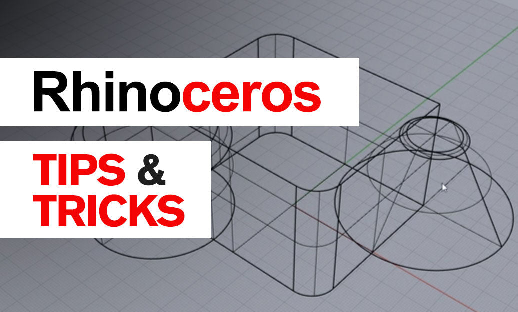

Trimming surfaces with curves is one of Rhino’s most useful NURBS-editing workflows. The Trim command removes selected portions of a surface without changing the underlying surface geometry, making it ideal for creating openings, boundaries, and complex product-form details quickly.
In Rhino, a trimmed surface still contains its original untrimmed rectangular parameter space. The visible edge may look complex, but it is defined by trimming curves placed on the underlying surface. Understanding this distinction helps prevent common modeling and export problems.
Basic trimming workflow
- Create or identify the surface to edit.
- Create a cutting curve that lies on, crosses, or can be projected onto that surface.
- Run
Trim. - Select the cutting curve, edge, surface, or polysurface as the cutting object.
- Press Enter, then click the region of the surface you want to remove.
Rhino accepts several cutter types, including curves, surface edges, other surfaces, polysurfaces, and extrusion edges. When the cutter does not already lie on the target surface, Rhino may use the active view direction to determine the trim projection. For predictable results, work in a view perpendicular to the intended cutting direction whenever possible.
Use the right curve placement method
-
Project: Use
Projectwhen a planar curve must be projected in a specific construction-plane or viewport direction onto a curved surface. -
Pull: Use
Pullwhen you need the curve to follow the closest-point relationship across the target surface. -
Intersect: Use
Intersectto generate precise cutting curves where two surfaces physically meet. -
DupEdge: Use
DupEdgeto reuse an existing surface or polysurface edge as a matching cutter.
A reliable practice is to retain the original cutting curves on a separate construction layer. This makes later revisions much easier, particularly when a client changes the size, location, or shape of an opening.
Important trimming best practices
- Ensure curves actually intersect the surface area you intend to trim. A curve that only appears to touch in one viewport may miss the surface in 3D.
- Use
Splitinstead ofTrimwhen you want to preserve every resulting surface region. Split is often safer during exploratory modeling. - Avoid excessively tiny trim segments. Small, fragmented boundaries can complicate fillets, offsets, booleans, meshing, and downstream manufacturing exports.
- Use
ShowEdgesto inspect naked edges after trimming a polysurface or solid. - Run
ShrinkTrimmedSrfwhen a trimmed surface has a much larger underlying surface than its visible area. This can improve file efficiency and reduce later editing confusion.
If Trim fails, first check the cutter and target with What or Check. Then confirm that object snaps have not introduced a small gap, that the model tolerance is appropriate, and that the cutting curve has enough overlap with the target. Extending the cutter beyond the surface boundary is often a simple and effective fix.
After trimming, inspect the result in shaded mode and use ShowEdges before continuing with operations such as Join, OffsetSrf, or Boolean commands. Clean trimming is a foundation for dependable Rhino models, whether the final output is a render, drawing, CNC file, or 3D print.
For Rhino software, training, and workflow resources, visit NOVEDGE’s Rhino collection and explore additional professional design tools at NOVEDGE.
You can find all the Rhino products on the NOVEDGE web site at this page.
Also in Design News