Your Cart is Empty
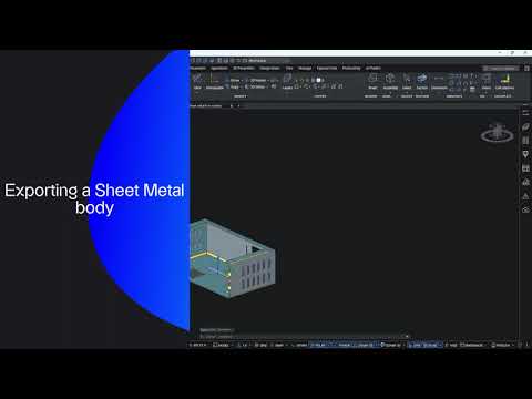
Rhino 3D Tip: Preparing Rhino Models for CNC Fabrication

When preparing a Rhino model for CNC, the goal is not just to make geometry that looks correct on screen, but geometry that machines cleanly, safely, and predictably. A well-prepared file reduces setup time, prevents toolpath errors, and helps avoid costly fabrication mistakes.
Here are a few practical habits that can improve your Rhino CNC workflow.
-
Model with manufacturing in mind from the start.
Avoid building forms that ignore cutter access, stock thickness, tool diameter, or machine limits. Sharp internal corners, for example, may look perfect in Rhino, but a round end mill cannot produce them without relief details.
-
Keep geometry clean and simplified.
Before exporting, remove duplicates, stray curves, tiny fragments, and unused construction geometry. Use commands like SelDup, SelBadObjects, Check, and ShowEdges to identify issues early. Clean input geometry leads to more reliable CAM results.
-
Use layers to separate fabrication intent.
Organize cut geometry by operation:- Profiles
- Pockets
- Drill locations
- Engraving curves
- Reference geometry
-
Confirm that curves are truly machinable.
CNC workflows often depend on high-quality 2D or 2.5D curves. Make sure profiles are closed where needed, linework is planar, and overlapping segments are removed. Commands such as Join, ClosedCrv, PlanarSrf, and ProjectToCPlane can help prepare accurate boundaries.
-
Check tolerances and units before export.
A mismatch in units or loose tolerances can create real manufacturing problems. Verify whether your job is in millimeters or inches and make sure your Rhino file matches the CAM environment. Consistency here is essential for part accuracy, fit, and repeatability.
-
Design for tool diameter, not just shape.
One of the most common CNC preparation mistakes is forgetting the physical cutter. Consider:- Minimum inside radius
- Narrow slots smaller than the tool
- Deep pockets with difficult chip evacuation
- Tall walls prone to vibration
-
Use Rhino analysis tools as a quality checkpoint.
Measure distances, inspect edge continuity, and verify thicknesses where needed. For 3-axis work, it is also useful to confirm what is vertical, horizontal, or draft-sensitive before creating toolpaths.
-
Prepare solids and surfaces intentionally.
For some CAM workflows, closed solids are ideal. For others, well-structured surfaces or clear drive curves are better. The important thing is to know what your downstream software expects and export accordingly, whether that means STEP, IGES, DXF, or another format.
A strong Rhino-to-CNC workflow is built on clarity, organization, and manufacturable geometry. The more fabrication logic you embed into the model, the fewer surprises you will face in machining.
For Rhino software, training, and workflow tools, explore Rhino at NOVEDGE. If you are building a professional digital fabrication pipeline, NOVEDGE is also a great resource for design software and production solutions.
You can find all the Rhino products on the NOVEDGE web site at this page.
Also in Design News