Your Cart is Empty
Parametric Product Families in Alibre: Master Variable Schemas, Guardrails, Skeleton Sketches, and Equation-Driven Configurations
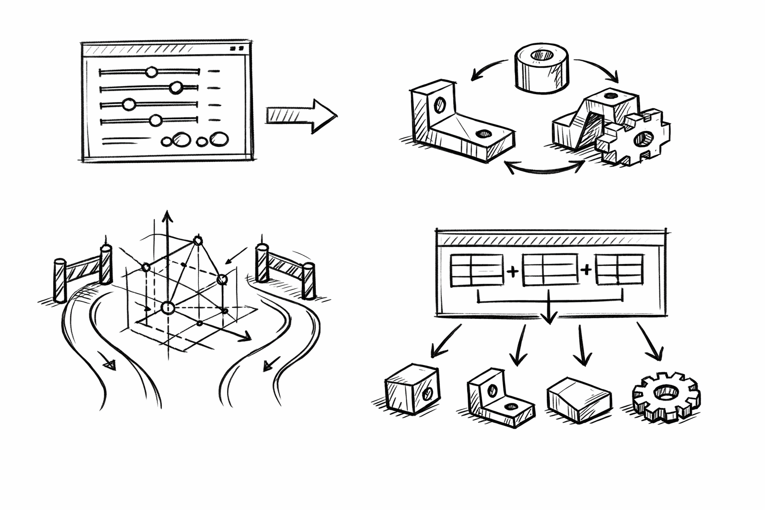


Parametric product families in an Alibre context are parts (or assemblies) that share the same underlying geometric logic—sketch intent, feature order, and constraints—while producing multiple size and feature variants from a single model. Done well, this approach uses Variables and Equations to reduce the number of separate files you maintain, minimize rebuild failures during edits, and accelerate configuration changes when requirements shift.
The focus here is not generic “use parameters” guidance. The goal is five advanced, repeatable techniques you can apply to make Alibre models behave like scalable product platforms: a master schema for variables, explicit guardrails, equation-driven suppression for true variants, skeleton-driven layout geometry, and a configuration workflow that scales without becoming brittle.
Build a “Master Variable Schema” that scales across an entire family
A robust family starts with a variable system that reads like a spec sheet and behaves like an API. If the schema is inconsistent, every equation becomes harder to trust, every downstream reference becomes harder to interpret, and configurations become difficult to extend without breaking something.
Establish a naming system that reads like a spec sheet
Use short names that correspond to what users, manufacturing, and documentation already recognize. Resist the temptation to encode feature history (“Extrude1Depth”) and instead encode intent (“Len”). Common examples that scale well across many mechanical families include:
-
Size and envelope:
OD,ID,Wall,Len,OverallWidth,OverallHeight -
Fasteners and mounting:
BoltCircle,MountPattern,HoleDia,FastenerDia,Clearance -
Manufacturing limits:
MinWall,ToolRadius,MinFillet,MinDraft -
Threading and repetition:
Pitch,HoleCount,EndMargin
When variables are named by intent, the same equations can be reused across multiple families, and a collaborator can infer design logic without opening every feature dialog.
Create variable types by intent (and keep them separated)
Most variable sprawl happens when “inputs,” “computed outputs,” and “constraints” are mixed together. Separate them by role so you can scale the family while keeping edits safe.
-
Primary drivers: customer-facing catalog sizes such as
OD,Len,FastenerDia,HoleCount. These are the only values that should typically vary per SKU. -
Derived dimensions: computed values that define internal geometry and offsets, such as
ID,HoleOffset,RibThk. These should rarely be directly edited and should primarily exist to make logic readable and stable. -
Process/manufacturing constraints: safety rails like
MinWall,MinFillet,ToolRadius,MinDraft. These should not be overwritten by configuration rows unless you intentionally support different manufacturing processes.
In practice, many teams keep a consistent prefix convention (for example, U_ for user inputs, D_ for derived, M_ for manufacturing). Even without prefixes, keeping a dedicated “inputs only” block at the top of the variable list makes audits and table mapping significantly easier.
Implement “canonical” equation blocks
Standard equation patterns—reused across parts—are where a family becomes more than resized copies. A few canonical blocks cover most product family logic:
Thickness and clearance relationships keep internal features consistent as envelope sizes change:
ID = OD - 2*WallHoleDia = FastenerDia + Clearance-
CounterboreDia = HeadDia + Clearance(when applicable)
Feature placement logic drives patterns and evenly distributed geometry without manual re-dimensioning:
UsableLen = Len - 2*EndMarginHoleOffset = UsableLen / (HoleCount - 1)
Even if Alibre’s expression syntax differs from other CAD tools you’ve used, the underlying strategy is the same: treat equations as reusable “behavior blocks” that you can copy into new families with minimal edits.
Prevent variable sprawl and broken references
As families grow, the risk shifts from “not enough parameters” to “too many loosely-consistent parameters.” A few governance habits prevent most long-term failures:
-
Avoid duplicate meanings: one variable per concept. If you have both
WallandThkthat sometimes mean the same thing, you will eventually create conflicting equations. - Be explicit about units expectations: decide whether your schema assumes mm or inches, and keep angles consistently in degrees. “Unit ambiguity” is a frequent cause of silent wrong geometry, not just hard rebuild errors.
- Audit periodically: remove unused variables, rename ambiguous ones, and resolve conflicts before they propagate into drawings, BOM properties, and exported files.
In Alibre, broken references often show up not when you add equations, but when you later suppress features or insert new ones that shift face/edge identity. A clean schema reduces the number of “mystery dimensions” that accidentally bind to unstable geometry.
Encode design rules with constraints and guardrails (min/max logic, clamping, sanity checks)
If a family can be configured into invalid geometry, it will be—whether by a design table edit, a rushed change, or a misinterpreted requirement. Guardrails are not “nice to have”; they are how you convert a parametric model into a controlled product platform.
Use equation-driven hard limits to prevent invalid geometry
When an input is risky, clamp it. The classic example is wall thickness. Even if you allow a user-facing wall request, you still need a manufacturing-safe minimum.
Typical patterns look like:
Wall = max(UserWall, MinWall)Fillet = min(UserFillet, 0.45*Wall)
If your Alibre expression set does not support a direct min()/max(), the same behavior can be constructed with conditional expressions (or by defining alternate derived variables and selecting between them). The key concept is that user-facing variables should feed into the model through a safety layer, not directly into fragile features.
Create build-safe thresholds for patterns and thin features
Patterns, shell-like regions, and thin extrusions are common rebuild failure triggers—especially when a family spans a wide size range. Build-safe thresholds reduce these failures by ensuring inputs cannot force negative lengths, zero-thickness edges, or impossible offsets.
Examples of enforceable relationships include:
-
Minimum edge margin: keep fasteners away from ends and edges by ensuring
EndMarginis never too small relative to structure, such asEndMargin = max(UserEndMargin, 2*Wall). -
Avoid negative results: ensure computations cannot cross zero, such as forcing
IDto remain positive through a consistent relationship betweenOD,Wall, and minimums. -
Tool-driven logic: prevent slots or pockets from collapsing below machinable limits, such as
SlotWidth >= 2*ToolRadiusby clampingSlotWidthto a safe minimum.
These relationships also improve performance: when sketches do not self-intersect and features do not “flip” due to changing sign, Alibre rebuilds tend to be faster and more predictable across configuration rows.
Drive error visibility via diagnostic variables
Guardrails should also be visible. Diagnostic variables provide a lightweight way to surface rule breaks without manually scanning the model. The idea is to compute “flags” that become obvious in the Variables list or in a design table review.
Common patterns are 0/1 flags:
-
IsTooThin: set to 1 whenWallhits the minimum (or whenUserWallis belowMinWall). -
IsHoleTooClose: set to 1 when a computed edge distance falls below a threshold. -
IsInvalidSpacing: set to 1 whenHoleCountandLenproduce spacing below a minimum drill-to-drill distance.
Even if these variables do not stop a rebuild, they convert “silent risk” into something you can filter and correct before release. In families with dozens or hundreds of configurations, that visibility is often the difference between a scalable library and a fragile one.
Define family boundaries explicitly
A family is not “infinite.” It has a valid envelope where geometry, manufacturing, and performance assumptions hold. Those boundaries should be explicit and discoverable.
Document valid ranges alongside variables (in notes, property text, or a shared specification that mirrors the variable schema). For example:
-
OD: 20–120 -
Len: 30–300 -
HoleCount: 2–10
Also separate engineering-safe limits (what can be modeled and manufactured reliably) from catalog limits (what you intend to sell). Catalog limits change more often than engineering limits, and confusing the two leads to unnecessary model edits and accidental “specials” that weren’t designed to be supported.
Use equation-controlled feature suppression to create true family variants (not just resized copies)
Scaling a family is not only about sizes. Real product lines introduce feature variants: ribs appear on larger sizes, mounting schemes change across diameter bands, venting patterns exist only for certain environments, and so on. Equation-controlled suppression lets one model behave like multiple variants while staying stable.
Identify which features should be conditional across the family
Focus on features that represent meaningful functional branching, not cosmetic micro-edits. Common conditional candidates include:
- Optional ribs, gussets, and stiffeners
- Vents or weight reduction pockets
- Keyways or anti-rotation flats
- Mounting patterns (2-hole vs 4-hole, slotted vs round)
- Counterbores/countersinks when fastener choices change
- Seal grooves when environmental variants exist
Every conditional feature should map to an intentional business or engineering variant, not just “something that looked good in one size.” Otherwise, suppression logic turns into an unmaintainable maze.
Drive suppression with discrete state variables (“mode switches”)
Use discrete variables to represent variant states. Treat these as part of the visible configuration interface, similar to selecting options on a configurator.
-
HasRibs= 0/1 -
SealGroove= 0/1 -
MountType= 1..N
Then tie feature suppression to these variables. The model becomes easier to reason about because “why did that rib disappear?” is answered by a single variable rather than by tracing five dependent dimensions.
Link suppression logic to size thresholds (automatic variant selection)
To reduce manual configuration work, compute mode switches from primary drivers when possible. For example, ribs might only be necessary above a span length:
HasRibs = (Len > 150)
Mounting might change above a diameter where bolt circle constraints force a different pattern:
MountType = (OD < 60) ? 1 : 2
Use the conditional pattern that Alibre supports in its equation system. The critical behavior is deterministic selection: the same input always yields the same variant state, which keeps drawings, BOM properties, and exports consistent.
Keep rebuild stability when toggling features
Suppression is notorious for destabilizing rebuilds because downstream features may reference faces or edges that disappear. To keep the family robust:
- Build references that survive suppression: rely on reference planes, axes, and persistent sketches as anchors.
- Avoid downstream dependencies on volatile faces: do not dimension critical sketches to fillet edges or to faces created only when a feature is present.
- Prefer “skeleton” geometry that always exists (even if the final feature is suppressed) so references remain valid across all states.
A good test is to flip each mode switch back and forth while watching which dimensions and constraints remain stable. If a suppression toggle changes sketch references, expect table-driven configurations to eventually fail in batch rebuilds.
Standardize variant outcomes for downstream usage
Variants are only useful if downstream outputs react predictably. Ensure drawings and properties are tied to stable variables rather than feature presence. For example:
- Use a variable-driven note for mounting type rather than relying on a user remembering which pattern is active.
- Make part naming conventions depend on the state variables (
MountType,SealGroove) so exported files match the geometry unambiguously.
This is where equation-controlled feature suppression becomes a product-line mechanism, not just a modeling trick.
Centralize calculations with “skeleton sketches” and equation-driven layout geometry
Most parametric instability comes from features referencing each other’s faces in a long chain. Skeleton-driven modeling reduces that coupling by making one or more master sketches define the critical layout: axes, envelopes, interfaces, and keep-out zones.
Create a layout-first architecture
Start with a master sketch (or a small set of sketches) that defines:
- Primary axes and datum centerlines
- Overall envelope geometry (outer bounds and major thickness regions)
- Interface geometry (hole center locations, mounting planes, sealing land boundaries)
- Keep-out zones that represent clearance requirements
Downstream features should reference this skeleton geometry rather than referencing faces created by previous features. The result is fewer circular dependencies and fewer “face ID” problems when the model changes across variants.
Drive sketch dimensions by variables and derived equations
Skeleton sketches become powerful when every important dimension is variable-driven. This is where “derived dimensions” earn their keep: they make the skeleton readable, maintainable, and consistent across configurations.
Examples:
-
Envelopes:
OverallWidth,OverallHeight,KeepOutZonederived fromOD,Len, and clearance rules. -
Interface points: hole centers and slot endpoints computed from
BoltCircle,HoleCount,EndMargin, and symmetry constraints. -
Mounting datum shifts: offsets that change with
MountTypebut remain anchored to the same datums.
When the skeleton is correct, the rest of the model is largely an execution of that intent: extrudes, revolves, patterns, and cuts that read from a stable blueprint.
Use equation patterns to prevent parametric drift
Parametric drift happens when multiple dimensions “stack” off each other over time, causing cumulative misalignment as configurations change. Two strategies reduce this dramatically:
- Symmetry anchoring: dimension critical geometry from centerlines and midplanes. For example, place hole patterns with a center datum and distribute in both directions rather than “from one end.”
-
Even spacing logic: define spacing as a derived quantity from usable length, such as
Spacing = UsableLen/(N-1), and drive sketch pattern points from that spacing. This keeps endpoints stable and avoids rounding drift across variants.
In many families, simply switching from edge-based dimensions to centerline-based dimensions eliminates the majority of rebuild anomalies when sizes cross thresholds.
Make design intent readable for collaborators
Skeleton sketches can become messy if treated as “just a sketch.” To keep them readable:
- Group dimensions conceptually: interfaces together, structure together, manufacturing constraints together.
- Mirror the variable schema in the sketch: if the schema has “mounting,” “envelope,” and “process,” the sketch should reflect those clusters.
- Use annotations to document why relationships exist (clearance standard, strength requirement, tool limit). The goal is to preserve intent, not just geometry.
The benefit is not only collaboration. Readable intent makes future refactors safer when a product line evolves (new mounting style, different fastener standard, new minimum wall requirements).
Improve configurability for visualization and product-line consistency
Silhouette-controlling dimensions should come from the same variables used in marketing renders, catalogs, and product documentation. When OD and Len drive both geometry and properties, you avoid the mismatch where a model “looks like” one size but gets exported or labeled as another.
This is a subtle but critical outcome of skeleton-driven design: it aligns CAD behavior with how the product line is described externally. That alignment pays off when you automate exports, generate configuration-based renders, or publish dimensional tables.
Implement a scalable “Family Configuration Workflow” using Design Tables + equation sets
Once the model logic is stable, scalability depends on how you create and verify configurations. The workflow should let you add SKUs confidently without turning configuration management into manual bookkeeping.
Structure variables so they map cleanly into configurations
The most scalable configuration strategy is to expose a minimal set of inputs per SKU and derive everything else. The design table should primarily contain:
-
Primary drivers (customer-facing):
OD,Len,FastenerDia,HoleCount -
Mode switches:
HasRibs,MountType,SealGroove
Avoid placing derived values in the table unless you need them for audit, QA, or reporting. If a derived value is in the table, someone will eventually edit it and break the design rule that should have computed it.
Build a design table strategy for small-to-large families
Two complementary approaches cover most families:
Catalog row approach: each row corresponds to a sellable variant, and columns represent the primary drivers plus mode switches. This is best for discrete product lines where each SKU is intentional, documented, and maintained long-term.
Programmatic row approach: variants are generated systematically (diameter increments, length series, standard hole counts). This is best when you want a regular size series and you can encode the “series logic” into equations and a predictable table structure.
In both cases, the table should feel like a product definition, not like a list of feature edits. If adding a variant requires touching ten columns, it is usually a sign that too many values are not derived.
Create reusable equation presets for different product lines
One of the most powerful strategies is using “factor variables” to derive different strength or manufacturing behaviors from the same base geometry. Instead of duplicating models for light-duty and heavy-duty versions, define equation presets by adjusting a small set of factors:
-
WallFactor: multiplies baseline wall thickness logic -
RibFactor: scales rib thickness/height rules -
SafetyFactor: influences minimum edge distances, minimum fillets, or other conservative constraints
For example, you might define Wall = max(UserWall, MinWall)*WallFactor and then set WallFactor to 1.0 for standard and 1.2 for heavy-duty. This turns the family into a platform where “product line” becomes a controlled configuration choice, not a separate file.
Validate variants efficiently
Scalable families require batch validation habits. At minimum:
- Run quick rebuild checks across all design table rows after any change to skeleton geometry, suppression logic, or manufacturing constraints.
- Review diagnostic variables (
IsTooThin,IsHoleTooClose, spacing flags) to detect configurations that technically rebuild but violate rules. - Create lightweight QA metrics from variables, such as target mass bands, minimum wall compliance indicators, or hole count logic validations.
This is where earlier investments pay off. If guardrails and flags exist, validation becomes table review and targeted fixes, not trial-and-error modeling.
Ensure downstream deliverables scale with the family
Families fail operationally when geometry is configurable but documentation and exports are not. Tie downstream deliverables to variables so that naming, properties, and exports can be automated and remain consistent.
Common patterns include variable-driven part numbers and descriptions:
PartNumber = "XX-" + OD + "-" + Len-
DescriptionreferencesMountTypeandSealGroovestate variables
Likewise, establish rendering/export standards (STEP/STL) that are keyed to configuration state so that the files coming out of Alibre match the catalog definition. When you later expand the family, the pipeline does not change—only the configuration rows do.
Conclusion
The five techniques form a practical progression: start with a scalable schema, add guardrails, introduce variant logic through suppression, stabilize the model with skeleton-driven layout geometry, and then scale configurations through design tables and reusable equation sets. The overall payoff is straightforward: fewer models to maintain, fewer rebuild failures when sizes change, and significantly faster expansion of a consistent product line.
A strong next exercise is to refactor one existing part into a family using only 3–5 primary drivers, then expand iteratively. If you can add ten new configurations by editing a table (instead of copying files), while rebuilds remain stable across suppression states, you have converted a single model into a reusable product platform.
Also in Design News


