Your Cart is Empty




Open Standards as Pipeline Infrastructure
Why interoperability has become a strategic concern
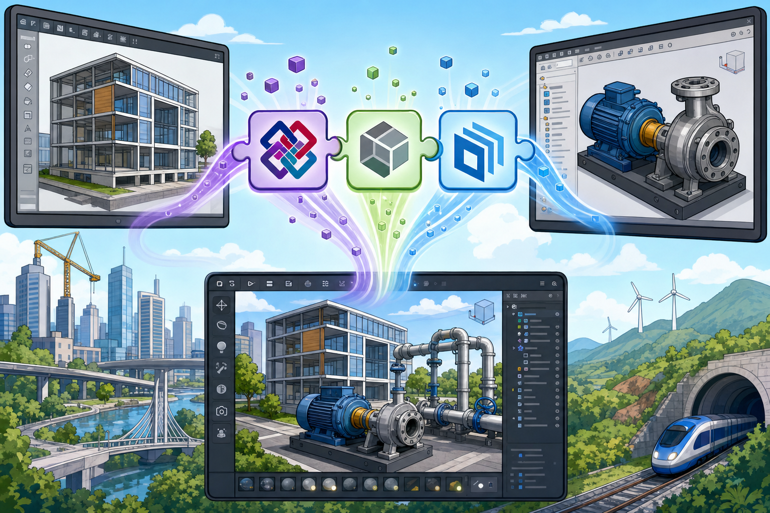
Modern design work no longer lives inside a single application, a single department, or even a single discipline. A building project may begin with conceptual massing, move through BIM authoring, structural analysis, energy simulation, fabrication detailing, construction coordination, asset management, and eventually into a digital twin used for operations. A manufactured product may move from industrial design to parametric CAD, simulation, topology optimization, CAM, additive manufacturing preparation, product lifecycle management, configurator visualization, and augmented reality service documentation. Each stage introduces specialized tools that are extremely capable in their own domain but rarely speak the same native data language. This is why open standards are becoming essential infrastructure rather than optional export conveniences. They provide a neutral foundation for moving geometry, metadata, relationships, and context between applications that were never designed to be part of one monolithic software environment.
The expanding design ecosystem
The complexity is amplified by the way teams now collaborate. Mechanical engineers may use one CAD platform while manufacturing partners use another. Architects may develop models in one BIM authoring tool while contractors coordinate construction sequencing in different platforms. Visualization teams often need assets from CAD, BIM, scan data, simulation environments, material libraries, and animation tools. Product teams build digital twins by combining sensor streams, assembly structures, maintenance records, and high-fidelity geometry. In this environment, closed files become bottlenecks because every conversion can remove a layer of meaning. Open standards address this by creating shared exchange languages for multi-tool workflows. They make it possible to reduce vendor lock-in, preserve design data across software boundaries, and maintain useful information long after a specific application version has disappeared from production use.
- CAD systems define precise product geometry and assemblies.
- BIM systems organize spaces, systems, classifications, and construction data.
- CAE platforms require analysis-ready geometry, materials, loads, and constraints.
- CAM platforms need manufacturable features, tolerances, setups, and toolpath context.
- Visualization and digital twin environments require lightweight, layered, and interactive scene data.
The Core Problem Open Standards Address
Moving more than shapes between tools
At first glance, interoperability may appear to be a file conversion problem: export a model from one system, import it into another, and continue working. In practice, the challenge is much deeper. A model is not merely a collection of surfaces, solids, meshes, and dimensions. It also contains intent: how components relate, what materials they use, which spaces they belong to, how they should be manufactured, what regulatory definitions they satisfy, and which downstream tasks depend on them. A wall in a BIM model is not simply a rectangular solid; it may define fire rating, acoustic performance, material layers, room boundaries, structural behavior, and maintenance responsibilities. A mechanical assembly is not simply a group of solids; it may define constraints, product structure, tolerances, materials, finishes, and manufacturing dependencies. Preserving design intent is the real interoperability challenge.
Long-term accessibility and cross-discipline collaboration
Open standards help teams protect design information from being trapped in proprietary formats whose compatibility may change over time. Long-term data accessibility is especially important for infrastructure, aerospace, industrial equipment, public works, medical devices, and facilities that may remain in service for decades. A bridge, hospital, aircraft component, or industrial plant cannot depend entirely on the commercial roadmap of one software vendor for data continuity. Open standards also support collaboration between disciplines that organize information differently. Architects describe spaces and systems; mechanical engineers describe functional assemblies; fabricators describe manufacturable parts; visualization specialists describe materials, lighting, cameras, and scene variants. No single open standard solves all of these needs equally, which is why three standards have become especially important in contemporary design software pipelines: IFC, STEP, and USD.
- IFC focuses on building and infrastructure information exchange.
- STEP focuses on mechanical CAD and product data interoperability.
- USD focuses on scene description, composition, visualization, and real-time 3D collaboration.
IFC as the Backbone of Open BIM
Buildings as semantic information systems
Industry Foundation Classes, commonly known as IFC, is the dominant open standard for BIM data exchange across architecture, engineering, construction, and facility management workflows. Its primary value is not that it can transfer geometry, although it can. Its deeper value is that it can describe buildings as structured information systems. IFC can represent walls, slabs, doors, windows, beams, columns, ducts, pipes, spaces, zones, systems, materials, classifications, and property sets. It can preserve spatial relationships such as which room a door belongs to, which level a component is placed on, and how systems are organized through a facility. This makes IFC much more than a neutral 3D model format. It is a semantic framework for exchanging building information across software boundaries while retaining a meaningful connection to design, construction, and operations processes.
Regulatory, operational, and lifecycle value
IFC becomes particularly valuable when the model must support tasks beyond design authoring. Regulatory checking, quantity takeoff, energy modeling, fire safety review, accessibility verification, facility management, and digital twin operations all depend on structured data rather than visual geometry alone. For example, a facility management platform may not need every modeling feature that created a wall, but it does need to know that the object is a wall, what it is made of, what space it bounds, what fire rating it has, and which maintenance policies apply. Infrastructure and public-sector workflows increasingly rely on open BIM deliverables because they provide a transparent and auditable way to exchange building data. The practical lesson is that IFC should be treated as a data-rich BIM exchange layer, not as a simple model export button used only at project handover.
- Architectural coordination benefits from spaces, levels, zones, and object classifications.
- Structural coordination benefits from beams, columns, slabs, materials, and analytical relationships.
- MEP coordination benefits from systems, equipment, ducts, pipes, fittings, and connectors.
- Operations teams benefit from asset data, maintenance properties, and spatial indexing.
STEP as the Workhorse of Mechanical Product Exchange
Precise product geometry across CAD systems
The Standard for the Exchange of Product Model Data, better known as STEP, is one of the most important standards in mechanical design and manufacturing. It is widely used in aerospace, automotive, industrial equipment, consumer products, tooling, medical devices, and supplier collaboration. Its most visible strength is the reliable transfer of precise boundary representation geometry between CAD systems. When a manufacturer needs to send a housing, bracket, turbine component, mold insert, or complex assembly to a partner using a different CAD system, STEP is often the most practical neutral format. Compared with many direct native-file conversions, STEP can be more predictable because it is designed specifically for product model exchange. It is especially valuable when the downstream user needs accurate solids and surfaces for measurement, machining preparation, packaging design, interference analysis, or inspection planning.
Beyond simple solids
STEP is often described as a geometry exchange format, but that description undersells its broader role. Depending on the application protocol and the quality of implementation, STEP can carry product structure, assemblies, colors, layers, materials, validation properties, geometric dimensioning and tolerancing information, manufacturing data, and configuration-related context. This broader capability is important because mechanical product development depends on more than shape. A precise machined component may require tolerances, surface finish requirements, material identity, and assembly relationships to remain useful beyond visual reference. In advanced manufacturing workflows, preserving this product information reduces interpretation errors and supports automation. Still, teams should understand what their specific tools actually export and import. A STEP file produced by one system may contain rich product manufacturing information, while another may contain only clean solids with basic assembly hierarchy. Implementation quality matters as much as the standard itself.
- STEP is usually appropriate for exchanging accurate CAD solids and assemblies.
- It is widely accepted across manufacturing supply chains.
- It can support richer product data when the selected implementation and application protocol allow it.
- It is not a guaranteed carrier of parametric feature history or native CAD design logic.
USD as the Emerging Standard for Complex Scenes
From visual effects to industrial visualization
Universal Scene Description, or USD, originated in high-end film and visual effects pipelines, where teams needed to manage enormous animated scenes with many contributors working in parallel. That heritage is important because USD was designed for composition, layering, referencing, variants, animation, materials, lighting, cameras, and scalable scene assembly. These capabilities are now highly relevant to design software because product visualization, robotics simulation, virtual production, architectural experience design, digital twins, and real-time engineering review increasingly require environments larger and richer than a single CAD file. A car configurator, factory simulation, urban digital twin, or immersive architectural review may contain many assets from many sources, each authored by different teams and updated at different rates. USD provides a powerful way to compose those assets without collapsing everything into one static file.
Layers, variants, and interactive collaboration
USD differs from IFC and STEP because it is less focused on engineering-authoring semantics and more focused on scene composition. Its strength is the ability to reference assets, override properties in layers, switch variants, manage materials, and stream complex scenes into visualization and simulation environments. A product team can represent multiple colorways, trim levels, accessory configurations, and lighting setups without duplicating the entire data set. A robotics team can assemble a simulated warehouse from reusable assets and update individual components while maintaining the larger scene. A visualization team can receive CAD-derived geometry, assign physically based materials, add cameras, create animations, and publish the scene for real-time review. USD is therefore becoming attractive wherever design data must be transformed into interactive, high-fidelity environments that support collaboration, simulation, and decision-making rather than only engineering documentation.
- USD handles large scenes through references, payloads, and composition arcs.
- It supports material workflows commonly used in visualization and real-time rendering.
- It enables variants for configurations, options, levels of detail, and presentation states.
- It is increasingly relevant to digital twins, robotics, simulation, and immersive design review.
Comparing the Strengths of IFC, STEP, and USD
Different standards for different kinds of meaning
The most productive way to understand IFC, STEP, and USD is not to ask which one is best, but to ask which kind of meaning each standard is optimized to preserve. IFC is semantically rich for buildings. It understands the idea of spaces, elements, systems, levels, classifications, and property sets that are essential to construction and operations. STEP is precise for engineered products. It is strong where manufactured parts, assemblies, surfaces, solids, tolerances, and product structure need to survive movement between CAD systems. USD is powerful for composition and visualization. It excels when large scenes must be assembled from many sources, layered non-destructively, rendered interactively, and modified collaboratively. Treating them as interchangeable formats leads to confusion because they solve different interoperability problems and reflect different assumptions about what design data should become downstream.
Choosing based on downstream intent
A practical decision framework begins with the downstream task. If the receiving workflow needs BIM classifications, spatial containment, building systems, room data, and lifecycle asset attributes, IFC is usually the appropriate pathway. If the downstream task requires accurate machined geometry, solid modeling interoperability, assembly transfer, or manufacturing preparation, STEP is often the better choice. If the target environment is real-time visualization, simulation, configurator development, virtual production, or large-scene digital twin presentation, USD is increasingly compelling. Many advanced pipelines use more than one of these standards. A campus digital twin might use IFC to preserve building semantics, STEP for equipment geometry provided by manufacturers, and USD to compose the final interactive environment. The key is to design the pipeline around what must remain editable, computable, or inspectable after exchange rather than around what is easiest to export today.
- Use IFC when building intelligence and lifecycle data are primary.
- Use STEP when mechanical precision and product geometry are primary.
- Use USD when scalable scene composition and interactive visualization are primary.
- Use combined pipelines when geometry, semantics, and visualization must coexist.
Open Standards Do Not Guarantee Perfect Interoperability
The gap between specification and production reality
One of the most common misconceptions in design technology is that an open standard automatically guarantees clean interoperability. In reality, a standard defines a shared language, but each software vendor implements that language through its own exporter, importer, data model, and user interface assumptions. Translation failures can still occur. Parameters may be lost, feature history may disappear, units may be interpreted incorrectly, coordinate systems may shift, metadata may be omitted, and assemblies may arrive with broken relationships. Geometry may be simplified to make downstream processing easier, but the simplification may remove edges, faces, or analytic definitions that another workflow needs. A BIM object may arrive as a generic proxy instead of a classified wall or duct. A carefully structured CAD assembly may flatten into disconnected solids. A visualization scene may receive geometry but lose material assignments, hierarchy, or variants.
Why export settings are part of the design pipeline
Export settings are often treated as administrative details, but they can dramatically affect downstream usability. In IFC workflows, the selected schema version, model view definition, property set mapping, classification export, space boundary setting, and coordinate strategy can determine whether the file supports coordination, regulatory checking, or facility management. In STEP workflows, choices related to application protocol, assembly structure, colors, validation properties, and product manufacturing information can determine whether the file is useful for inspection, machining, or supplier review. In USD workflows, decisions about references, payloads, material definitions, unit scale, up-axis, variant organization, and asset paths can determine whether the scene performs well in real time. This means that interoperability is a workflow design problem, not simply a software compatibility problem. Teams need repeatable exchange rules, not occasional manual exports guided by memory.
- Lost parameters can reduce automation and reporting value.
- Incorrect units can create expensive scale and manufacturing errors.
- Coordinate problems can disrupt BIM coordination and digital twin alignment.
- Missing metadata can make models useless for lifecycle or compliance workflows.
- Broken hierarchies can compromise assemblies, scenes, and asset management.
Geometry, Semantics, Intent, and Workflow Interoperability
Four levels of exchange maturity
To manage open standards effectively, teams should distinguish between four levels of exchange maturity: geometry exchange, semantic data exchange, design intent preservation, and workflow-level interoperability. Geometry exchange is the most basic level. It answers the question: did the shape arrive correctly? This is critical for machining, clash detection, visualization, and spatial coordination, but it is not enough for advanced design automation. Semantic data exchange goes further by asking whether the receiving application understands what the objects are. In BIM, this means recognizing a component as a door, air terminal, pump, beam, or space rather than an anonymous solid. In product design, it may mean preserving assemblies, part identities, material names, and product structure. Semantics are what allow software to compute meaning rather than merely display objects.
Intent and process continuity
Design intent preservation is harder because it asks whether the logic behind the model survives translation. A native CAD model may contain parametric sketches, constraints, features, equations, pattern definitions, and design tables. A BIM model may contain hosted relationships, system connectivity, parametric families, and rule-based object behavior. Most neutral exchanges do not preserve all of this authoring intelligence. They preserve selected outcomes rather than the procedural recipe that created them. Finally, workflow-level interoperability asks whether the exchanged data supports the actual downstream task without excessive rework. A file can be geometrically correct and semantically rich yet still fail if it lacks the attributes needed for procurement, simulation, energy analysis, robotic manipulation, or field installation. Mature teams judge interoperability by operational usefulness, not by whether a file merely opens without errors.
- Geometry exchange asks whether the shape is correct.
- Semantic exchange asks whether objects retain meaning.
- Intent preservation asks whether authoring logic survives.
- Workflow interoperability asks whether the next task can proceed efficiently.
Implementation Inconsistencies Across Software Vendors
Same standard, different practical behavior
Even when teams agree to use IFC, STEP, or USD, outcomes can vary because software platforms implement standards differently. Some vendors prioritize export fidelity for geometry, while others prioritize property data, hierarchy, performance, or compatibility with specific downstream applications. A tool may support an older schema version but not newer capabilities required by a project. Another may import a standard file but map objects into generic internal categories that lose useful semantics. A STEP importer may heal surfaces aggressively, which helps create watertight solids but may alter analytic precision. A USD pipeline may support basic meshes and materials but not the full range of composition features, variants, or layer behaviors expected by a visualization team. These differences are not always visible in marketing documentation, so technical validation matters more than checkbox-level format support.
Enterprise adoption and version lag
Standards also evolve faster than many enterprise pipelines can adapt. Large organizations often maintain validated software environments for years because updates affect training, automation scripts, regulatory compliance, supplier requirements, and production stability. As a result, a team may want to use a newer schema or richer data exchange capability, while a partner or internal department can only consume an older subset. This creates a practical interoperability negotiation. The solution is not simply to demand the newest format, but to define exchange requirements that are testable. Teams should document which schema versions are acceptable, which properties are mandatory, which coordinate reference systems must be used, which units are allowed, how assemblies should be structured, and how materials should be named. In mature pipelines, standards governance becomes part of digital engineering practice, much like naming conventions, model checking rules, and release management.
- Confirm which schema versions are supported by each tool.
- Test importer behavior, not only exporter capability.
- Define required metadata before project exchange begins.
- Maintain controlled templates for repeatable exports.
Validation as a Required Layer of the Pipeline
Trust but verify every exchange
Because open standards reduce but do not eliminate translation risk, validation must become a formal part of the design pipeline. Automated model checking can detect missing classifications, invalid object types, impossible dimensions, duplicate identifiers, unassigned materials, incorrect coordinates, and incomplete property sets. Metadata audits can confirm that required attributes have survived export and import. Translation quality assurance can compare source and destination models for geometry deviation, assembly count, object naming, hierarchy, material mapping, and property completeness. Round-trip testing can reveal whether data remains stable when exported, imported, modified, and exported again. This is especially important in workflows where design data becomes contractual, regulatory, manufacturable, or operational. A visually correct model may still be defective if the metadata required for downstream automation has silently disappeared during translation.
Practical validation tactics
Validation should be designed around the intended use of the model. For BIM exchange, quality checks might verify classification codes, space containment, level assignment, system connectivity, property sets, and coordinate reference alignment. For mechanical STEP exchange, checks might verify solid validity, mass properties, bounding boxes, assembly hierarchy, units, material assignment, and critical face integrity. For USD scene exchange, checks might verify asset references, texture paths, variant sets, material bindings, unit scale, up-axis, layer structure, and real-time performance budgets. Advanced teams increasingly automate these checks within continuous integration-style pipelines, especially when large quantities of design assets are published to configurators, simulation environments, or digital twin platforms. The principle is straightforward: the cost of validation is lower than the cost of downstream ambiguity. Open standards provide the exchange language, but validation verifies that the message was actually received correctly.
- Run automated model checks before and after exchange.
- Audit metadata against mandatory project or enterprise requirements.
- Compare geometric deviation when precision matters.
- Test round-trip behavior for workflows that require iterative collaboration.
- Track recurring translation failures and convert them into export rules.
Designing Standards-Based Workflows Strategically
From ad hoc exports to governed exchanges
The most advanced teams do not treat IFC, STEP, and USD as last-minute files produced at the end of a modeling task. They treat them as strategic interfaces between specialized systems. This requires defining internal exchange rules before production work begins. A BIM team may decide which IFC entities and property sets are mandatory for each project phase. A product engineering team may decide which STEP application protocols and validation properties suppliers must use. A visualization group may define USD layering conventions, material naming, unit rules, and variant organization so that assets can flow efficiently into real-time environments. These rules reduce ambiguity and allow automation to scale. Without them, every handoff becomes a negotiation, every import becomes a manual repair exercise, and every downstream team loses confidence in the data.
Metadata deserves the same care as geometry
A strategic standards-based workflow also recognizes that metadata is not secondary. In many modern pipelines, metadata is the difference between a model that can be automated and a model that can only be viewed. Geometry tells software where something is and what shape it has. Metadata tells software what it is, how it behaves, which system it belongs to, what it costs, how it should be maintained, or how it should be manufactured. Losing metadata during exchange can be more damaging than losing small geometric details, especially in digital twin, compliance, asset management, and manufacturing automation workflows. Teams should therefore preserve metadata as carefully as geometry. That means mapping properties deliberately, testing imports regularly, and creating publishing procedures that make information loss visible rather than hidden. Data continuity is now a core design quality, not an administrative afterthought.
- Choose the exchange standard based on the downstream task.
- Define required information before export workflows are built.
- Automate validation wherever repeatability matters.
- Document known limitations and approved workarounds.
- Treat metadata preservation as a production requirement.
Open Standards and the Future of Design Software
Specialized tools connected by shared data layers
The future of design software is unlikely to be defined by one universal file format that makes every tool perfectly interchangeable. Design work is too specialized for that. Architecture, structural engineering, industrial design, mechanical CAD, manufacturing, simulation, visualization, robotics, and operations all require different representations of reality. A simulation solver cares about boundary conditions and mesh quality; a CNC programmer cares about manufacturable faces and setups; a facility manager cares about assets, locations, and maintenance data; a real-time renderer cares about materials, levels of detail, lighting, and performance. The more realistic future is a flexible ecosystem of specialized tools connected by standards-based pipelines that move the right information at the right level of fidelity. IFC, STEP, and USD represent three major pillars of this future because each supports a different mode of design information exchange.
The strategic value of interoperable intent
As digital twins, automated manufacturing, immersive collaboration, AI-assisted design, construction robotics, and simulation-driven development mature, the need for reliable open data exchange will keep increasing. The value of design data will depend not only on how well it was authored, but also on how well it can travel. Teams that understand this will build pipelines where standards are selected deliberately, metadata is governed, validation is automated, and downstream requirements influence upstream modeling decisions. IFC will continue to connect building data across the lifecycle. STEP will continue to enable robust mechanical product exchange across CAD and manufacturing networks. USD will continue to support scalable visualization, simulation, and collaborative scene assembly. The competitive advantage will belong to teams that see standards not as neutral file extensions, but as the connective infrastructure of digital design.
Conclusion: Standards as the Foundation of Resilient Pipelines
Building flexible workflows instead of format dependency
Open standards are becoming essential infrastructure for modern design pipelines because they reduce dependence on isolated software environments and make design information more durable, portable, and useful. IFC, STEP, and USD do not compete as equivalents; they solve different interoperability problems. IFC connects building information across design, construction, regulation, operations, and digital twin workflows. STEP enables robust exchange of mechanical product geometry and related product data across engineering and manufacturing ecosystems. USD supports large-scale scene composition, high-end visualization, simulation, variants, animation, and real-time collaboration. The most capable organizations will choose the right standard for the right workflow, define internal exchange rules, automate validation, and preserve metadata with the same discipline they apply to geometry. The future will depend less on a single perfect format and more on flexible, standards-based pipelines that move geometry, data, and intent across specialized tools without forcing every discipline into the same software model.