Your Cart is Empty
From Parametric Intent to Production: A Traceable Workflow for Simulation, DfAM, and Verification-Grade Visualization
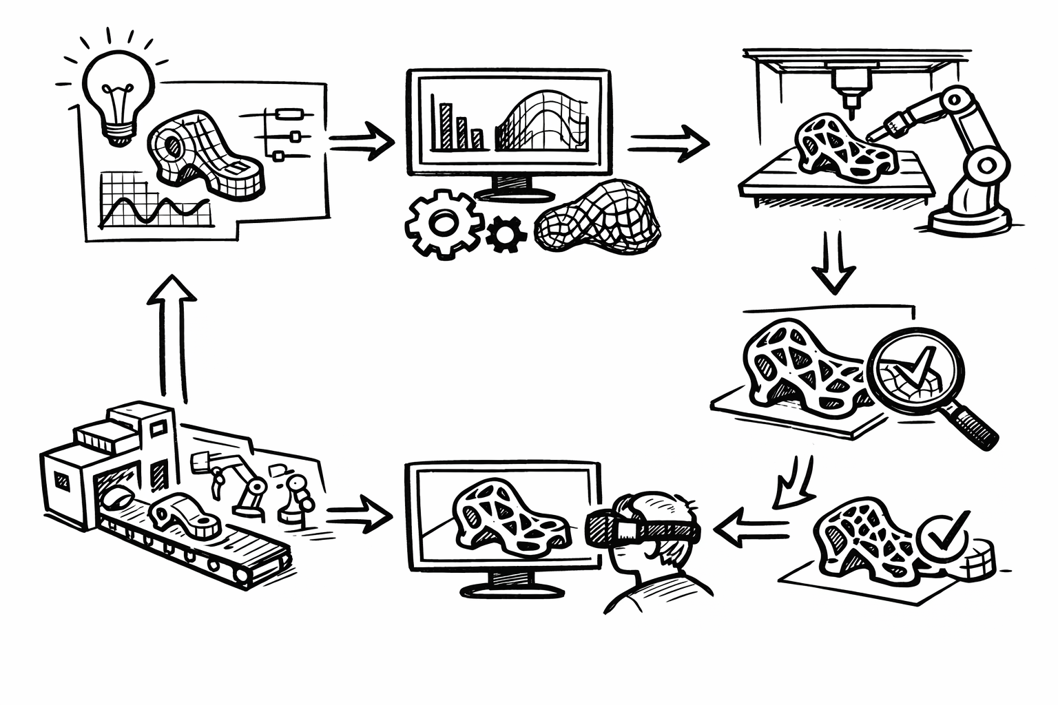


Modern design software makes it easy to move fast—sketch, iterate, render, optimize, and send geometry downstream in hours. The harder part is ensuring that the speed and freedom of exploration still produce outcomes that are manufacturable, verifiable, and repeatable. This article is a practical, advanced roadmap for connecting design intent to production constraints and measurable performance across CAD/BIM, computation, simulation, visualization, and additive manufacturing.
The central tension is persistent: creative velocity versus traceability, simulation fidelity, and the realities of production. Success is not “a great model” or “a convincing render.” Success is a workflow where changes propagate predictably, decisions are defensible, and the late-stage surprises that burn schedule and credibility are systematically reduced. In practice, that means repeatable workflows, measurable performance gains, and a design thread that stays intact from early intent to final verification.
Parametric intent as the “source of truth” (beyond simple feature trees)
Parametric intent is often misunderstood as a feature tree with named dimensions. In advanced practice, it is a resilient system: parameters, constraints, rules, and relationships that survive change without collapsing into rebuild errors or silent regressions. The goal is to represent not just geometry, but the logic for why geometry is the way it is—so downstream analysis, costing, documentation, and visualization can remain consistent as requirements evolve.
A robust “source of truth” has three characteristics:
- Resilience under change: modifications do not break unrelated regions or introduce unintended side effects.
- Semantic clarity: parameters encode meaning (load path depth, clearance class, fire rating) rather than ambiguous labels (d12, offset3).
- Downstream readiness: the same intent can drive simulation loads, material maps, manufacturing rules, and visualization configurations.
Constraint schemas: hierarchical guardrails and failure-friendly design
Constraints should behave like guardrails, not handcuffs. A common mistake is treating constraints as a way to “lock” a model into correctness; over time this yields brittle dependencies and fragile rebuild chains. Advanced constraint schemas emphasize hierarchy: define primary drivers (envelope, interface planes, datum systems), then allow subordinate features to adapt within that structure.
Failure-friendly constraint design is a deliberate strategy: you anticipate where change will happen and constrain accordingly. Examples include:
- Use reference geometry (skeleton curves/surfaces, master datums) to absorb topological changes while keeping interfaces stable.
- Prefer dimensioning to stable datums rather than edges/faces that may disappear after a fillet or boolean edit.
- Encode clearance and tolerance intent as parameters (e.g., “assembly_clearance_mm”) rather than hard-coded offsets.
Design variants via configuration spaces
Advanced parametric systems treat variability as a first-class feature. Instead of duplicating files for each size or option, you define a configuration space: an envelope of allowed relationships. In product design this looks like families and product platforms; in architecture it can be typologies and parameterized façade systems; in industrial equipment it can be interchangeable modules constrained by interface standards.
The key is to build configurations around invariants and interfaces. When done well, you can explore variants programmatically and still guarantee that the “edges” of your system—mounting points, access volumes, code clearances—remain valid.
Semantic naming and metadata tagging
Semantic naming is not aesthetic. It is the mechanism that lets intent propagate into automation. If a parameter is called “rib_pitch,” it can drive a lattice density; if it is called “thermal_contact_pressure,” it can drive boundary conditions; if a part is tagged “coating=anodized_typeII,” your renderer can assign physically based material values derived from a spec sheet rather than artist intuition.
At minimum, metadata should support:
- Simulation hooks (material model identifiers, load case mapping, contact pairs).
- Manufacturing rules (minimum wall, overhang thresholds, machining allowances).
- Visualization configuration (finish, colorway, LOD tier, “must-show” edges for QA).
Common failure modes and fixes
Most parametric breakdowns are predictable:
- Over-constrained models: conflicting constraints that suppress adaptability.
- Brittle dependencies: features referencing transient edges/faces.
- Circular logic: parameter A drives B which drives A through a chain of relations.
Effective fixes are structural, not cosmetic. Modularization is usually the turning point:
- Use skeleton models and derived parts to centralize primary datums and interface geometry.
- Establish explicit interface control documents (ICDs), even if informal, that define what “must not change” across modules.
- Partition the model so rebuild failures are localized and diagnosable rather than cascading.
The outcome to target is predictable, auditable change propagation that remains compatible with automation. If you cannot confidently answer “what changes if I modify this parameter?” your parametric system is not yet acting as a source of truth.
Generative + computational workflows: exploring solution spaces with accountability
Generative design is often presented as form finding: produce a dazzling field of options and pick one that “looks right.” In advanced workflows, generative systems are decision systems. They encode objectives, constraints, and governance so that outputs come with rationale, repeatability, and a clear path back to intent.
Objective functions and constraints: turning exploration into a decision system
An objective function can be a single scalar (minimize mass) or a multi-objective set (mass, stiffness, embodied carbon, cost, daylight autonomy, thermal comfort). What matters is explicitness: if it is not written down as a computed measure, it will be replaced by subjective preference under schedule pressure.
Constraints turn “interesting geometry” into viable geometry. Typical constraints include manufacturing limits (minimum feature, draft direction, tool access), code requirements (egress, structural factors), assembly rules (fastener access, insertion direction), and machine envelopes (build volume, robot reach).
A practical pattern is to separate:
- Hard constraints that must always pass (envelope, safety clearances, minimum thickness).
- Soft objectives that trade off (mass vs. stiffness vs. cost).
Toolchain patterns: node logic plus versionable code
Node-based computation (Grasshopper/Dynamo-style) is excellent for rapid assembly of geometric logic and for making dependencies visible. But long-lived workflows need versionable, diff-able logic. The most effective hybrid pattern is:
- CAD/BIM as the authoritative geometry container and interface definition.
- Node-based graphs to orchestrate geometry and data flow.
- Scripting (Python/C#) for algorithms, file I/O, and validation checks where textual code is easier to review and test.
This hybrid approach supports both agility and governance: designers can iterate visually while teams can review code changes and run automated checks.
Data structures for branching design studies
Once you move beyond a few manual configurations, you need structures that can represent “design branching” without chaos. Common strategies include design-of-experiments matrices (full factorial or fractional), graph-based representations of dependency and variation, and Pareto fronts for multi-objective trade-offs.
In practice, the workflow should produce:
- A parameter snapshot per candidate (so every result is reproducible).
- A computed metric set (mass, deflection, cost proxy, carbon proxy, etc.).
- A link to the exact computational definition version used to generate it.
Governance: version control, reproducibility, dependency locking
Accountability is what separates serious computational design from a pile of outputs. Version control should include not only scripts but also computational definitions and parameter snapshots. The goal is “diff-able logic”: when a definition changes, you can tell what changed and why it affected results.
Reproducibility becomes challenging when randomness is involved (stochastic solvers, sampling, evolutionary algorithms). Seed control and dependency locking are essential: the same inputs should generate the same outputs across machines and time. For larger organizations, containerized runs can eliminate “it worked on my computer” variation by pinning runtimes and libraries.
The outcome to target is a curated set of “best” candidates with traceable rationale—not simply a gallery of attractive forms. A good generative pipeline can answer: which constraints eliminated which options, which parameters drove the Pareto trade-offs, and what exact logic produced the selected candidate.
Simulation-driven development: multi-physics, uncertainty, and real-world correlation
Simulation becomes transformative when it shifts from late validation to early guidance. The maturation path is typically: reduced-order models in early exploration, then mid-stage FEA/CFD for credible design shaping, then late-stage detailed verification when interfaces and loads stabilize. The mistake is not using simulation “too little,” but using it too late and with assumptions that are never validated.
From reduced-order models to detailed verification
Reduced-order models (ROMs) can be fast enough to sit inside a generative loop: simplified beams, lumped thermal networks, surrogate models trained from sparse high-fidelity runs. They are not “less correct”; they are fit-for-purpose approximations that help teams avoid wasting time polishing geometry that violates physics.
As the design converges, you increase fidelity: contact definitions, detailed boundary conditions, nonlinearities, and refined meshes. At this stage, the objective is not only “pass/fail” but identifying which design levers still matter.
Material modeling beyond linear elastic
Advanced products and buildings rarely behave as linear elastic solids under perfect loads. Material realism matters, especially when you are using additive manufacturing, composites, polymers, or high-cycle fatigue conditions. Relevant extensions include:
- Anisotropy (direction-dependent stiffness/strength), common in printed parts and composites.
- Hyperelasticity and viscoelasticity for elastomers and time-dependent polymers.
- Fatigue modeling to avoid designs that pass static stress but fail in service.
The practical takeaway is that materials should not be a generic library selection. They should be linked to process and specification, ideally via metadata so that changing a process window updates simulation assumptions.
Contact, nonlinearities, buckling, and coupled physics
Many late-stage failures come from missing “nonlinear reality”: contact interfaces that slip, preload effects, geometric nonlinearities, and buckling sensitivity. Similarly, thermal-structural coupling can dominate outcomes in electronics enclosures, aerospace components, and additive manufacturing builds.
In high-consequence designs, treating coupled physics as a luxury is risky. A seemingly minor temperature gradient can alter clearances, shift contact pressures, and cascade into seal leakage or fastener loosening.
Meshing as a design decision
Mesh quality is not an implementation detail; it is a design decision that controls whether your simulation can be trusted. Adaptive refinement is powerful, but it does not replace convergence thinking. A defensible workflow includes mesh sensitivity checks and documented convergence criteria—especially near stress raisers, contact regions, and thin features.
When simulation is embedded in iterative design, you can formalize meshing rules tied to geometry metadata (thin-wall regions get targeted refinement; fillet radii below a threshold trigger local mesh density increases). This is one of the most direct ways to make simulation repeatable rather than artisanal.
Uncertainty and robustness: variability is the real environment
If your simulation assumes perfect geometry, perfect material, and perfect loads, the result is often an illusion of certainty. Robust design treats variability as part of the model. Sensitivity analysis identifies which parameters actually matter—the subset worth controlling tightly or monitoring in production.
Monte Carlo or Latin hypercube sampling lets you propagate variability through the system: manufacturing tolerances, load ranges, boundary-condition ambiguity, material property distributions. The output shifts from a single number to a distribution, which is far more actionable for design decisions.
The correlation loop: from test data to updated assumptions
Simulation becomes trustworthy when it is continuously correlated with reality. That means ingesting test data, calibrating uncertain parameters, and updating assumptions. Even without a full digital twin, a “digital twin-lite” approach can keep models aligned to measured behavior through periodic updates, especially for products with recurring production runs or long facility lifecycles.
The outcome to target is straightforward: fewer late-stage redesigns because simulation accounts for variability and is continuously corrected by test reality, not frozen as an optimistic snapshot.
Design for Additive Manufacturing (DfAM): from topology to build-ready geometry
Topology optimization and generative workflows can produce “optimal” shapes that are unprintable, uninspectable, or uneconomical to post-process. DfAM is the discipline of reconciling performance-driven geometry with build constraints, qualification requirements, and operational repeatability.
Build constraints that must inform the design loop
In powder bed and related processes, build constraints are not peripheral—they dictate cost, risk, and yield. Critical considerations include overhang rules and support strategy, thermal distortion, recoater collision risk, minimum feature sizes, lattice resolution, powder evacuation, and trapped volumes.
Designing without these constraints often leads to an expensive conversion phase where engineers “make it printable” and inadvertently ruin the performance the optimization promised.
Geometry strategies: implicit modeling and field-driven structures
Implicit modeling (signed distance fields, or SDFs) has become a practical method for DfAM because it naturally supports smooth blends, complex lattices, and robust booleans. It also allows you to drive geometry by fields: stress fields, thermal gradients, acoustic targets, or fluid flow requirements.
One powerful application is lattice grading tied to stress: density increases where loads demand it, and decreases elsewhere to save mass and reduce print time. Functional porosity can be tuned for weight reduction, thermal exchange, or acoustic damping—provided the lattice resolution and powder evacuation paths remain feasible.
Process-aware optimization: orientation, scan strategy, residual stress
Build orientation is not merely “what fits in the machine.” It influences surface quality, support volume, anisotropy direction, distortion risk, and inspection access. Scan strategy and residual stress can create warping that invalidates tight tolerances or induces cracking in sensitive alloys.
Process-aware optimization closes the loop: you incorporate orientation effects and residual stress predictions into the design stage rather than reacting after a failed build. Compensation methods such as scaling and inverse-warping can be applied based on predicted distortion, but they must be traceable and linked to a defined process window.
Qualification and repeatability: tying process windows to metadata
Printing a part once is not the same as producing it reliably. Qualification requires a scaffold: witness coupons, in-situ monitoring where available, and CT scanning where appropriate for internal features. The key systems insight is to link material allowables and process windows back to the CAD model’s metadata—so that a “material” is not just a name, but a qualified bundle of parameters (machine, powder batch constraints, heat treatment, inspection method).
The outcome to target is build-ready geometry that prints predictably, meets specification, and reduces post-processing burden. When DfAM maturity is high, the build file is a controlled derivative of the same intent model—not an ad hoc artifact that lives on someone’s workstation.
Product visualization as verification: real-time rendering, XR, and measurable communication
Visualization is often treated as a downstream deliverable for marketing. In advanced workflows, visualization is part of verification: it reduces ambiguity, reveals defects earlier, and creates measurable communication across engineering, manufacturing, and stakeholders.
Decision-grade visualization: physically based materials and revealing light
Physically based rendering becomes engineering-relevant when material parameters reflect real specifications: roughness tied to bead-blast finish, index of refraction aligned to a polymer grade, coatings represented with correct reflectance behavior. This improves not only realism but diagnostic clarity.
Lighting is equally critical. Certain lighting setups are designed not to flatter but to expose: reflection lines that reveal subtle waviness, grazing angles that show parting lines, and high-contrast environments that make surface transitions and tolerances legible. In short, you are using rendering as a visual inspection tool.
Real-time pipelines: USD/glTF, LOD, and instancing
For large assemblies or building-scale scenes, real-time pipelines are the only practical way to review decisions interactively. Efficient flows often rely on CAD-to-USD or CAD-to-glTF conversion with deliberate LOD strategies: keep high fidelity where it impacts decisions (interfaces, ergonomic touchpoints, seal surfaces) and simplify where it does not.
Instancing is a major lever for performance when repeated elements occur (fasteners, façade panels, seating, MEP components). When the visualization pipeline is connected to parametric metadata, outputs become configurator-ready: the same configuration space that drives engineering can drive visuals without duplicating logic.
XR and spatial review: AR fit-checks and VR sign-off
XR becomes practical when it is used surgically. AR can support fit-checks and installation sequencing by overlaying digital intent on physical context, revealing clashes, reach issues, or clearance violations before fabrication or site work. VR can accelerate ergonomics and maintainability reviews, allowing stakeholders to validate access paths, service operations, and line-of-sight constraints.
The key is to treat XR findings as engineering input, not as “experience.” Which leads to the most important capability: structured feedback.
Measurement and feedback: making visualization auditable
Verification-grade visualization uses checklists and structured capture. Visual QA can include reflection line continuity, edge continuity across blends, interference cues in assembly motion, and tolerance-critical transitions. Review comments should be captured as structured data—linked back to parameters and issue trackers—so they can be resolved systematically and traced to a change in the source of truth.
The outcome to target is measurable communication: visualization that reduces ambiguity, accelerates approvals, and closes the loop with engineering intent rather than existing as a parallel, manually curated narrative.
Conclusion
The integrated thesis is simple but demanding: parametric intent must act as the source of truth; computational exploration must be accountable and reproducible; simulation must guide design while embracing uncertainty and correlation; DfAM readiness must translate “optimal” geometry into build reality; and verification-grade visualization must function as an auditable decision tool.
The actionable takeaway is to treat every artifact—model, script, solver setup, result set, render, XR review—as part of a traceable system that can be audited, automated, and improved over time. When that system exists, creativity and speed do not have to be sacrificed; they become safer, more scalable, and far more likely to reach production without expensive surprises.
Also in Design News