
Your Cart is Empty


Embedded Simulation in CAD: From Late Validation to Real-Time Design Feedback
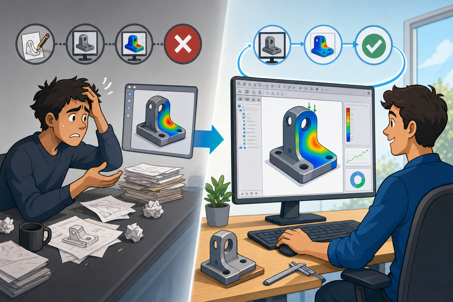


Embedded Simulation as a Shift from “Check Later” to “Design While Knowing”
The old loop: design first, discover consequences later
Mechanical design has traditionally followed a sequential loop in which geometry is created, handed off, tested virtually or physically, revised, and then tested again. A designer builds the initial CAD model around packaging constraints, manufacturing requirements, interfaces, and design intent. Once the concept looks complete enough, the model is exported to a simulation specialist or opened in a separate CAE platform. At that point, the geometry often needs preparation: small features are suppressed, gaps are repaired, fasteners are simplified, mid-surfaces may be extracted, and contact regions must be interpreted. Only after that cleanup can the analyst create a mesh, define loads, apply boundary conditions, choose materials, run the solver, and interpret the results. The output then returns to the design team as a report, a contour plot, or a set of recommendations. If the bracket bends too much, the housing overheats, or a vibration mode appears too close to operating speed, the CAD model changes and the process begins again. This workflow works, but it tends to place engineering knowledge after major design decisions have already hardened.
Why late validation makes change expensive
The greatest weakness of the traditional loop is not that it uses separate tools; specialist CAE environments remain indispensable for many forms of advanced analysis. The weakness is timing. When simulation happens late, even modest design changes can become expensive because geometry has already been detailed, assemblies have been checked, drawings may have started, suppliers may have been consulted, and prototype assumptions may already be in motion. A rib added to improve stiffness might interfere with a mating component. A thicker wall may change cooling time in injection molding or increase mass beyond a product requirement. A material substitution may affect cost, corrosion resistance, electromagnetic behavior, or additive manufacturing parameters. By the time virtual validation reveals a performance problem, the design space is already smaller than it was during concept development. This is why **embedded simulation inside CAD environments** is not merely a convenience feature. It changes when design teams receive feedback, moving performance insight into the stage where geometry is still flexible, constraints are still negotiable, and alternatives can be explored without organizational friction.
The new loop: model, simulate, revise, and understand continuously
Embedded simulation allows stress, thermal, modal, motion, fatigue, and basic fluid checks to be performed directly in or very near the design workspace. Instead of finishing a model and sending it away for evaluation, the engineer can ask questions while modeling: will this mounting ear deform under bolt preload, will this heat sink dissipate enough energy, will this arm vibrate near the motor frequency, will this linkage collide during travel, or will this enclosure wall oil-can under pressure? The point is not to produce the final certification analysis from a preliminary model. The point is to make performance visible while design intent is still forming. When used well, embedded tools support an iterative style sometimes described as **design while knowing**. Engineers can evaluate more concepts, reject weak ideas earlier, and focus specialist resources on the designs that deserve deeper scrutiny. This is especially powerful in additive manufacturing, lightweight structures, electronics packaging, and compact mechanisms, where small geometric changes can produce large variations in stiffness, temperature, vibration response, or manufacturability.
- CAD modeling remains the place where design intent, interfaces, dimensions, and manufacturability are defined.
- Embedded simulation provides quick feedback before the design is committed to expensive downstream work.
- Expert CAE remains essential for nonlinear behavior, complex contact, certification, advanced fatigue, multiphysics, and high-risk validation.
- Physical prototypes become more focused because fewer weak concepts reach the build stage.
Upstream analysis does not eliminate expert judgment
A productive way to understand embedded simulation is to treat it as a shift in engineering attention, not as a replacement for analysts. Expert CAE deals with detailed assumptions, solver selection, mesh convergence, nonlinear materials, transient events, contact complexity, fatigue spectra, fluid turbulence, manufacturing variation, and regulatory evidence. Embedded simulation is best suited for early decisions, comparative evaluation, and directional guidance. It helps answer whether option A is likely better than option B, whether a wall is obviously too thin, whether a resonance risk is emerging, or whether a cooling strategy deserves further work. This distinction matters because democratizing simulation without discipline can create false confidence. A beautiful stress plot is not automatically a valid engineering conclusion. Boundary conditions, contacts, load paths, mesh density, material models, and simplifications still matter. The value of embedded simulation is strongest when organizations pair usability with method: templates, review practices, known assumptions, and escalation rules that define when a quick CAD-based analysis must become a more rigorous CAE study.
What Makes Embedded Simulation Different from Traditional CAE
Live geometry creates a different simulation experience
The most important difference between embedded simulation and traditional CAE is its relationship to live CAD geometry. In a conventional workflow, the design model often becomes a snapshot that is exported, simplified, meshed, and studied separately. If the designer changes a fillet radius, rib orientation, wall thickness, or mounting hole location, the analysis model may need to be rebuilt or re-associated. Embedded tools reduce this separation by allowing simulation definitions to remain connected to the evolving model. When dimensions, features, materials, or assembly constraints change, the analysis can often update without recreating the entire setup. This makes “what if” exploration far more natural. An engineer can thicken a boss, move a gusset, change aluminum to glass-filled nylon, alter a screw pattern, or adjust a lattice region and immediately evaluate the performance direction. The result is not simply faster analysis; it is a more fluid relationship between **design intent and performance feedback**. Simulation becomes part of modeling thought, much like interference checking, mass properties, or draft analysis.
Simplified setup lowers the barrier to useful questions
Traditional CAE platforms are powerful because they expose extensive control over meshing, element types, constraints, contacts, solver settings, and post-processing. That depth is essential for expert work, but it can also discourage designers who only need an early answer. Embedded simulation tools typically use guided workflows that help non-specialist users define reasonable first-pass studies. They may offer preset load cases, automated meshing, built-in material libraries, simplified contact assumptions, recommended constraints, and visual result interpretation tools. A designer checking a machined bracket may not need to choose among numerous shell, solid, or higher-order element formulations for a preliminary comparison. They may need to know whether moving material from the center to the load path reduces maximum displacement and improves the factor of safety. The best embedded systems make that question approachable while still exposing enough assumptions to prevent misuse. Effective usability is not about hiding engineering reality; it is about guiding users through common decisions without forcing every early design review to become a specialist simulation project.
- Preset load cases speed up common evaluations such as gravity, pressure, torque, bearing loads, bolt loads, and thermal power input.
- Automated meshing allows quick solid mesh generation while still permitting refinement near stress concentrations or thin regions.
- Built-in material libraries reduce setup time and encourage realistic comparison among metals, polymers, composites, and printable alloys.
- Guided constraints help users avoid completely free bodies, overconstraint, or unrealistic fixed supports.
- Visual post-processing makes displacement, stress, temperature, mode shape, and flow trends readable inside the design environment.
Common capabilities now available inside design environments
The range of embedded simulation has expanded significantly. Linear static stress analysis is often the entry point because it helps evaluate strength and stiffness under small-deformation elastic assumptions. Thermal analysis is increasingly common for electronics housings, LED fixtures, power modules, battery enclosures, heat sinks, and compact consumer devices where packaging density creates heat management challenges. Modal analysis helps identify natural frequencies and mode shapes in vibration-sensitive brackets, motor mounts, frames, instrument supports, and rotating equipment. Motion simulation supports linkages, actuators, hinges, cams, robotics subsystems, and packaging mechanisms, especially when designers need to understand velocity, acceleration, torque, clearance, and timing. Basic CFD capabilities can estimate airflow paths, cooling behavior, pressure drop, fan performance, or fluid distribution in early product layouts. Fatigue tools may provide preliminary life estimates when material data and loading assumptions are suitable. None of these capabilities remove the need for advanced validation, but they broaden the number of performance questions a mechanical team can ask before committing to detailed engineering decisions.
Transparency matters as much as speed
The most mature embedded simulation workflows acknowledge that ease of use can be dangerous when it hides assumptions. A fixed support on a face may be convenient, but real mounting conditions may include bolt compliance, gasket compression, friction, bearing surfaces, or flexible mating parts. A clean linear stress result may ignore plasticity, large displacement, temperature-dependent material behavior, residual stress, or manufacturing defects. An automated mesh may miss a sharp stress concentration unless refinement is applied. A basic fluid model may produce useful airflow trends while still being unsuitable for detailed turbulence prediction or acoustics. Therefore, the ideal embedded simulation environment must balance accessibility with engineering transparency. Users should be able to see mesh quality, understand units, review contacts, inspect loads, identify singularities, compare stress and displacement, and distinguish numerical artifacts from meaningful results. Organizations that succeed with embedded simulation usually define practical rules: use it for ranking, screening, and early sizing; involve analysts when loads are uncertain, behavior is nonlinear, safety factors are tight, or the product requirement demands formal verification.
How Embedded Simulation Shortens Mechanical Design Iterations
Concept screening becomes a normal part of modeling
Mechanical teams often generate more ideas than they can fully develop. Without rapid feedback, concept selection may depend too heavily on intuition, prior experience, manufacturing preference, or visual confidence. Embedded simulation changes this by making concept screening fast enough to happen before detailed engineering begins. A team designing a lightweight bracket for additive manufacturing can compare a solid baseline, a ribbed machined-style version, a topology-inspired version, and a lattice-reinforced version while the interfaces remain constant. Instead of waiting until one option is fully detailed, the team can approximate load paths, apply realistic constraints, evaluate displacement and stress trends, and discard weak concepts before they consume prototype or analyst time. This is particularly valuable in additive manufacturing because design freedom can easily lead to geometry that looks sophisticated but performs poorly under real loads. Early simulation helps ensure that material is placed along force paths rather than merely arranged into visually complex forms. By the time a design reaches deeper analysis, it has already passed several performance filters.
Less handoff friction means fewer disconnected models
Handoffs between CAD and CAE are unavoidable in many advanced workflows, but every handoff introduces opportunities for delay and inconsistency. Files may need translation from one format to another. Assemblies may lose metadata, mates, materials, named selections, or feature history. Small sliver surfaces can create poor meshes. Geometry repair can consume hours before analysis even begins. Meanwhile, the designer may continue changing the original model, creating uncertainty about which version is being studied. Embedded simulation reduces this friction by keeping early analysis near the source model. Designers and analysts can discuss the same geometry, review the same dimensions, and agree on which simplifications are acceptable. Even when a design later moves into a specialist CAE platform, earlier embedded studies can improve the handoff by identifying critical load paths, sensitive features, likely boundary conditions, and regions requiring mesh attention. The objective is not to eliminate expert workflows but to ensure that when expert time is used, it is used on geometry that has already been refined through informed iteration.
- Fewer geometry exports reduce translation errors and duplicated cleanup work.
- Consistent source models help teams avoid analyzing outdated versions of a design.
- Early identification of sensitive regions guides later mesh refinement and validation effort.
- Shared visual results improve conversations between design engineers, analysts, manufacturing engineers, and product owners.
Parametric changes become performance experiments
One of the most practical advantages of embedded simulation is the ability to connect parametric modeling with immediate performance exploration. Engineers can see how wall thickness, rib placement, fillet size, hole spacing, mounting strategy, material choice, or internal structure affects stiffness, temperature, vibration, and mass. Consider an enclosure that deforms under screw preload. Without embedded analysis, the designer might simply thicken the entire wall, increasing weight, material cost, and molding cycle time. With embedded simulation, the designer can compare localized bosses, washer seats, rib networks, fillet transitions, different screw torque assumptions, and alternative plastic grades. The result may be a more efficient design that controls deformation without unnecessary material. Similarly, when evaluating heat dissipation in a compact device, an engineer can compare vent placement, heat sink fin spacing, interface contact area, internal air paths, and housing material before committing to industrial design tooling. The feedback does not need to be perfect to be useful; it needs to be timely, comparative, and good enough to guide the next design move.
Designers and analysts work at better levels of complexity
Embedded simulation changes collaboration by letting designers perform first-pass studies and allowing analysts to concentrate on the problems that genuinely require advanced expertise. In a less mature workflow, analysts may be asked to evaluate many weak or underdeveloped designs because no one else has the tools or confidence to perform preliminary checks. This can turn expert analysis teams into bottlenecks. In a better workflow, designers use embedded simulation to answer early questions and document assumptions. Analysts then review higher-value candidates, challenge boundary conditions, improve material models, assess fatigue, resolve nonlinear contacts, perform multiphysics analysis, or prepare certification-grade evidence. This division of labor raises the technical quality of both roles. Designers become more aware of load paths, stiffness, mode shapes, thermal gradients, and sensitivity to geometry. Analysts spend less effort explaining obvious failures and more effort on hard engineering questions. The collaboration also becomes more visual: instead of debating abstract concerns, teams can point to displacement patterns, hot regions, stress concentrations, or modal deflections directly in the model.
- Designers perform early stress, thermal, modal, motion, and airflow checks to guide geometry.
- Analysts focus on nonlinear materials, detailed contact, fatigue life, dynamic loading, multiphysics, and validation requirements.
- Manufacturing engineers assess whether simulated design improvements are compatible with machining, molding, casting, sheet metal, or additive manufacturing constraints.
- Project teams make decisions earlier because performance evidence appears during design reviews, not only after formal analysis cycles.
Practical outcomes across product development
The impact on product development can be substantial. Late-stage surprises decrease because obvious stiffness, strength, thermal, vibration, and motion problems are discovered before design freeze. Prototype costs fall because fewer physical builds are used merely to identify avoidable flaws. Engineering change cycles shorten because teams are not repeatedly waiting for external analysis feedback before making basic geometry decisions. Confidence improves because the design has been exposed to multiple performance questions throughout its evolution. For example, a motor mount in an electric drive assembly can be checked for vibration modes while bolt patterns and gussets are still flexible. A compact consumer device can be evaluated for heat accumulation before surface styling and internal packaging are finalized. A pressure-loaded enclosure can be tested for deformation before gasket compression and sealing strategy become expensive to change. A lightweight additive bracket can be optimized for material placement before print orientation, support strategy, and post-processing are finalized. Across these examples, the real advantage is timing: performance insight arrives early enough to influence design direction rather than merely approve or reject it.
Conclusion: Embedded Simulation Is Becoming a Core Design Capability
Simulation is becoming a native layer of design intelligence
Embedded simulation is changing mechanical design from a sequential process into a continuous feedback loop. Its greatest value is not only speed, although faster turnaround is important. Its deeper value is timing. Engineers receive performance insight while design intent is still forming, when a hole can be moved, a rib can be redirected, a material can be tested, or a mounting strategy can be reconsidered without triggering major rework. This makes simulation less of a final checkpoint and more of a native layer of design intelligence. The most effective teams will not treat embedded simulation as a shortcut around engineering discipline. They will treat it as a way to ask better questions earlier. Use it for early decisions, comparative studies, design direction, concept screening, and sensitivity exploration. Use advanced CAE for high-risk behavior, nonlinear response, complex fatigue, regulatory validation, mission-critical operation, and any situation where assumptions must be rigorously defended. The distinction is not embedded versus expert simulation; it is the right level of simulation at the right stage of design.
The next workflow will expect continuous feedback
As CAD platforms continue integrating AI, cloud computing, automated meshing, generative design, real-time solvers, and richer material intelligence, simulation will become less isolated from the daily act of modeling. AI-assisted setup may suggest loads, identify suspicious constraints, flag mesh problems, or compare results against known design patterns. Cloud solvers may allow multiple geometry variants to run in parallel without slowing local modeling work. Automated meshing will continue improving for thin walls, lattice structures, contact regions, and additive manufacturing geometries. Real-time solvers will make certain stress, motion, thermal, and fluid approximations feel as immediate as dragging a feature dimension. These developments will raise expectations. Future mechanical design reviews may not accept geometry without at least preliminary evidence of stiffness, thermal behavior, vibration risk, manufacturability, and mass efficiency. The central question will no longer be, “When should we simulate?” It will increasingly become, “Why would we ever design without simulation feedback?” For teams building complex products under compressed schedules, embedded simulation is moving from optional productivity feature to core engineering capability.
Also in Design News






