Your Cart is Empty


Design Software History: Shipbuilding Software History: From Lofting Floors to Model-Based Marine CAD


From Lofting Floors to Early Computer Drafting
Why Ships Stretched the Limits of Early Design Technology
Shipbuilding became one of the first industries to expose the limits of ordinary drafting because a vessel is not a single machine, a building, or a set of isolated drawings; it is a floating industrial system whose geometry, structure, machinery, services, procurement, and production sequence must all agree. A large merchant ship, naval combatant, tanker, cruise ship, or offshore support vessel contains very large assemblies, compound curved hull surfaces, thousands of steel plates, miles of piping and cable, and dense machinery spaces where access, maintainability, safety rules, and classification requirements are inseparable from geometry. Before computers, shipyards had to coordinate naval architects, structural draftspersons, pipe designers, outfit planners, electrical teams, classification surveyors, purchasing departments, and production supervisors through drawings, lofting data, tables, and shop instructions. Unlike automotive or aircraft design, shipbuilding also had to account for immense physical scale and heavy fabrication: decks, bulkheads, shell plates, stiffeners, brackets, foundations, ladders, ventilation ducts, tanks, and machinery foundations had to be defined in a way that could be cut, bent, welded, inspected, painted, transported, and assembled into blocks. This made ship design software unusually demanding from the beginning, because the data was never only about shape. It also carried responsibility for stability, strength, weight, center of gravity, class compliance, material ordering, work packaging, and the sequence by which steel became a ship.
- Ships required software to manage curved hull forms and massive steel structures at the same time.
- Every design decision affected classification approval, procurement, production labor, and installation access.
- The scale of ship assemblies demanded early links between geometry, calculation, and manufacturing data.
The Mold Loft as the Original Geometric Modeling Environment
Full-Scale Lines, Fair Curves, and Craft-Based Precision
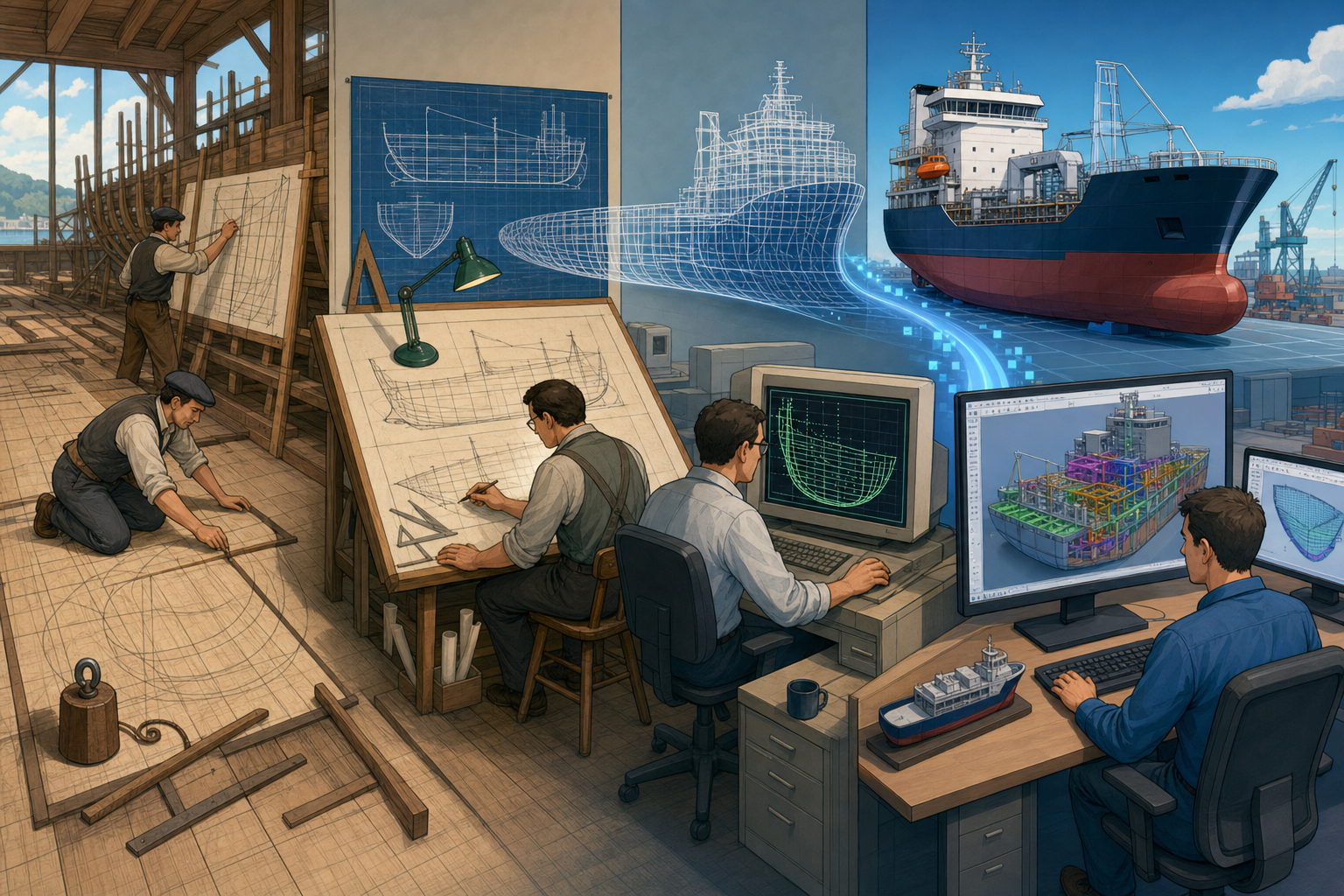
Before digital shipbuilding, the mold loft was a remarkable analog computing environment. Shipyards drew the hull lines at or near full scale on large loft floors, using battens, weights, splines, templates, and skilled judgment to transform naval architects’ offsets into fair, buildable geometry. The work was more sophisticated than simple drafting: loftsmen interpreted body plans, sheer plans, half-breadth plans, frame sections, waterlines, buttocks, and diagonals, then corrected inconsistencies so that the hull surface became smooth, manufacturable, and structurally coherent. Manual fairing was central because even small discontinuities in hull form could produce hydrodynamic penalties, fabrication errors, unfair plating, or misaligned frames. The output of lofting was practical geometry: templates for frames and plates, bevel information, expanded shell plate shapes, and reference data for the yard. Parallel to this geometric work, paper drawings defined frames, bulkheads, decks, tanks, foundations, piping, ventilation, electrical trays, accommodation outfitting, and equipment arrangements. The pre-digital workflow was therefore not primitive; it was an integrated craft-and-engineering system. Its weakness was that every revision propagated slowly and dangerously through layers of drawings, loft data, purchasing lists, and shop instructions. When a compartment changed, the effect might ripple into pipe routes, brackets, cable penetration locations, ventilation trunks, access openings, coating areas, and weight calculations. This is precisely why early computerization in shipbuilding did not begin as merely a drafting convenience. It emerged as a response to the difficulty of maintaining consistent geometry across an object too large and too interdependent for paper alone.
Mainframes, Hydrostatics, and the First Digital Hull Definitions
Mathematics Replaces the Purely Drawn Line
In the 1960s and 1970s, large naval yards, commercial shipyards, research laboratories, and classification-linked technical communities began using mainframe computers for calculations that had previously consumed extensive manual effort. Early marine computing focused on hull definition, hydrostatic calculations, stability assessments, displacement curves, sectional area curves, resistance estimates, and eventually numerical control information for steel cutting. The movement from drawn lines to mathematical hull description was historically important: a hull could now be represented by coordinates, curves, surface patches, offsets, and algorithms rather than only by ink, pencil, and loft-floor interpretation. This did not eliminate lofting immediately, but it changed the authority of the design definition. Once numerical hull data could drive calculations and manufacturing, the computer began to serve as a shared source for engineering and production. Naval organizations and industrial yards with sufficient capital were early adopters because the payoff was significant: fewer repeated calculations, more reliable offsets, better plate expansion, and the opportunity to feed numeric data to profile cutters and plate-burning machines. Classification societies such as Lloyd’s Register, Det Norske Veritas, American Bureau of Shipping, and Bureau Veritas also influenced the software environment by formalizing strength, stability, subdivision, and safety expectations that design data had to satisfy. At the same time, early CAD/CAM suppliers serving marine, offshore, and heavy industrial markets recognized that shipyards needed more than electronic drawing boards. They needed systems that could support curved steel, regulated structures, manufacturing tolerances, and enormous quantities of production information.
- Mainframes supported hydrostatics, stability, displacement, and early hull geometry management.
- Numerical control data helped connect digital definitions to plate cutting and fabrication.
- Classification societies shaped the computational requirements behind marine design software.
Why General-Purpose CAD Was Never Enough
The Ship as a Distributed Industrial Plant
General-purpose CAD packages improved drafting productivity, but shipbuilding demanded a deeper information model because a ship is not just a mechanical product scaled up. A ship hull contains curved surfaces, but the vessel also behaves like a steel building, a power plant, a hotel, a logistics platform, a fluid-handling network, and a regulated safety system. Structural design, piping, HVAC, electrical distribution, machinery installation, accommodation, cargo handling, fire protection, lifesaving systems, and access routes all compete for space across decks, compartments, voids, tanks, and machinery rooms. In a dense engine room, a pipe route is not merely a line in space; it has insulation, flanges, supports, spool breaks, welds, valves, access envelopes, pressure class, material codes, installation sequence, and maintenance clearance requirements. Similarly, a bracket or stiffener is not simply geometry; it belongs to a structural system with scantling rules, welding requirements, plate orientation, cutouts, nesting implications, and weight consequences. Production planning is also deeply tied to geometry because ships are assembled from blocks, panels, decks, bulkheads, units, and zones, often with pre-outfitting performed before erection. Ordinary CAD could draw these things, but drawing them was not enough. The shipyard needed software that understood relationships among parts, not just shapes. This drove the emergence of specialized marine CAD/CAM, where the model became a production database that could generate drawings, parts lists, NC cutting files, spool isometrics, installation documents, and planning data from a coordinated representation of the vessel.
FORAN, TRIBON, NAPA, and the Rise of Dedicated Marine Platforms
Specialized Systems Built Around Shipyard Reality
The rise of dedicated shipbuilding CAD/CAM systems marked a decisive break from the idea that marine design could be handled by generic drafting tools alone. FORAN, developed by the Spanish engineering company SENER, became one of the landmark integrated ship design and production platforms, supporting hull forms, structural modeling, outfitting, drawings, reports, and manufacturing outputs. TRIBON, associated with Kockums Computer Systems in Sweden and later absorbed into AVEVA Marine, became deeply influential in production-oriented shipbuilding, especially through its handling of structure, outfitting, pipework, and manufacturing data. NAPA, developed in Finland and closely associated with the Finnish naval architecture and shipbuilding community, became highly significant for naval architecture calculations, stability, loading conditions, hydrodynamics, and design-stage decision support. ShipConstructor, later developed under SSI in Canada, became known for production-oriented workflows and its integration with AutoCAD-based environments used by many smaller and mid-sized yards. These systems succeeded because they incorporated marine concepts as native objects: plates, seams, stiffeners, profiles, decks, blocks, compartments, pipe spools, penetrations, foundations, and equipment. Their technical advances covered digital hull fairing, plate development and nesting, structural modeling, pipe routing, spool definition, weight and center-of-gravity calculations, and generation of production drawings and NC cutting data. They also responded to the cultural reality of shipyards, where design evolves under pressure from owners, class, suppliers, production constraints, and late equipment changes. A successful shipbuilding system therefore had to support controlled change, not just beautiful geometry.
- FORAN helped establish integrated ship CAD/CAM as a complete production workflow.
- TRIBON became a major reference point for structure, outfitting, and manufacturing integration.
- NAPA strengthened the computational side of naval architecture, stability, and hydrodynamics.
- ShipConstructor / SSI emphasized practical production deliverables for shipyards using familiar drafting ecosystems.
From Drawings as Documents to Models as Production Databases
The Database Becomes the Yard’s Working Memory
The most important change introduced by specialized marine CAD/CAM was not simply faster drawing production; it was the gradual replacement of drawings as the primary design authority with structured models that behaved as production databases. In the older workflow, a drawing documented intent, and separate departments interpreted that intent for procurement, lofting, cutting, bending, assembly, welding, and installation. In the model-based workflow, geometry and attributes could be reused directly across disciplines. A structural panel could produce part drawings, plate nests, profile lists, weld information, assembly drawings, block weight estimates, and planning reports. A pipe system could generate spool drawings, material takeoffs, support locations, penetration requirements, and installation sequence information. This made earlier detection of clashes between structure, piping, cable trays, HVAC, equipment, and ladders vastly more practical. It also improved material takeoffs, because quantities no longer had to be estimated only from manually interpreted drawings. In shipbuilding, even a modest percentage error in steel, pipe, cable, insulation, or paint can have significant cost and schedule consequences. The database concept also helped manage weight and center of gravity, two quantities critical to vessel stability, performance, fuel consumption, and regulatory approval. A ship is sensitive to distributed weight: moving machinery, changing insulation thickness, adding cable trays, or substituting pipe materials can affect trim, stability margins, and payload. By making product information computationally accessible, marine CAD/CAM software allowed design teams to treat the vessel as a controlled engineering dataset rather than an accumulation of disconnected documents.
The Shift from Two-Dimensional Drafting to Coordinated Three-Dimensional Models
Spatial Coordination Before Steel Was Cut
The movement from 2D drafting to coordinated 3D product models fundamentally changed the way shipyards understood space. Hulls, compartments, decks, machinery spaces, structural blocks, outfitting zones, and pipe systems could be viewed and checked in shared three-dimensional environments before steel was cut or equipment arrived at the yard. This was especially important because ship spaces are often dense, irregular, and unforgiving. Engine rooms, pump rooms, offshore modules, LNG processing spaces, naval machinery compartments, and cruise ship service areas contain equipment with maintenance envelopes, hot surfaces, insulation, structural interferences, escape routes, lifting paths, and strict safety separations. Two-dimensional drawings could represent these conditions, but they required expert mental reconstruction and left too much room for interpretation. 3D modeling made spatial conflict visible. Clash detection became essential, not as a convenience but as a risk-control mechanism. A pipe passing through a stiffener, a ventilation duct blocking a hatch, a cable tray conflicting with a valve removal path, or a ladder obstructed by a support bracket could now be detected before fabrication rather than during installation. Visualization also improved communication among disciplines. Owners, class surveyors, subcontractors, equipment suppliers, and production teams could understand arrangements more easily through model reviews than through stacks of plans and sections. The result was not the elimination of drawings, but a shift in their role: drawings increasingly became generated views, reports, and work instructions derived from an underlying model whose consistency mattered more than the individual sheet.
- 3D environments made dense machinery spaces easier to inspect and coordinate.
- Clash detection reduced late rework in structure, piping, HVAC, and equipment installation.
- Model reviews improved communication between shipyards, owners, suppliers, and classification participants.
The Influence of CATIA, ENOVIA, NX, Teamcenter, AVEVA, and Autodesk
Marine Software Learns from Aerospace, PLM, and Plant Design
The modernization of shipbuilding software was influenced by broader developments in CAD, CAM, CAE, and product lifecycle management. Dassault Systèmes CATIA, originating in the aerospace world and shaped by the legacy of Dassault Aviation’s complex surface and assembly requirements, demonstrated how advanced 3D product modeling could manage highly complex engineered products. CATIA, together with ENOVIA, influenced thinking about configuration control, product structure, and lifecycle data management, all of which became relevant to sophisticated naval and commercial ship programs. Siemens NX and Teamcenter brought strong capabilities in mechanical design, manufacturing integration, simulation workflows, and enterprise product data management. These systems appealed to organizations that wanted tighter links between engineering authoring tools, manufacturing planning, supplier data, and configuration control. AVEVA, with roots in the Cambridge-originated plant design technology ecosystem and later acquisitions including important marine assets, became highly influential in large industrial, offshore, process plant, and marine projects. Its tools reflected the fact that many ships and offshore structures resemble floating industrial plants, with extensive piping, equipment, instrumentation, electrical, and structural coordination. Autodesk tools, particularly AutoCAD-based workflows, remained important in smaller yards, design offices, subcontractor networks, and production-driven environments where DWG familiarity, customization, and local drafting practices mattered. The result was a heterogeneous software landscape. Shipyards rarely used one system in isolation; they combined naval architecture tools, hull and structure systems, plant design platforms, mechanical CAD, document management, scheduling, ERP, and class submission processes. This diversity improved capability but also intensified the need for interoperability and disciplined data management.
Block-Based Construction and the Digital Shipyard
Software Aligns Geometry with Production Sequence
Modern shipbuilding increasingly depends on block-based construction, in which large prefabricated modules are assembled from panels, subassemblies, decks, bulkheads, structural units, and outfitted zones before final erection in dock or on the building berth. This production philosophy changed the requirements for software because the model had to support not only the final ship configuration but also the intermediate states through which the ship would be fabricated. A block might be built upside down for welding efficiency, pre-outfitted with pipe spools and cable trays, painted before erection, transported by heavy-lift equipment, and joined to adjacent blocks with surplus material allowances and weld access constraints. Software helped coordinate structural blocks, outfitting zones, pipe spools, foundations, access openings, and installation sequences. The digital model became a coordination hub for distributed subcontractors, equipment suppliers, and production planners who needed to know what could be installed when, in which orientation, with what lifting path, and with which neighboring systems already in place. This was a profound expansion of CAD’s role. The model was no longer only a representation of the completed vessel; it became a planning instrument tied to work breakdown structures, material availability, procurement packages, labor estimates, production zones, and quality checks. Digital shipyards used 3D models, scheduling systems, nesting software, ERP platforms, and document control systems to reduce the uncertainty that traditionally surrounded large fabricated products. The best marine software therefore had to understand production logic: a stiffened panel, a block boundary, a pipe spool, or a machinery foundation had meaning because it participated in the yard’s method of building.
- Block-based construction required models that represented fabrication stages, not only final geometry.
- Pre-outfitting depended on coordination among structure, pipe, electrical, coatings, and access planning.
- The digital shipyard linked CAD data to work packages, procurement, scheduling, and quality control.
Interoperability and the Limits of Neutral Geometry
Why a Ship Object Is More Than Its Shape
Interoperability has been one of the most persistent challenges in shipbuilding software because ship models contain richer information than most neutral geometry formats can reliably carry. Legacy marine formats, proprietary databases, STEP, IGES, DWG, and other exchange mechanisms have all played roles in moving data between naval architecture tools, structural systems, plant design platforms, mechanical CAD, subcontractor environments, classification review workflows, and production systems. However, the central difficulty is that a pipe, bracket, stiffened panel, penetration, foundation, or equipment item is more than a surface or solid. A pipe has specification, pressure class, insulation, support rules, spool breaks, fabrication allowances, test requirements, line numbers, and connection logic. A stiffened panel has plate thickness, grade, orientation, seams, profiles, welding standards, cutouts, weight, nesting behavior, and block affiliation. A bracket may carry rule-based purpose, associated members, manufacturing treatment, and installation context. When these objects are converted into neutral geometry, much of their shipbuilding intelligence can disappear. The receiving system may see cylinders, plates, solids, or curves, but not the production consequences embedded in the original model. This is why shipyards often relied on carefully governed data exchange processes, agreed modeling conventions, naming standards, attribute mappings, and controlled review models rather than expecting perfect round-trip interoperability. The broader standards community, including ISO STEP efforts and marine data modeling initiatives, helped address parts of the problem, but shipbuilding remains difficult because the same object must satisfy design, analysis, procurement, class, production, installation, operation, and maintenance needs. The data is multidimensional, and no simple file translation can preserve every local rule and workflow assumption.
From Computer-Aided Design to Lifecycle Information
The Ship Model Extends Beyond Delivery
The historical arc of shipbuilding software is best understood as an expansion of responsibility. Manual lofting gave way to computer-aided hull definition, hydrostatic calculation, and numerical control data. Drafting systems evolved into specialized shipbuilding CAD/CAM platforms that linked hull fairing, structure, outfitting, pipe routing, plate nesting, spool production, weight control, and manufacturing documentation. Three-dimensional product models then became central to modern shipyard operations, connecting engineering to production planning, procurement, subcontractor coordination, and quality control. The distinctive nature of shipbuilding software lies in its combination of naval architecture, mechanical design, plant design, structural engineering, logistics, regulatory compliance, and manufacturing execution. In few industries does a single model need to serve so many communities with such different expectations. A naval architect may ask the model for displacement and stability implications; a structural engineer may ask for scantlings and load paths; a pipe designer may ask for routing and spoolability; a planner may ask for block sequence; a buyer may ask for material quantities; a class surveyor may ask for compliance evidence; an operator may ask for maintainable asset information. This is why the ship model is not merely a visualization asset. It is a production and lifecycle database whose value depends on trustworthy relationships among geometry, attributes, documents, calculations, and organizational decisions. The more complete the model becomes, the more it resembles the vessel’s digital memory: a structured record of what was intended, approved, purchased, fabricated, installed, tested, and eventually maintained throughout service life.
Digital Twins, Automation, and the Future of Model-Based Shipbuilding
The Next Layer of Intelligence
Current and future directions in shipbuilding software extend the model from design and construction into operation, maintenance, simulation, and continuous improvement. Digital twins for vessel operation can connect design data with sensor information, maintenance records, equipment condition, fuel consumption, emissions performance, structural health monitoring, and class-related inspection history. Cloud collaboration is also becoming more important as shipyards, suppliers, owners, classification societies, design agents, and production partners work across different geographies and time zones. The difficulty is not only sharing files; it is managing permissions, model maturity, configuration states, review comments, supplier revisions, and approval evidence without losing trust in the authoritative dataset. Simulation-driven design is increasingly tied to energy efficiency and emissions reduction, especially as the maritime sector responds to decarbonization pressure, alternative fuels, hull-form optimization, wind-assist technologies, battery systems, hybrid propulsion, and stricter reporting regimes. Automation, rule-based design, and AI-assisted clash detection are natural extensions of the long historical trend: shipbuilding software has always tried to reduce the cost of discovering conflicts late. AI may help classify clashes by severity, recognize repetitive routing patterns, suggest bracket arrangements, predict producibility issues, or compare model behavior against yard standards, but it will be most useful when embedded in disciplined engineering data rather than treated as a replacement for domain expertise. The central insight is that shipbuilding software evolved slowly because ships are among the most complex engineered products ever made. That same complexity made shipbuilding one of the richest proving grounds for model-based design, where geometry, calculation, regulation, production, and lifecycle knowledge must finally converge.
Also in Design News