Your Cart is Empty
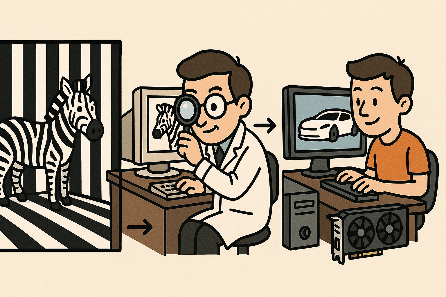
Design Software History: From Stripe Rooms to GPUs: The Evolution of Zebra Highlight Analysis and Class‑A Fairing


Introduction
From studio light tunnels to analytical highlights
The visual language of smoothness in industrial design once lived entirely in fluorescent tubes, glossy clay, and a designer’s practiced eye. Today, that language is encoded in software as zebra and highlight lines, curvature maps, and continuity analyzers that designers and engineers take for granted in Class‑A surfacing and beyond. The journey from physical “stripe rooms” to GPU‑accelerated interrogation tools is more than a story of digitization; it is the convergence of studio craft, mathematical formalization, and industrial systems engineering. It explains why a seemingly simple highlight kink can derail a launch and how a numerical continuity threshold can embody a brand’s idea of quality. This article traces that arc: the physical lineage of light‑based scrutiny, the mathematics that made fairness computable, the industrialization of interrogation through tools like ICEM Surf and Alias, and the algorithmic and workflow details that make modern zebras meaningful rather than mere cosmetics. Along the way, we connect names—Pierre Bézier, Paul de Faget de Casteljau, Gerald Farin, Malcolm Sabin—with kernels and GPUs, and we examine how aesthetics now cohabits with manufacturability metrics. The result is a compact history and a practical lens on why highlight analysis remains indispensable whenever form, light, and perception define the product.
Origins: light, lines, and curvature as design judgment
Physical lineage: stripe rooms, light tunnels, and clay practice
Before a pixel ever simulated a reflection, the auto studios of GM, Ford, Chrysler, and European coachbuilders such as Pininfarina, Bertone, and Italdesign Giugiaro used literal lines of light to expose imperfection. Long corridors—“light tunnels” or “stripe rooms”—arrayed fluorescent tubes across walls and ceilings. Designers rolled full‑scale clay mockups through these environments to observe how stripes flowed across fenders and beltlines. Any ripple or misalignment popped instantly as a break in continuity. This optical practice birthed the digital zebra: synthetic reflections that mimic tube arrays to reveal subtle surface defects.
Equally formative were clay “fairing” techniques. Modelers used wooden battens—flexible strips pinned to section points—to lay out fair curves and guide clay application. The batten’s elastic equilibrium embodied a minimization of bending energy; in effect, the batten sought a smoothness akin to mathematical thin‑plate energy. That intuition carried into digital algorithms: when engineers later spoke of “fairing a curve” or “relaxing a patch,” they were translating a tactile practice into computational objectives. Common studio tools included:
- Stretched tape lines and highlight gloss coats to exaggerate specular cues on clay.
- Template sweeps and milling bucks to verify left‑right symmetry under stripe lighting.
- Hard points and section sticks to anchor designers’ intent while allowing fairing between constraints.
These environments and tools operationalized a central idea: beauty and quality could be audited by how light travels. Digital highlight analysis did not invent that premise; it inherited and amplified it.
Mathematical foundations: curves, continuity, and fairness energies
The leap from craft to computation required representations that supported continuity measurement and controlled smoothness. At Renault, Pierre Bézier formalized polynomial splines now bearing his name, while at Citroën, Paul de Faget de Casteljau developed recursive evaluation (later popularized as de Casteljau’s algorithm) to robustly compute Bézier curves and surfaces. Industrial adoption accelerated when Carl de Boor and M. J. D. Powell advanced B‑spline theory and the Cox–de Boor algorithm delivered stable evaluation of nonuniform splines, paving the path to NURBS—nonuniform rational B‑splines that unified conics and freeform under one roof.
With NURBS, continuity became programmable. Engineers distinguished positional continuity (G0 / C0), tangency (G1 / C1), curvature (G2 / C2), and higher orders (G3/G4). Class‑A studios elevated these into quality gates, demanding G2 or G3 across key joints. Metrics of “fairness” emerged from both geometry and perception:
- Principal curvature, Gaussian and mean curvature maps to localize bending behavior.
- Isophotes (constant‑intensity lines) versus reflection lines, the latter more faithful to perceived gloss.
- Energy functionals like thin‑plate and Willmore integrals, operationalizing the batten’s bending logic.
- Perceptual shape descriptors from Jan Koenderink and Andrea van Doorn, notably shape index and curvedness, bridging differential geometry with human judgment.
This mathematics allowed software not just to draw a curve, but to interrogate and optimize it against quantifiable aesthetic and functional criteria—transforming subjective studio calls into reproducible analysis.
Early academic voices that shaped practice: from theory to studio habits
Several academics profoundly influenced how industry thinks about fairness. Gerald Farin codified curve/surface interrogation and fairing techniques that appeared in early high‑end systems. Malcolm Sabin advanced smoothness via Powell–Sabin splines and contributed to understanding G‑continuity across irregular networks, crucial for real‑world patch layouts. David Meek and John Walton explored monotone curvature (MC) curves, showing why visually pleasing transitions often exhibit monotonic or smoothly varying curvature. Later, Hiroyuki Yoshida and Takashi Saito introduced log‑aesthetic curves (LACs), whose logarithmic curvature graphs are straight lines; these curves capture the “effortless” feel of spirals and fillets beloved in transportation and consumer design.
These contributions penetrated tooling as:
- Curvature combs and porcupines that visualize κ and dκ/ds to guide fairing edits.
- G‑continuity solvers that adjust control points or weights to hit specified G2/G3 across patch boundaries.
- Semi‑automatic fairing routines minimizing curvature variation or thin‑plate energies while honoring hard constraints.
Crucially, their work encouraged designers to read curvature the way modelers once read tape lines—embedding a shared vocabulary so that “clean highlights,” “no S‑bend in the comb,” or “G2 within 0.05 mm equivalent” all point to the same underlying geometric health.
Industrialization of shape interrogation in Class‑A surfacing
1980s–1990s toolchains: ICEM Surf, Alias, and the OEM backbone
By the mid‑1980s, highlight analysis became a system capability, not a boutique research demo. ICEM Surf (by ICEM Systems, later Dassault Systèmes in 2007) set the Class‑A benchmark. It offered reflection lines, highlight lines, curvature maps, and robust G‑continuity solvers aligned with OEM release processes. ICEM’s interface spoke the studio’s language, and its numerics respected the realities of panel gaps, shut lines, and tooling splits. In parallel, Alias Research (founded 1983; later Alias/Wavefront; acquired by Autodesk in 2005) popularized StudioTools—now Autodesk Alias—across transportation and consumer electronics. Features such as zebra, isophotes, porcupines, and “diagnostic shading” gave designers immediate visual feedback as they pulled CVs and tweaked weights.
Meanwhile, integrated CAD platforms absorbed Class‑A ideas to serve downstream engineering. Unigraphics (now Siemens NX) and CATIA (from CADAM/CATIA V4/V5 under Dassault Systèmes) introduced highlight shading and continuity analyzers that dovetailed with solid modeling, drafting, and PLM. SDRC I‑DEAS made “highlight shading” a familiar step in OEM pipelines, binding industrial design and engineering within one data backbone. This integration mattered because highlight quality must survive:
- Topological edits—fillets, offsets, and draft transitions—that can inject inflections.
- Parametric updates—dimensional changes propagate and must preserve G2/G3 where specified.
- Manufacturing prep—split lines, die draw directions, and relief features that alter perceived highlights.
As these systems matured, “Class‑A” stopped being a mysterious art and became an enterprise capability, complete with templates, tolerance gates, and release sign‑offs tied to highlight inspections.
Mid‑range and open ecosystems: democratizing highlight literacy
Throughout the 1990s and 2000s, mid‑range mechanical CAD adopted highlight tools once reserved for high‑end surfacing. Pro/ENGINEER (now PTC Creo), SolidWorks (Parasolid kernel), Autodesk Inventor (ACIS kernel), and later Fusion 360 brought zebra shaders, curvature graphs, and draft/undercut analysis into mainstream workflows. While their initial sophistication lagged high‑end systems, they normalized the habit of checking highlights, especially in plastics where draft and wall thickness interact with perceived fairness.
Rhinoceros (Robert McNeel & Associates) further democratized analysis with CurvatureGraph, Zebra, and EMap (environment maps). The Virtual Shape Research (VSR) plug‑ins elevated Rhino toward Class‑A through advanced continuity tools until Autodesk acquired VSR in 2013 and folded technology into Alias. On the open side, OpenCASCADE enabled implementations of curvature and isophote analysis; numerous niche tools for marine, footwear, and lighting built on it to deliver specialized interrogation.
Two shifts amplified this democratization:
- Widespread GPU shading made interactive environment mapped highlights standard, closing the gap between model space and visual intuition.
- Reverse engineering pipelines—thanks to affordable scanning—pushed curvature interrogation onto meshes and point clouds, not just NURBS.
The net effect was cultural: highlight literacy spread beyond automotive studios to consumer goods, medical devices, and even architecture, where facade reflections and daylighting now benefit from the same diagnostic thinking.
Surface representation shifts: NURBS maturity, T‑splines, and SubD in CAD
As NURBS matured, toolmakers refined interface and solvers to deliver reliable G2/G3 continuity across complex patchwork. However, the desire for more sculptural flexibility and topology‑friendly modeling spurred alternatives. T‑splines, pioneered by Thomas W. Sederberg and colleagues, allowed local refinement without global CV proliferation. Autodesk’s 2011 acquisition brought T‑spline technology into Alias and Fusion 360, blending NURBS precision with SubD‑like agility. Subsequently, SubD modeling gained a formal place in industrial CAD—Rhino SubD and Alias SubD—shifting interrogation challenges to the limit surface.
Highlight analysis had to evolve accordingly. With SubD and T‑splines, curvature continuity is not simply a matter of shared knot vectors; it depends on subdivision stencils and extraordinary vertices. To maintain clean zebras, tools introduced:
- Limit‑surface curvature evaluation and combs directly on SubD cages.
- Crease/radius controls mapped to predictable G‑states at the limit.
- Hybrid workflows—convert SubD blocks to NURBS patches for release, then verify G2 using traditional analyzers.
These representations did not displace NURBS in release‑critical areas, but they broadened exploration. Designers could sketch complex character lines and tension surfaces quickly, then progressively “harden” them into Class‑A, with highlight diagnostics guarding the hand‑off between sculpt and spec.
Algorithms, implementations, and workflows that made “zebra” meaningful
What’s computed: from curvature combs to shape index histograms
Meaningful zebras arise from rich underlying interrogation. On curves, systems compute curvature combs (plotting κ perpendicular to the curve), curvature variation dκ/ds, and fairness energies such as the integral of κ² or penalties on |dκ/ds|. Designers often target clothoids (Euler spirals) and log‑aesthetic curves for transitions because their curvature changes linearly or exponentially with arc length, which reads as visually effortless. Practical curve tools expose:
- Interactive control of CV weights and knot spacing to steady combs.
- Numerical gates on max/min κ and bounded dκ/ds to avoid “S‑bend” artifacts.
- Fitters that constrain solutions to LAC/clothoid families when appropriate.
On surfaces, interrogation spans principal curvature directions and magnitudes, Gaussian/mean curvature maps, and shape index histograms (from domes to saddles, encoded along a perceptual axis). Highlight lines and isophotes complement each other: reflection lines track specular paths under a virtual environment, while isophotes depend on the illumination model and normal orientation. Continuity analyzers report G1/G2/G3 deviation—often as color heatmaps—across patch boundaries, with numeric dashboards logging max deviation, average, and location. Ridge/valley extraction highlights where principal curvature extremizes, flagging potential highlight kinks even when continuity metrics pass. Combined, these signals let teams tune both the underlying differential geometry and the perceptual outcome.
Discrete and scanned data: curvature on meshes and point clouds
Reverse engineering and mesh‑first workflows forced interrogation to operate on discrete data. Estimating curvature on meshes is nontrivial: noise, irregular sampling, and anisotropy bias naïve methods. Foundational work by Gabriel Taubin (1995) and the framework of Meyer–Desbrun–Schröder–Barr (2002) established discrete mean/ Gaussian curvature via Laplace–Beltrami operators and mixed Voronoi areas. Later robustifiers used polynomial fitting in local frames, bilateral normal filtering, and scale‑space analysis to stabilize estimates.
In practice, pipelines combine:
- Mesh repair and remeshing via CGAL (surface reconstruction, isotropic remeshing), OpenSubdiv (feature‑preserving subdivision), and commercial remeshers (quadriflow variants) to improve triangle quality.
- Normal consolidation and curvature estimation on cleaned meshes, producing reliable zebra/isophote overlays even pre‑NURBS.
- Guided NURBS fitting that respects curvature cues—e.g., knot placement aligned to curvature ridges—yielding surfaces whose highlights match the scan’s optical truth.
Point‑cloud interrogation also matured with MLS (moving least squares) surfaces, allowing curvature and reflection‑line approximation without explicit meshing. This enabled early highlight checks during digitization, catching unfairness before heavy modeling investments.
Rendering matters: from Gouraud to RTX and calibrated HDRI rigs
Highlight credibility rides on rendering fidelity. Early CPU rasterizers used Gouraud and Phong shading with procedural stripe shaders—adequate for gross defects but prone to aliasing and misread speculars. The shift to GPU environment mapping delivered interactive EMap zebras and HDRI‑driven highlights with higher dynamic range. Today, physically based real‑time ray tracing—NVIDIA Iray, RTX‑accelerated viewports, and similar technologies—resolves reflections across complex topologies, dramatically reducing false positives/negatives in highlight interpretation.
Two implementation strategies coexist:
- Screen‑space reflection lines: fast, responsive to topology edits, but can miss off‑screen contributors and suffer temporal artifacts.
- Analytic reflection lines: computed from local surface normals against a mathematical stripe environment; slower but trusted for sign‑off.
Modern viewers mix both: screen‑space during active editing, analytic or ray‑traced for checkpoints. Crucially, teams standardize HDRI “stripe rigs” with controlled luminance, directionality, and scale, ensuring that highlights are comparable across tools and stages. Calibrated rigs often include:
- Orthogonal stripe sets to test principal directions.
- Gradient domes to reveal subtle curvature waves without ringing.
- High‑contrast bars to stress‑test transitions and align with historical fluorescent cues.
This rendering discipline anchors the bridge between mathematical continuity and human perception.
In the kernel and UI: properties, solvers, and OEM workflows
Interrogation features sit atop kernel‑level properties. Parasolid, ACIS, and OpenCASCADE expose curvature, principal directions, and continuity classification across edges and faces. CAD applications surface these as zebra, draft analysis, wall‑thickness maps, and automatic patch network solvers. Effective UI patterns include:
- Live readouts of G‑deviation with selectable tolerances (e.g., G2 ≤ 0.05 mm equivalent).
- Linked manipulators where moving a CV highlights local κ changes and updates reflectors in real time.
- Constraint‑aware solvers that preserve specified G‑states while enabling local fairing.
OEM workflows codify best practices into release gates. Typical pipelines require designers to interrogate with consistent stripe/HDRI rigs, document numeric thresholds, and pair visual checks with dashboards. For plastics, draft and undercut analysis join highlight checks; wall‑thickness maps guard against sink and warp that would later mar highlights. In optics and lighting, slope and curvature banding limits ensure molds will not induce Fresnel‑like artifacts under illumination. Common gates include:
- Maximum allowed G2 deviation and location tagging.
- Curvature variation budgets along feature lines (bounded dκ/ds).
- Highlight kink detection across critical sightlines at specified observer distances.
This integration ensures that aesthetic metrics coexist with engineering limits, making highlight quality a quantifiable, cross‑functional responsibility rather than an afterthought.
Conclusion
From fluorescent tubes to GPU diagnostics: a unified craft
Shape interrogation has traveled from floor‑mounted fluorescent tubes to mathematically grounded, GPU‑accelerated diagnostics that encode decades of studio wisdom. The digital zebra is not a gimmick; it is a faithful descendant of stripe rooms, reinterpreted through Bézier/B‑spline mathematics, continuity theory, and perceptual metrics. Consolidation in the tool landscape—Alias + Autodesk, ICEM + Dassault Systèmes, Autodesk’s acquisitions of T‑splines and VSR—concentrated Class‑A know‑how and spread it downstream through integrated platforms. At the same time, mid‑range CAD and open stacks like OpenCASCADE expanded access, making highlight literacy part of everyday engineering. Importantly, rendering fidelity caught up with intent: calibrated HDRI rigs and RTX‑class tracing protect the link between math and perception, while kernel‑level properties and UI design make analysis actionable. The upshot is a mature discipline where “clean highlights” translate to measurable continuity, curvature variation limits, and manufacturability overlays, all checked within repeatable workflows that survive from concept sculpt to production release.
Next frontiers: differentiable metrics, ML priors, and standardized rigs
The next wave will weave interrogation into intelligent loops rather than post‑hoc checks. Differentiable fairness metrics—thin‑plate and Willmore energies, curvature variation norms—will sit inside optimization, generative modeling, and simulation, letting designers co‑evolve form with performance under smoothness constraints. Machine‑learning predictors trained on historical “good surface” decisions from OEMs could propose CV layouts, knot distributions, or SubD cage strategies that minimize zebra risk before human tuning. At scale, augmented reality “stripe rooms” will bring calibrated reflection lines to full‑size reviews on clay, foam, or printed bucks, unifying physical and digital judgments. Finally, standardized interrogation rigs—HDRI sets, stripe parameterizations, and reporting schemas—will make highlights comparable across tools and suppliers, strengthening cross‑company collaboration. In that world, aesthetic continuity becomes a contractable spec alongside GD&T, and the timeless studio question—“How does the light run?”—stays central, now answered with shared data, shared visuals, and shared thresholds anchored in the union of geometry and perception.
Also in Design News