Your Cart is Empty


Design Software History: From Sketchpad to Parametric CAD: Pioneers of Interactive Geometry and Solid Modeling
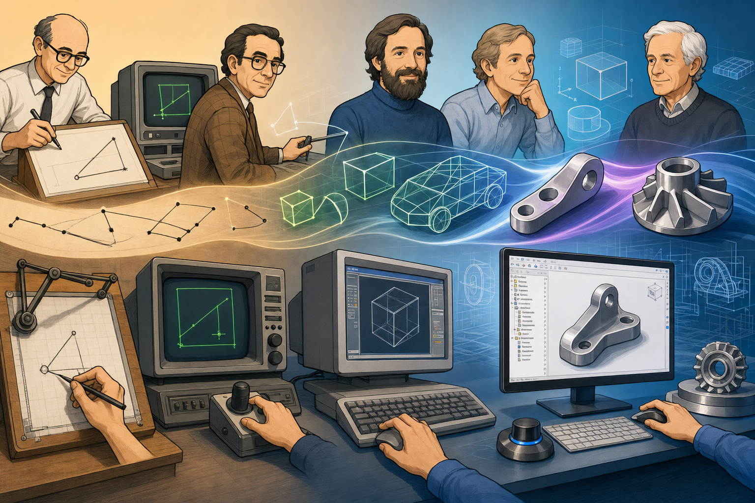


From Sketchpad to CAD: The People Who Made Interactive Design Possible
Interactive design began as a research problem
Modern design software was not created by software companies alone. It emerged from a long chain of work by engineers, mathematicians, computer scientists, manufacturing researchers, aerospace specialists, automotive stylists, and industrial laboratories that were trying to solve problems far harder than computerized drafting. The central challenge was not simply to display a line on a screen, but to make geometry editable, precise, repeatable, constrained, manufacturable, and understandable to both human designers and machines. Before CAD became a commercial category, it was an answer to urgent technical pressure from organizations such as MIT Lincoln Laboratory, General Motors, Lockheed, Boeing, and IBM, where design complexity was beginning to exceed what manual drafting rooms could manage efficiently. Aircraft, missiles, automobiles, machine tools, and electronic systems required thousands of interdependent drawings, and any design change could ripple through an entire engineering organization. The history of CAD therefore begins not with a single product launch, but with the recognition that design itself had to become computational.
Ivan Sutherland and the grammar of interactive graphics
The breakthrough most often cited as the symbolic birth of interactive CAD is Ivan Sutherland’s Sketchpad, created at MIT in 1963 as part of his doctoral work. Sketchpad ran on the TX-2 computer at MIT Lincoln Laboratory and used a light pen to let a designer draw, edit, copy, constrain, and manipulate graphical objects directly on a display. That may sound ordinary today, but in the early 1960s it was radical because computing was still dominated by batch processing, punched cards, and delayed output. Sutherland showed that a computer could be a live design partner rather than a remote calculating machine. Sketchpad introduced ideas that later became normal in CAD, vector illustration systems, graphical user interfaces, and object-oriented design environments. It supported object instances, so a repeated symbol could be edited through a master definition. It supported constraints, allowing lines to remain parallel, perpendicular, equal in length, or connected as the drawing changed. It also introduced graphical editing concepts that anticipated later CAD commands, handles, and dependency relationships. Sketchpad was not only a drawing tool; it was a demonstration that geometry could be represented as structured information, not merely as pixels or marks.
Human-computer interaction and the design workstation
Douglas Engelbart expanded the human side of this revolution. His work at the Stanford Research Institute, especially the 1968 demonstration later called “The Mother of All Demos,” presented the mouse, windows, hypertext, collaborative editing, screen-based interaction, and real-time computer-supported work. Engelbart was not building CAD in the narrow commercial sense, but his ideas supplied the human-computer interaction foundations on which CAD depended. A powerful geometric modeler would be useless if engineers could not navigate, select, edit, communicate, and revise complex information with speed and clarity. CAD needed pointing devices, displays, command structures, interactive feedback, and eventually networked collaboration. Engelbart’s vision made the computer feel less like a calculator and more like an environment for thought. Design software inherited that ambition directly: the screen became a workspace where visual reasoning, numerical control, and communication could meet. The evolution from light pens to mice, tablets, digitizers, space controllers, and multi-touch interfaces continued this same trajectory. The tool was not just the geometry engine; it was the entire conversational loop between designer and machine.
Patrick Hanratty and the commercial DNA of CAD/CAM
If Sutherland demonstrated what interactive design could be, Patrick J. Hanratty helped turn computational design into a commercial and industrial reality. Often called the “father of CAD/CAM,” Hanratty worked on early numerically controlled manufacturing and developed PRONTO, one of the first programming systems for machine tools, while at General Electric in the 1950s. He later founded companies whose technology influenced a remarkable portion of the CAD market, including systems connected historically to platforms such as AutoCAD and MicroStation. Hanratty’s importance lies in connecting geometry to production. For industrial companies, a digital drawing was valuable, but a digital design that could help drive manufacturing was transformative. His work sat at the interface between drafting, toolpath generation, part definition, and factory automation. This was the practical zone in which CAD and CAM became mutually reinforcing disciplines. Aerospace and automotive firms did not merely want images; they wanted reliable geometry that could reduce rework, improve manufacturing coordination, and preserve design intent across departments. In that context, early CAD was less about making drafting convenient and more about making industrial complexity governable.
- Sketchpad established interactive geometry, constraints, object instances, and graphical editing.
- Engelbart’s research established the interaction model that made screen-based design usable.
- Hanratty’s CAD/CAM work connected digital geometry to manufacturing and commercial deployment.
- Aerospace, defense, automotive, and manufacturing organizations supplied the economic pressure that pushed CAD from research into industry.
The Mathematicians Behind Curves, Surfaces, and Solid Modeling
Geometry became powerful when it became mathematical
CAD became genuinely powerful when it learned to describe geometry mathematically rather than only visually. A line drawing could represent an object, but it could not fully encode smoothness, curvature, tangency, manufacturability, or the subtle surface transitions required for cars and aircraft. Automotive and aerospace design forced software developers to confront the fact that industrial form is not made of simple straight edges. Car bodies, turbine blades, fuselages, consumer products, and molded components depend on continuous curves and surfaces that must be aesthetically controlled and physically manufacturable. This required mathematical tools that could describe shapes compactly while still giving designers intuitive control. The great leap was the shift from manually drafted contours to computational curves and surfaces governed by control points, blending conditions, continuity classes, and stable evaluation algorithms. In practice, this meant that an automobile body surface could be adjusted through a mathematical representation, analyzed for smoothness, and transferred to tooling processes with much greater consistency. The designer’s eye remained essential, but the final authority increasingly became a mathematical definition of shape.
Pierre Bézier, Paul de Casteljau, and automotive curve control
Pierre Bézier, working at Renault, became one of the most famous names in digital curve and surface modeling because his work helped automate car body design and manufacturing preparation. Bézier curves allowed complex shapes to be controlled through a set of points that influenced the curve without requiring every point on the curve to be specified directly. This gave designers and engineers a practical way to create smooth, editable forms. At roughly the same historical moment, Paul de Casteljau at Citroën developed related mathematical methods, including what later became known as the de Casteljau algorithm. His method remains central because it provides a numerically stable way to evaluate Bézier curves through recursive linear interpolation. For CAD history, the Renault and Citroën work is especially important because it shows how industrial styling and manufacturing needs drove mathematical innovation. These were not abstract curves invented in isolation; they were responses to the difficulty of defining full-scale automobile surfaces with precision. The fact that Bézier’s name became more public while de Casteljau’s work remained internal for years also reminds us that corporate secrecy shaped the visibility of technical contributors.
Splines, B-splines, and the mathematical discipline of smoothness
Carl de Boor played a major role in establishing the mathematical basis for spline theory, particularly B-splines, which became foundational in CAD and computer graphics. Splines originated conceptually from flexible drafting strips used by shipbuilders and designers, but digital splines required rigorous numerical definitions. B-splines offered important advantages because they provided local control: moving one control point affected only a portion of the curve rather than disturbing the entire shape. This property was extremely valuable in industrial design because complex surfaces often need localized refinement without destroying surrounding regions. B-splines also supported piecewise polynomial construction, continuity control, and stable mathematical evaluation. As CAD systems matured, surface continuity became an increasingly important language of quality. Designers and engineers distinguished between positional continuity, tangency continuity, and curvature continuity, often described as G0, G1, and G2 in geometric modeling. These distinctions mattered because a surface might be connected but visually poor, tangent but not curvature-smooth, or mathematically smooth but difficult to manufacture. The software had to encode these differences precisely so that visual judgment, engineering analysis, and production requirements could converge.
Ken Versprille and the rise of NURBS
Ken Versprille advanced the theory of NURBS, or Non-Uniform Rational B-Splines, through his 1975 doctoral work at Syracuse University. NURBS became one of the central mathematical languages of high-end CAD, industrial design, and computer graphics because they could represent both freeform shapes and exact conic sections such as circles and ellipses. This mattered enormously. Earlier curve systems could create beautiful freeform geometry, but engineering also required exactness for arcs, cylinders, fillets, and machined features. NURBS provided a unified framework by combining control points, weights, knot vectors, polynomial basis functions, and rational representation. Over time, they became essential in software such as Alias, CATIA, Rhino, and other high-end surface modeling tools used in automotive, aerospace, product design, and entertainment production. NURBS also changed how designers thought about form. Instead of drawing a curve as a fixed mark, they managed a mathematical system of influence. Control vertices, weights, knots, spans, and continuity became part of the working vocabulary of advanced digital design. The visual elegance of a surface was inseparable from the invisible structure beneath it.
- Bézier curves made smooth industrial curves controllable through intuitive control structures.
- The de Casteljau algorithm provided a stable computational method for evaluating Bézier geometry.
- B-splines introduced local control and flexible continuity across piecewise curve segments.
- NURBS unified freeform design with exact analytic geometry, making them essential for industrial modeling.
- Surface continuity became a measure of design quality, manufacturability, and visual refinement.
Kernel Builders, Constraint Solvers, and the Architecture of Modern CAD
From electronic drafting to engineering modelers
The next great transition in design software was the movement from drawing systems to true engineering modelers. Early CAD often improved drafting productivity by replacing paper drawings with electronic lines, layers, symbols, and plotted output. That was important, but it did not fully change the nature of design. A true modeler had to understand that an object was not merely a collection of visible edges; it was a bounded, valid, editable three-dimensional entity with faces, edges, vertices, volumes, features, and design intent. This required a deeper computational architecture. The software needed geometry kernels, topological data structures, Boolean operations, constraint solvers, regeneration systems, dependency graphs, and eventually parametric feature histories. The “magic” of modern CAD lies in this invisible machinery. When an engineer changes a hole diameter in a parametric model and downstream fillets update, the screen animation hides a complex negotiation among topology, numerical solving, surface intersection, feature ordering, and geometric validity. The visible model is only the front end of a much larger mathematical contract.
Boundary representation and the theory of valid solids
Ian Braid was a key figure in early solid modeling theory and boundary representation, often called B-Rep. His research contributed to the idea that a solid could be represented by its enclosing boundaries: faces, edges, and vertices connected through a topological structure and linked to underlying geometry such as planes, cylinders, cones, and spline surfaces. Bruce Baumgart also made important contributions to early polyhedral modeling and boundary representations, helping clarify how computer systems could represent three-dimensional objects through connected surface elements. B-Rep became central because it aligned well with engineering reality. Manufactured parts have surfaces, intersections, edges, holes, blends, and boundaries that must be selected, modified, machined, measured, and inspected. However, B-Rep also introduced difficult problems. A model could look plausible on screen while containing gaps, inconsistent normals, self-intersections, non-manifold edges, or invalid topology. CAD systems therefore needed rules for what counted as a legitimate solid. They also needed robust algorithms for intersecting surfaces, trimming faces, sewing boundaries, and maintaining consistency after edits. Much of CAD development has been a battle against geometric ambiguity.
Requicha, Voelcker, CSG, and manufacturing-oriented geometry
Ari Requicha and Herbert Voelcker were crucial academic figures in formalizing solid modeling and geometric reasoning. Their work helped clarify concepts behind valid solids, representation schemes, constructive solid geometry, and the relationship between geometric models and manufacturing processes. Constructive solid geometry, or CSG, represented objects as combinations of primitive volumes such as blocks, cylinders, spheres, cones, and swept forms joined or subtracted through Boolean operations. This approach was powerful because it mirrored many engineering operations: add material, remove material, bore a hole, cut a slot, intersect volumes, and derive a resulting solid. Boolean operations became essential to CAD, but they are deceptively difficult. Subtracting one shape from another requires calculating intersections, dividing faces, creating new edges, removing obsolete topology, and ensuring the result remains a valid closed volume. Requicha and Voelcker’s importance lies in making these issues rigorous rather than ad hoc. They helped establish that CAD models could support reasoning about production, inspection, tolerances, and manufacturability only if the underlying representation had mathematical discipline. A pretty picture was not enough; an engineering model had to be logically valid.
Samuel Geisberg and the parametric feature revolution
Samuel Geisberg, founder of PTC, helped bring parametric, feature-based modeling into mainstream engineering practice through Pro/ENGINEER, released in the late 1980s. This was one of the decisive commercial shifts in CAD history. Instead of treating geometry as a mostly static result, Pro/ENGINEER treated the model as a sequence of features governed by dimensions, constraints, and relationships. A part might begin as an extrusion, followed by cuts, holes, rounds, patterns, shells, drafts, and datum references. If a dimension changed, the system regenerated the feature tree and attempted to preserve the design intent. This approach changed engineering workflows because designers could explore variation, build families of parts, and encode functional relationships directly into the model. Parametric modeling also brought new challenges. Feature trees could become fragile, parent-child dependencies could fail, and poorly planned references could make models difficult to modify. Yet the conceptual leap was enormous. CAD was no longer just a place where geometry was drawn; it became a structured history of decisions. The model contained not only shape, but also a record of how that shape was constructed.
Commercial kernels and the industrial infrastructure of CAD
The rise of commercial geometry kernels turned solid modeling from a specialized internal capability into reusable software infrastructure. Spatial Technology developed the ACIS kernel, which became important across many CAD and engineering applications. Shape Data, associated with the development of what became Parasolid, played an equally important role. Parasolid became central to Unigraphics, later Siemens NX, and many other systems, including SolidWorks. These kernels handled core operations such as B-Rep management, surface and curve evaluation, Boolean operations, blending, offsetting, sectioning, and model interrogation. Their presence allowed CAD companies to build higher-level user experiences without reinventing every geometric operation from scratch. Major companies such as Dassault Systèmes, PTC, Siemens, and Autodesk competed not only through interfaces and workflows, but through the reliability of this hidden infrastructure. Users often judged CAD by visible commands, yet the success or failure of a modeling operation frequently depended on low-level numerical robustness. A fillet that succeeds, a shell that does not collapse, or a Boolean that preserves valid topology reflects decades of kernel engineering.
- B-Rep represents solids through connected faces, edges, vertices, and underlying analytic or spline geometry.
- CSG represents solids through combinations of primitives and Boolean operations.
- Boolean operations are foundational but require difficult intersection and topology-rebuilding algorithms.
- Parametric modeling connects geometry to dimensions, constraints, formulas, and regeneration histories.
- Feature trees preserve design construction logic, but also introduce dependency management challenges.
- Constraint solvers maintain relationships such as tangency, symmetry, equality, coincidence, and perpendicularity.
The Invisible Mathematics Beneath Everyday CAD Commands
Why a simple edit is rarely simple
One reason CAD history is so interesting is that ordinary commands conceal extraordinary computational work. When a designer drags a sketch line, the system may invoke a constraint solver to preserve coincident endpoints, equal lengths, angular relationships, dimensional constraints, and symmetry conditions. When an engineer rounds an edge, the modeler must construct a blend surface, trim neighboring faces, update topology, handle corner conditions, and verify that the resulting body remains valid. When a shell command hollows out a plastic enclosure, the kernel must offset faces, resolve self-intersections, rebuild edges, and deal with small features that may vanish or collide. These operations depend on numerical methods, symbolic relationships, topology graphs, tolerance management, and geometric reasoning. The user experiences them as direct manipulation, but the system experiences them as a sequence of mathematical obligations. This is why two CAD systems can appear similar on the surface yet behave very differently on difficult geometry. Reliability is not only a user-interface achievement; it is the result of extremely deep modeling architecture.
Dependency graphs and design intent
Modern parametric CAD relies heavily on dependency graphs that describe how one element of a model depends on another. A sketch may depend on a datum plane; an extrusion may depend on the sketch; a hole pattern may depend on the extrusion face; a drawing view may depend on the solid model; a manufacturing toolpath may depend on the part geometry. This chain is powerful because it allows changes to propagate, but it also means the software must decide what to recompute, what to preserve, and what to declare failed. Design intent is the phrase often used to describe the expected behavior of a model when it changes, but design intent is not a mystical property. It is encoded through constraints, references, dimensions, feature order, equations, naming schemes, and modeling habits. Software builders have spent decades trying to make these relationships more stable. Direct modeling, synchronous technology, history-based modeling, and hybrid systems all represent different answers to the same problem: how can CAD preserve engineering meaning while allowing geometry to change fluidly? That question remains central even in cloud-based and AI-assisted tools.
- Topology describes how geometric elements are connected, not merely where they appear in space.
- Numerical tolerance determines when points, edges, and surfaces are considered coincident or separate.
- Regeneration recalculates model features in a controlled order after changes are made.
- Design intent is built from constraints, references, feature structure, and engineering assumptions.
Conclusion: Modern Design Software Is a Monument to Hidden Technical Labor
The product names are only part of the story
The history of design software is often told through famous products, but it should also be told through the people who made digital design mathematically possible. Ivan Sutherland made design interactive and showed that geometry could be manipulated directly on a screen as structured information. Douglas Engelbart helped define the interactive computing environment that made visual design work practical. Patrick Hanratty connected digital geometry to manufacturing and helped create the commercial foundations of CAD/CAM. Pierre Bézier, Paul de Casteljau, Carl de Boor, and Ken Versprille gave designers mathematical control over curves and surfaces, enabling the smooth, precise, manufacturable forms required by automotive and aerospace industries. Ian Braid, Bruce Baumgart, Ari Requicha, and Herbert Voelcker helped establish rigorous theories of solids, boundaries, topology, and constructive modeling. Samuel Geisberg and other commercial CAD pioneers transformed these ideas into practical engineering workflows that changed how products are conceived, revised, documented, and manufactured.
The future belongs to hybrid thinkers
Every modern CAD model carries decades of accumulated research in geometry, computation, and engineering practice. A simple parametric part in a contemporary system may contain ideas from Sketchpad, spline mathematics, NURBS theory, B-Rep topology, CSG reasoning, constraint solving, feature history, numerical analysis, and manufacturing automation. Today’s advances in generative design, cloud CAD, simulation-driven design, additive manufacturing preparation, real-time visualization, and AI-assisted modeling are not departures from this tradition; they are extensions of it. Generative design still depends on geometric representation and manufacturable constraints. Cloud CAD still depends on kernels, solvers, and versioned model data. AI-assisted modeling still needs reliable geometry to act upon, otherwise generated suggestions remain superficial. The future of design software will likely belong to the same kind of hybrid thinkers who shaped its past: engineers who understand mathematics, mathematicians who understand design, and software builders who can turn theory into dependable tools. The most important inventions may continue to be invisible to the casual user, hidden inside kernels, solvers, representations, and algorithms, but they will determine what designers are able to imagine, test, and build.
Also in Design News