Your Cart is Empty
Customer Testimonials
-
"Great customer service. The folks at Novedge were super helpful in navigating a somewhat complicated order including software upgrades and serial numbers in various stages of inactivity. They were friendly and helpful throughout the process.."
Ruben Ruckmark
"Quick & very helpful. We have been using Novedge for years and are very happy with their quick service when we need to make a purchase and excellent support resolving any issues."
Will Woodson
"Scott is the best. He reminds me about subscriptions dates, guides me in the correct direction for updates. He always responds promptly to me. He is literally the reason I continue to work with Novedge and will do so in the future."
Edward Mchugh
"Calvin Lok is “the man”. After my purchase of Sketchup 2021, he called me and provided step-by-step instructions to ease me through difficulties I was having with the setup of my new software."
Mike Borzage
Create Stunning 3D Models With BricsCAD 2023 Civil Explorer!
August 18, 2023 2 min read

BricsCAD V23.2 Civil Explorer revolutionizes the way civil engineers and surveyors work by providing powerful tools for creating and editing TIN surfaces. With these features combined, BricsCAD V23.2 Civil Explorer is truly the best CAD software solution for creating stunning 3D models in no time at all!
Creating & Editing TIN Surfaces
BricsCAD's Civil Explorer enables users to create alignments, surfaces, and volume surfaces from drawing objects in DWG format. The software also offers visibility options that can be applied to alignments or profiles. This allows you to specify which entities are visible or hidden when creating surface models.
To create a TIN surface from a DWG file using BricsCAD, simply right-click on the TINsurfaces option in the ribbon menu and select "Create". You will need to select a boundary to clean up the edges. This can be done using a 2D polyline or manually deleting individual lines as required. Additional edge cleanup can be performed in Civil Explorer by accessing its Definitions. This will display all the operations used to create the surface. You can double-click on the "Remove outer edges" command and change the inputted value to meet your project requirements.
Adjusting Visual Styles to Improve Breakline Visibility
Adjusting Visual Styles is key for making sure that breaklines are visible on the screen. To do this, turn off triangles and turn on contours, which will help make those important lines more visible when creating and editing TIN surfaces. Once these settings have been adjusted, breaking lines should appear in yellow on the screen. Double click on the Add Breakline button to review their information if needed!
Additionally, right-clicking allows users to zoom in or select anything from the screen, which is incredibly useful when it comes to editing breaklines. This way, breaklines can stretch around and change the surface accordingly, making it easier than ever before! For large data sets such as point clouds, TIN surfaces can be created using Create from Point Cloud. This feature filters points based on parameters such as radius or elevation, so you don't have any unnecessary clutter cluttering up your viewport! Once filtering is complete, users will receive a quick report back at the command line before being able to create a TIN surface that looks smooth overall but requires zooming in for finer details.
Also in Design News

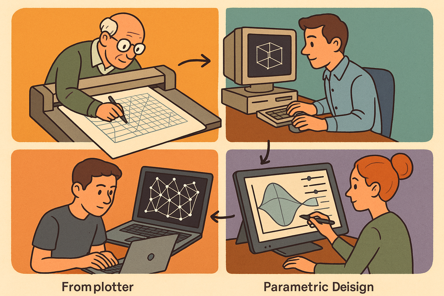
Design Software History: From Plotters to Procedural Intent: A Technical History of Generative and Parametric Design Software
January 04, 2026 13 min read
Read More
Semantic Meshes: Enabling Analytics-Ready Geometry for Digital Twins
January 04, 2026 12 min read
Read MoreSubscribe
Sign up to get the latest on sales, new releases and more …


